
CNC milling is a subtractive manufacturing process that uses rotating cutting tools to remove material from a solid workpiece, producing precise 2D and 3D geometries. Driven by computer numerical control (CNC), milling machines execute programmed toolpaths with high accuracy and repeatability. This article explains CNC milling processes, equipment, materials, parameters, tolerances, surface finishes, and typical industrial applications.
Fundamentals of CNC Milling
CNC milling uses computer-controlled motion along multiple axes to guide a rotating cutter relative to a fixed or moving workpiece. The core principle is controlled material removal to achieve a specified geometry, dimension, and surface quality.
Basic Process Flow
The general workflow of CNC milling includes:
- Part design in CAD software
- Toolpath generation in CAM software
- Post-processing to create CNC code (G-code, M-code)
- Machine setup: workholding, tool loading, zero-point setting
- Dry run or verification
- Production run and inspection
Subtractive Manufacturing Characteristics
CNC milling is inherently subtractive: the final geometry results from continuous chip formation. This enables tight tolerances and good surface finishes, especially for metals and engineering plastics. However, material utilization is lower than near-net-shape processes because excess stock is removed as chips.
CNC Milling Machine Types and Configurations
CNC milling machines differ in axis configuration, spindle orientation, and structural design. These differences strongly affect reachable geometries, achievable accuracy, and productivity.
Vertical vs. Horizontal Milling Machines
Vertical machining centers (VMCs) have a vertically oriented spindle. Workpieces are usually clamped on a horizontal table, often with three linear axes (X, Y, Z). VMCs are common in job shops due to their relatively compact footprint, versatile tooling, and straightforward chip evacuation for many parts.
Horizontal machining centers (HMCs) have a horizontally oriented spindle and typically use rotary pallets or tombstones. Gravity assists chip evacuation, which is advantageous for high-volume production and deep-pocket machining. HMCs are often selected for complex prismatic parts requiring multiple faces to be machined in a single setup.
3-Axis, 4-Axis, and 5-Axis Machines
Axis count describes how many directions of motion can be controlled simultaneously:
- 3-axis: Linear motion in X, Y, Z. Suitable for 2D profiles, pockets, and 3D surfaces with a single tool orientation.
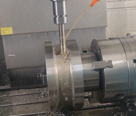
- 4-axis: Adds one rotary axis (A or B), enabling machining of multiple sides by rotating the workpiece. Useful for shafts, impellers with simple blade orientations, and indexing operations.
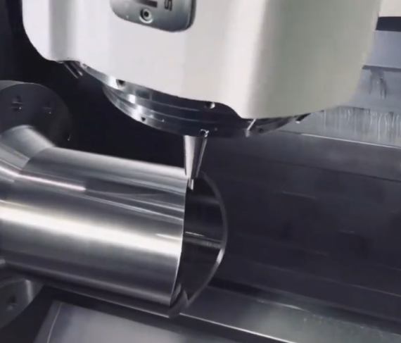
- 5-axis: Adds two rotary axes, allowing tool orientation to be adjusted during cutting. Enables machining of undercuts, complex freeform surfaces, and parts in a near-single setup.
Simultaneous 5-axis milling allows continuous tool orientation control, reducing tool length, improving surface quality, and accessing complex features. Indexed 5-axis machining uses rotary axes for positioning between cuts rather than during cutting.
Key Machine Components
Core elements of a CNC milling machine include:
Spindle: Provides rotational motion and power to the cutting tool. Spindle speed range and power rating determine feasible materials and cutting conditions.
Linear axes and drives: Ball screws or linear motors, combined with linear guides, provide precise positioning. Encoder feedback ensures positional accuracy.
Tool changer: Automatic tool changers (ATCs) store and switch tools during machining. Tool capacity and change time affect productivity.
Control system: CNC controller interprets G-code, manages axis motion, tool compensation, and auxiliary functions (coolant, probing).
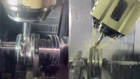
Coolant and chip management: Coolant delivery and chip conveyors maintain cutting performance and machine reliability.
CNC Milling Operations and Toolpath Strategies
Milling comprises different types of cutting operations and toolpath strategies that affect cycle time, tool life, and surface quality.
Common Milling Operations
Milling operations can be classified by how the cutting tool engages the workpiece:
Face milling: The tool axis is perpendicular to the surface. Used to produce flat surfaces and achieve accurate heights. Face mills often have multiple indexable inserts.
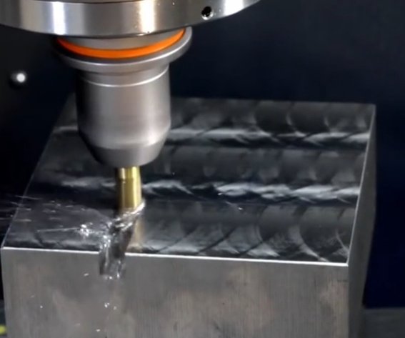
End milling: The tool axis is parallel to the direction of milling. End mills cut on the side and sometimes at the tip, enabling pockets, slots, and contours.
Slotting: Creation of grooves or keyways with specified width and depth using end mills or slotting cutters.
Profile milling: Following 2D or 3D contours, including internal and external profiles.
Pocket milling: Removing material from enclosed areas with defined boundaries, often using roughing and finishing passes.
Drilling, reaming, and tapping on machining centers: Performed using the same CNC platform, though they are technically separate processes.
Climb vs. Conventional Milling
In climb milling (down milling), the cutter rotates in the same direction as the feed. Chip thickness starts at maximum and decreases to zero. This typically results in better surface finish, improved tool life, and reduced cutting forces on modern rigid CNC machines.
In conventional milling (up milling), the cutter rotates against the feed direction. Chip thickness starts at zero and increases to maximum. This can be advantageous for certain setups with backlash concerns, but is less common with modern CNC equipment.
Roughing and Finishing Strategies
Roughing operations prioritize rapid material removal, using higher feed rates, deeper axial depths, and optimized toolpaths. Finishing operations use smaller stepovers and shallower depths to meet tolerance and surface finish requirements.
Adaptive or high-efficiency roughing toolpaths maintain constant cutter engagement, reducing peak cutting forces. Traditional offset or zigzag toolpaths are simpler but may cause variable loads.
Cutting Tools for CNC Milling
Tool selection strongly influences productivity, dimensional accuracy, and surface quality. Choosing appropriate tool geometry and material is essential for a stable process.
Tool Types and Geometries
Common milling cutting tools include:
End mills: Flat-end, ball-nose, and corner-radius end mills used for pockets, slots, and profiling. Ball-nose tools are widely used for 3D surface finishing.
Face mills: Large-diameter tools with multiple inserts for efficient face machining of large surfaces.
Slotting cutters and side-and-face mills: Used for wide slots and deep grooves.
Form mills: Custom profiles for specific geometries such as gear teeth or complex edges.
Key geometrical parameters include flute count, helix angle, corner radius, and overall length. For example, tools for roughing may have higher flute counts and stronger cores, while finishing tools may have sharper edges and optimized relief to minimize vibration.
Tool Materials and Coatings
Typical tool materials include:
High-speed steel (HSS): Tough and relatively inexpensive, used for lower-speed operations and simpler geometries.
Cemented carbide: High hardness and hot hardness, enabling higher cutting speeds. Widely used for production milling in metals.
Cermet, ceramics, and polycrystalline diamond (PCD): Applied for specialized high-speed or abrasive material machining, such as cast irons or aluminum-silicon alloys.
Coatings such as TiN, TiCN, TiAlN, AlTiN, and DLC reduce friction, enhance wear resistance, and improve temperature stability. Correct coating choice depends on workpiece material and cutting conditions.
Workholding and Fixturing in CNC Milling
Workholding is critical for dimensional accuracy and process stability. Poorly designed fixturing can lead to chatter, misalignment, and geometric errors.
Common Workholding Methods
Vices: Flexible clamping for prismatic parts. Soft jaws can be machined to match specific part geometries.
Clamping kits and step blocks: Used directly on the machine table or fixture plates to secure irregular shapes.
Modular fixturing systems: Plates with grid or slot patterns for repeatable setups and reduced changeover time.
Rotary fixtures and indexers: Enable multi-side machining on 4-axis or 5-axis machines.
Vacuum fixtures: Useful for thin plates and large flat parts where mechanical clamps might distort the workpiece.
Fixturing Considerations
Effective fixturing addresses:
Location and orientation: Precise referencing of part datums in X, Y, and Z.
Clamping force: Sufficient to resist cutting forces without deforming the part.
Accessibility: Allowing tool access to all required features while minimizing repositioning.
Repeatability: Consistent positioning for batch production, often with locating pins or dedicated nests.
Materials for CNC Milling
CNC milling is compatible with a wide range of metals and plastics. Material selection affects tool wear, achievable tolerances, cutting forces, and surface finish.
Metals
Common metallic materials include:
Aluminum alloys (e.g., 6061, 6082, 7075): Good machinability, relatively low cutting forces, and suitable for components requiring a balance of strength and low weight.
Carbon steels (e.g., 1018, 1045): Used for structural parts, shafts, and general-purpose components. Machinability varies with carbon content and heat treatment condition.
Alloy steels (e.g., 4140, 4340): Provide higher strength and toughness. Often machined in pre-hardened or quenched-and-tempered states.
Stainless steels (e.g., 304, 316, 17-4PH): Corrosion-resistant alloys, typically more demanding to machine due to work hardening and lower thermal conductivity.
Copper and copper alloys (e.g., brass, bronze): Good thermal and electrical conductivity, but can be sticky or prone to burr formation.
Titanium alloys (e.g., Ti-6Al-4V): High strength-to-weight ratio and good corrosion resistance. Require optimized parameters to manage heat and tool wear.
Plastics and Composites
Engineering plastics are frequently milled for prototypes, test fixtures, and functional components. These include:
ABS and polycarbonate: Used for housings, enclosures, and test parts.
Acetal (POM): Good dimensional stability and low friction, suitable for gears and sliding components.
Nylon, PEEK, and other high-performance polymers: Used in demanding mechanical or thermal environments.
Fiber-reinforced composites require suitable tools and dust extraction, as fibers can accelerate tool wear and fine dust requires controlled handling.
Cutting Parameters in CNC Milling
Cutting parameters determine chip load, heat generation, and tool life. Proper parameter selection is essential for stable and economical machining.
Key Cutting Parameters
The main parameters include:
Spindle speed (n): Rotational speed of the tool in revolutions per minute (rpm).
Cutting speed (Vc): Surface speed at the tool periphery, typically expressed in m/min or ft/min.
Feed per tooth (fz): Linear distance the tool advances for each tooth per revolution.
Feed rate (vf): Linear velocity of the tool relative to the workpiece, often in mm/min or in/min.
Axial depth of cut (ap): Depth of tool engagement along the tool axis.
Radial depth of cut (ae): Width of tool engagement in the radial direction.
| Workpiece Material | Tool Material | Typical Cutting Speed Range (Vc) |
|---|---|---|
| Aluminum alloys | Carbide | 150–600 m/min |
| Low carbon steel | Carbide | 80–250 m/min |
| Alloy steel (pre-hardened) | Carbide | 60–180 m/min |
| Stainless steel | Carbide | 60–180 m/min |
| Titanium alloys | Carbide | 30–120 m/min |
| Engineering plastics | Carbide | 100–400 m/min |
Parameter Relationships
The relationships between parameters are fundamental for programming:
Cutting speed and spindle speed: Spindle speed is derived from cutting speed and tool diameter:
n = (1000 × Vc) / (π × D) (for metric units, Vc in m/min, D in mm, n in rpm)
Feed rate from feed per tooth:
vf = n × z × fz
where z is the number of teeth (flutes) on the tool.
For roughing, higher axial and radial depths of cut and moderate feeds are common, while finishing uses lower depths and finer feeds to achieve dimensional and surface quality targets.
Accuracy, Tolerances, and Surface Finish
CNC milling is widely used when dimensional precision and controlled surface finish are required. Achievable tolerances depend on machine capability, tooling, fixturing, and process setup.
Tolerances in CNC Milled Parts
Standard commercial CNC milling processes can often achieve tolerances on the order of ±0.05 mm for typical features, assuming proper setup and stable conditions. With carefully controlled processes, high-quality machines, and suitable environmental control, tolerances of ±0.01 mm or finer may be achievable for specific features.
Factors influencing tolerance include:
Machine geometric accuracy, thermal stability, and backlash compensation.
Tool deflection and wear, affected by tool length, cutting forces, and material.
Fixturing rigidity and clamping strategy.
Measurement methods and referencing strategy for inspection.
Surface Finish Considerations
Surface finish is typically quantified using roughness parameters such as Ra (arithmetical mean roughness). CNC milling can produce a wide range of surface finishes depending on tool geometry, path strategy, and cutting conditions.
| Operation Type | Typical Ra Range | Notes |
|---|---|---|
| Rough milling | 3.2–12.5 μm | High material removal, visible tool marks |
| Standard finish milling | 1.6–3.2 μm | General-purpose finished surfaces |
| Fine finish / semi-finishing | 0.4–1.6 μm | Reduced step-over and optimized parameters |
| High-quality finishing | 0.2–0.4 μm | Dedicated finishing tools and fine feeds |
Improving surface finish typically involves using sharp tools, appropriate tool coatings, stable fixturing, optimized spindle speed and feed, and reduced radial step-over in finishing passes.
Programming and CAM for CNC Milling
Milling operations are executed via CNC programs generated from CAM software or manually coded. CAM systems translate 3D models into optimized toolpaths and process parameters.
G-Code and CNC Control
G-code is the predominant language used to control CNC machines. G-commands specify motion types (linear moves, circular interpolation), coordinate systems, canned cycles, and other operations. M-codes handle auxiliary functions such as spindle on/off, coolant control, and tool change commands.
Typical programming inputs include tool length and diameter offsets, work coordinate systems (e.g., G54–G59), feed rates, spindle speeds, and dwell times. Tool compensation modes allow the control to adjust for cutter radius and length in real time.
CAM Workflow
The CAM programming process usually consists of:
Importing CAD models (solid or surface geometry).
Selecting machining strategies for each feature (pockets, holes, profiles, 3D surfaces).
Assigning tools and cutting parameters for roughing and finishing.
Defining stock geometry and workholding elements where necessary.
Simulating toolpaths to detect collisions, over-travel, and remaining stock.
Post-processing the confirmed toolpaths into controller-specific G-code.
Accurate definition of stock, fixtures, and machine limits in CAM reduces the risk of crashes and ensures that the simulated process reflects the real machining environment.
Quality Control and Inspection of Milled Parts
Inspection verifies that milled parts meet dimensional, geometric, and surface requirements. Appropriate quality control maintains consistency and reduces scrap.
Inspection Methods
Common inspection techniques for CNC-milled parts include:
Hand tools: Calipers, micrometers, height gauges for simple dimensional checks.
Coordinate measuring machines (CMMs): Provide precise 3D measurements of complex geometries and GD&T features such as position, flatness, and perpendicularity.
Optical and vision systems: Suitable for small features, micro-components, and non-contact measurement.
Surface roughness testers: Stylus profilometers or optical systems used to measure Ra and other surface parameters.
Process Control Considerations
Effective process control may involve:
In-process probing to locate workpiece origins, compensate for misalignment, and adjust for tool wear.
Statistical process control (SPC) to monitor key dimensions and maintain process capability within defined limits.
Tool life tracking and scheduled tool changes to avoid unexpected failure during critical finishing operations.
Typical Issues in CNC Milling Projects
Several recurring issues can affect CNC milling projects if not addressed during design and planning.
Feature Accessibility and Tool Reach
Deep pockets, narrow channels, and internal corners can be difficult to reach with standard tools. Long tools required for deep features are more prone to deflection and vibration, potentially leading to dimensional deviation and poor surface finish. Early consideration of minimum corner radii, pocket depth-to-width ratios, and tool access directions reduces these issues.
Part Distortion and Clamping Deformation
Thin walls, slender ribs, and large flat areas can deform due to clamping forces or residual stresses released during machining. Insufficiently rigid fixturing or aggressive cutting parameters increase the likelihood of distortion. Strategies such as balanced material removal, optimized clamping, and stress-relief operations help mitigate these problems.
Applications of CNC Milling
CNC milling is employed across many industries for both prototypes and production components. Its accuracy and flexibility make it suitable for a broad spectrum of applications.
Aerospace and Defense
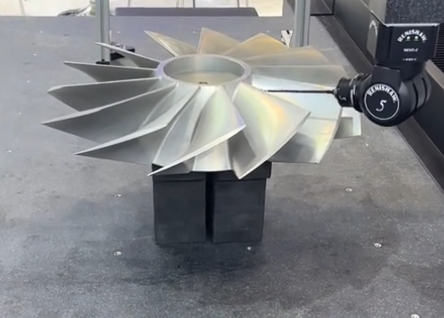
In aerospace, CNC milling is used to produce structural components, brackets, housings, and complex 5-axis parts such as impellers and turbine components. Lightweight alloys like aluminum and titanium are commonly milled to tight tolerances and stringent surface requirements.
Automotive and Transportation
Automotive applications include engine components, transmission housings, fixtures, and tooling. Housings with multiple mounting faces, channels, and sealing surfaces benefit from multi-axis milling to reduce setups and ensure feature alignment.
Medical and Dental Devices
Medical applications involve surgical instruments, orthopedic implants, dental abutments, and prosthetic components. These parts often require biocompatible materials such as stainless steel, titanium, and cobalt-chrome alloys, combined with precise geometries and fine surface finishes.
Industrial Equipment, Tooling, and Molds
CNC milling is widely used for mold and die manufacture, including injection molds, die-casting molds, and stamping dies. Freeform surfaces in mold cavities are typically created with 3-axis and 5-axis finishing strategies using ball-nose and taper-end mills. In addition, fixtures, jigs, and machine components for industrial equipment are frequently produced by milling.
Electronics, Consumer Products, and Prototyping
Electronics housings, heat sinks, and mechanical components for consumer devices are often milled from aluminum or engineering plastics. CNC milling is also a preferred method for rapid prototyping, allowing functional parts to be produced directly from CAD models with short lead times and without the need for specialized tooling.
Design Considerations for CNC-Milled Parts
Designing with CNC milling in mind improves manufacturability, cost-efficiency, and consistency.
Geometrical Design Guidelines
Typical design considerations include:
Minimum internal radii: Milling tools have finite diameters; internal corners require corner radii equal to or greater than the cutter radius. Sharp internal corners generally require secondary processes.
Feature dimensions vs. tool size: Very narrow slots or small holes may require micro-tools with reduced rigidity, affecting achievable tolerances and cost.
Depth-to-width ratios: Deep, narrow pockets are more difficult to machine and can cause tool deflection. Limiting depth relative to tool diameter improves stability.
Wall thickness: Excessively thin walls are prone to vibration and deformation. Specifying practical wall thicknesses supports better process stability.
Datum and Tolerancing Strategy
Clear datum structures and realistic tolerances are essential. Overly tight tolerances increase inspection effort and machining time. A logical datum scheme that reflects functional relationships among features allows efficient fixturing and measurement, while geometric dimensioning and tolerancing (GD&T) helps communicate form, orientation, and position requirements.
