
CNC (Computer Numerical Control) manufacturing is a systematic process that converts digital models into precise physical parts using automated machine tools. This guide explains the complete workflow from initial concept to finished part, covering technical details that matter in professional production environments.
About the CNC Manufacturing Workflow
CNC manufacturing follows a repeatable, step-by-step workflow. Each phase must be understood and controlled to achieve accurate, cost-effective, and consistent components.
The typical start-to-finish workflow includes:
- Product definition and design
- Material selection
- Design for manufacturability (DFM) review
- CAD modeling
- CAM programming and toolpath generation
- Process planning and documentation
- Machine setup and fixturing
- Cutting parameter definition
- Trial runs and first-article inspection
- Production machining
- Post-processing and finishing
- Final inspection and delivery
Product Definition and Requirements
The process begins with a clearly defined product requirement. This step frames all subsequent decisions.
Functional Requirements
The designer must specify:
- Primary function of the part (load-bearing, sealing, alignment, aesthetics, etc.)
- Operating conditions (temperature, environment, exposure to chemicals or moisture)
- Mechanical loads (tension, compression, bending, torsion, impact)
- Interface requirements (mating parts, fasteners, assembly sequence)
Dimensional and Tolerance Requirements
Dimensional accuracy drives machining complexity and cost. Key aspects include:
Linear dimensions and tolerances: Typical CNC processes routinely achieve ±0.05 mm, with high-precision setups reaching ±0.005 mm depending on machine capability and process control.
Geometric tolerances (GD&T) commonly used in CNC manufacturing:
| GD&T Symbol | Control Type | Typical Application | Common Tolerance Range |
|---|---|---|---|
| ⌀ / Position | Feature location | Holes, pins, bosses | 0.01–0.2 mm positional tolerance |
| ⟂ Perpendicularity | Angular control | Mating faces, bores, shafts | 0.01–0.1 mm relative to datum |
| ∥ Parallelism | Angular control | Guides, rails, sliding surfaces | 0.01–0.1 mm across length |
| ⌔ Flatness | Form control | Sealing surfaces, mounting faces | 0.005–0.05 mm per surface |
| ⌭ Cylindricity | Form control | Shafts, precision bores | 0.005–0.05 mm radial |
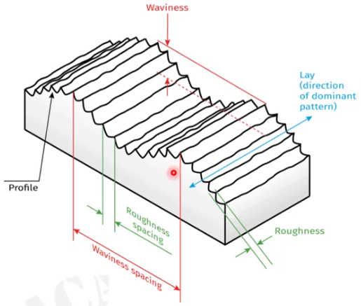
Surface Requirements
Surface finish requirements influence cutting parameters, tool selection, and potential secondary operations.
Typical surface roughness ranges in CNC machining:
| Process | Typical Ra Range (µm) | Use Case | Notes |
|---|---|---|---|
| Rough milling/turning | 3.2–12.5 | Pre-machining, stock removal | Not suitable for sealing or sliding |
| Finish milling/turning | 0.8–3.2 | General-purpose parts | Common for structural components |
| Fine turning/boring | 0.4–1.6 | Bearing seats, fits | Provides reliable alignment |
| Grinding | 0.1–0.4 | Precision fits, sealing faces | Used where tight tolerances and low Ra required |
Material Selection for CNC Manufacturing
Material choice affects machinability, achievable tolerances, tool life, and part performance.
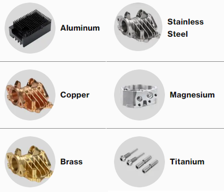
Metals Commonly Used
Typical metals in CNC manufacturing include:
Aluminum alloys (e.g., 6061, 7075, 6082): Good machinability, low density, widely used for housings, brackets, and structural components. Thermal expansion should be considered for tight tolerances.
Carbon steels (e.g., 1018, 1045): Good strength and cost balance. Machinability depends on hardness and composition.
Alloy steels (e.g., 4140, 4340): Used where high strength or toughness is needed. Heat treatment affects hardness and final machining strategy.
Stainless steels (e.g., 304, 316, 17-4PH): Corrosion resistance is the main driver; machinability varies. Austenitic grades (304/316) work harden and may require adjusted feeds and speeds.
Copper alloys (e.g., brass, bronze): Good machinability in many grades, used for fittings, bushings, and components requiring electrical or thermal conductivity.
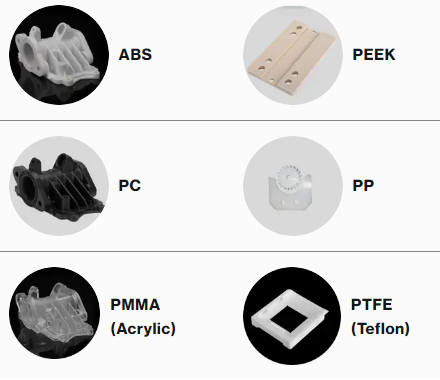
Plastics and Composites
Engineering plastics commonly machined by CNC include POM (acetal), nylon, PTFE, PEEK, and UHMW-PE. Each material has different characteristics in terms of thermal expansion, rigidity, and chip formation.
Key considerations:
Thermal expansion: Plastics expand and contract more than metals. Tolerances must account for operating temperature range.
Clamping and deformation: Soft materials may deform under clamping forces. Fixturing and tool pressure must be managed carefully.
Machinability Factors
When selecting a material for CNC manufacturing, machinability impacts productivity and cost. Factors include:
Hardness and strength: Higher hardness often increases tool wear and may require lower cutting speeds and more rigid setups.
Chip formation: Long, stringy chips can interfere with surface finish and safety; chip-breaking geometries or adjusted cutting parameters are often required.
Thermal properties: Low thermal conductivity materials concentrate heat at the tool-workpiece interface, affecting tool life and dimensional stability.
Design for CNC Manufacturability (DFM)
Design for manufacturability ensures the part can be machined reliably and economically while meeting functional requirements.
Geometry Considerations
Key geometric aspects in CNC design:
Minimum wall thickness: Walls that are too thin are prone to vibration and deformation. For metals, a practical minimum is often around 0.5–1.0 mm depending on size and support; for plastics, thicker walls are usually preferred.
Internal radii: Sharp internal corners cannot be milled with round tools. Corner radii should match or slightly exceed tool radius. For example, using a 6 mm end mill yields a natural corner radius slightly above 3 mm.
Depth-to-diameter ratios: Deep pockets or holes are more challenging. For milling, pocket depth greater than 3–4 times tool diameter may require special strategies; for drilling, depth beyond 5–7 times drill diameter typically needs peck drilling.
Tolerances and Process Capability
CNC processes are capable of high accuracy, but unnecessarily tight tolerances increase cost. A typical approach is:
Use standard tolerances (e.g., ±0.1 mm) for non-critical features.
Reserve tight tolerances (e.g., ±0.01–0.02 mm) for functional fits and alignment-critical features.
Ensure that the specified tolerances align with machine capability, material behavior, and inspection methods.
Fixturing and Accessibility
Features should be designed with machining access and fixturing in mind:
Tool access: Tools must reach all surfaces to be machined. Deep recesses or undercuts may require multi-axis machining or special tooling.
Fixturing surfaces: Provide sufficient flat surfaces or reference planes for clamping and locating. Avoid designs that require complex or unstable clamping for standard operations.

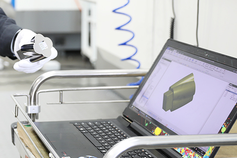
CAD Modeling for CNC Manufacturing
CAD (Computer-Aided Design) is used to create the 3D model that becomes the basis for CNC programming.
Model Requirements
A CNC-ready CAD model should be:
Fully defined: All features, dimensions, and functional surfaces included. Avoid ambiguous or incomplete geometry.
Single solid body (for a single part): Assemblies are broken down into individual parts for machining.
Clean geometry: No gaps, self-intersections, or overlapping entities that can interfere with CAM processing.
File Formats
Common formats accepted by CAM systems include STEP (.step, .stp), IGES (.iges, .igs), and native CAD formats such as .sldprt, .prt, or .xt. STEP is widely used because it preserves solid geometry with broad compatibility.
Dimensioning and Drawing
Although machining can be driven from 3D models alone, technical drawings remain important for:
Defining tolerances, surface finishes, and GD&T.
Communicating critical features and datums to machinists and inspectors.
Documenting inspection requirements and acceptance criteria.
CAM Programming and Toolpath Generation
CAM (Computer-Aided Manufacturing) software translates CAD geometry into machine-readable instructions, generating toolpaths that define how the cutting tool moves.
Toolpath Types
Common toolpath strategies include:
Facing: Planar passes to create flat reference surfaces.
Contour or profile milling: Following part outlines to define external or internal profiles.
Pocketing: Removing material from internal cavities, often using spiral or trochoidal patterns for efficiency.
Drilling and hole-making: Standard drilling, peck drilling, tapping, reaming, and boring operations.
Parallel and 3D finishing: Used for complex surfaces, applying fine stepovers to achieve desired surface finish.
Post-Processing and G-Code
After toolpaths are defined, the CAM system uses a post-processor to convert them into machine-specific code (e.g., G-code for most CNC machines).
Typical elements of CNC code include:
G00 for rapid positioning and G01 for linear cutting moves.
G02/G03 for circular interpolation (clockwise and counterclockwise arcs).
M03/M04 for spindle on (clockwise/counterclockwise) and M05 for spindle stop.
M06 for tool changes.
Feed (F) and spindle speed (S) commands.
Verification and Simulation
Before sending a program to the machine, simulation is used to:
Check for collisions between tool, holder, workpiece, and fixtures.
Confirm stock removal and verify that all features are machined.
Estimate cycle time for planning and cost calculation.

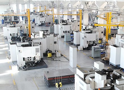
Machine Selection and Process Planning
Selecting the appropriate CNC machine and planning the process sequence are critical for efficiency and quality.
Machine Types
Common machine configurations in CNC manufacturing:
3-axis vertical machining centers (VMC): Suitable for prismatic parts where most features are accessible from one or more vertical setups.
4-axis and 5-axis machining centers: Used for parts requiring multiple orientations or complex surfaces, reducing setups and improving accuracy between features.
CNC lathes (2-axis or multi-axis): Ideal for rotationally symmetric parts. Live tooling and Y-axis capabilities allow milling operations in a single setup.
Process Sequencing
A typical machining sequence includes:
Roughing: Aggressive material removal to approach final shape, leaving a defined allowance for finishing.
Semi-finishing (if needed): Intermediate passes to stabilize geometry and improve conditions for finishing.
Finishing: Light cuts to achieve final dimensions and surface finish.
Drilling and hole finishing: Can be interleaved with roughing/finishing depending on rigidity and accuracy needs.
Tool Selection
Tool choice depends on material, geometry, and surface requirements:
End mills (flat, ball, and corner radius) for milling operations.
Insert-based tools for turning and heavy milling, providing adjustable cutting edges and optimized chip control.
Drills, taps, and reamers for hole-making and threaded features.
Tool material (carbide, high-speed steel, coated carbide) and geometry are chosen based on workpiece material and required cutting conditions.
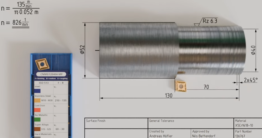
Cutting Parameters and Manufacturing Data
Cutting parameters define how the tool interacts with the workpiece. They directly affect surface finish, tool life, and cycle time.
Core Parameters
Main parameters used in CNC manufacturing include:
Spindle speed (n): Rotational speed of the tool or workpiece, measured in revolutions per minute (rpm).
Cutting speed (Vc): Surface speed at the cutting edge, typically in m/min or ft/min. For milling, Vc = π × D × n, where D is tool diameter.
Feed per tooth (fz): Advance per tooth per revolution, in mm/tooth. For milling, table feed F = fz × z × n, where z is number of teeth.
Feed rate (F): Linear speed of the tool relative to the workpiece, mm/min or in/min.
Depth of cut (ap): Radial or axial engagement of the tool in the material, depending on operation.
Width of cut (ae): Engagement width in milling, influencing load distribution and chip thickness.
Material-Specific Ranges
Approximate cutting speed ranges for carbide tools in milling (example values, actual data depends on tool manufacturer and conditions):
Aluminum alloys: 200–600 m/min with relatively high feed per tooth, due to good machinability.
Carbon steels: 120–250 m/min, adjusting downwards for harder grades.
Stainless steels: 80–180 m/min, with careful heat management and chip control.
Plastics: 150–400 m/min, while controlling heat to avoid melting or surface damage.
Parameter Optimization
Effective parameter selection aims to:
Maintain stable cutting forces to avoid chatter and vibration.
Protect tool life by keeping temperatures and loads within recommended limits.
Achieve the required surface finish in finishing passes with smaller depths of cut and reduced feed.
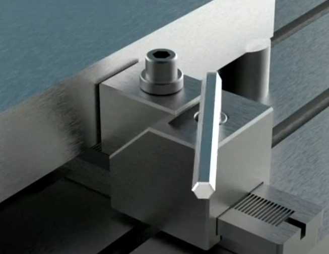
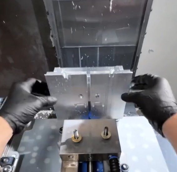
Workholding, Fixturing, and Setup
Secure and precise clamping is a foundational requirement in CNC manufacturing. Poor fixturing leads to dimensional errors, vibration, and potential damage.
Workholding Methods
Common methods include:
Vises: Flexible and suitable for many prismatic parts. Soft jaws can be tailored to part geometry.
Dedicated fixtures: Custom fixtures for higher-volume parts or complex geometries, ensuring repeatability.
Chucks and collets: Used on lathes and sometimes on mills for round parts and bar stock.
Modular fixturing systems: Allow configuring standardized elements to support various parts with minimal setup time.
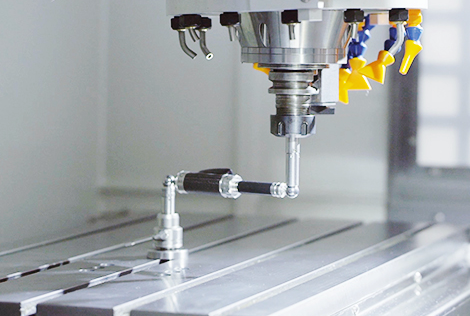
Datum and Zero Point Setting
Machine zero (machine coordinate system) is fixed by the machine design. Work coordinate systems (e.g., G54, G55) establish a part-specific origin.
Key points:
Select consistent and logical datums aligned with drawing references.
Use edge finders, touch probes, or preset fixtures to accurately locate the workpiece.
Document the zero point strategy in setup sheets for repeatable production.
Setup Documentation
Comprehensive setup documentation supports reliability and reproducibility:
Tool list with identifiers, lengths, and diameters.
Workholding description and photos or diagrams.
Work offsets, alignment procedure, and reference surfaces.
Specific notes about orientation, clamping sequence, and any special precautions.
Trial Runs and First-Article Inspection
Before full production, a trial run and first-article inspection validate the process.
Dry Run and Single-Part Test
Initial validation steps often include:
Dry run with the machine running the program above the part or with no workpiece, confirming tool changes and movements.
Single-part machining with conservative parameters to verify toolpaths and fixturing.
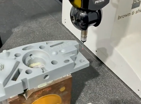
First-Article Inspection (FAI)
FAI compares the first fully machined part against the drawing or specification. It typically includes:
Dimensional checks using calipers, micrometers, bore gauges, height gauges, or coordinate measuring machines (CMM).
Verification of surface finishes where specified.
Confirmation of material specification and any heat treatment or certification requirements.
Production Manufacturing and Process Control
Once the process is validated, production machining can proceed with monitoring and control to maintain quality and efficiency.
Batch Production and Repeatability
In batch manufacturing, consistency is obtained by:
Using standardized setup procedures and documented parameters.
Employing tool presetters and measuring tool lengths and diameters accurately.
Monitoring tool wear and replacing tools based on time, part count, or measured condition.
Process Monitoring
Typical process monitoring practices include:
Periodic in-process measurements of critical features.
Checking for tool wear or chipping, especially for finishing tools.
Observing chip formation and sound for indications of unstable cutting.
Post-Processing and Surface Finishing
After machining, parts may require additional operations to meet functional or aesthetic requirements.
Mechanical Operations
Common mechanical post-processing includes:
Deburring: Removing sharp edges and burrs manually or using tumbling, brushing, or specialized deburring tools.
Grinding: Achieving tighter dimensional tolerances and finer surface finish on specific surfaces.
Polishing or lapping: Used for precise sealing surfaces or optical-quality finishes.
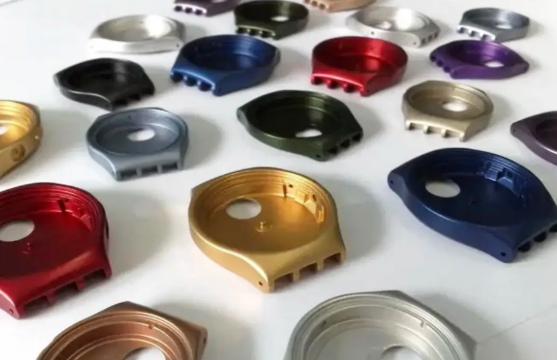
Surface Treatments
Depending on material and application, treatments may include:
Anodizing for aluminum to improve corrosion resistance and surface hardness.
Plating (e.g., zinc, nickel, chrome) for corrosion protection or appearance.
Passivation for stainless steels to enhance corrosion resistance.
Coatings such as powder coating or painting for visual and protective purposes.
Dimensional Inspection and Quality Assurance
Inspection ensures that manufactured parts conform to the specified requirements and that the process remains under control.
Measurement Methods
Measurement tools include:
Hand tools: Calipers, micrometers, thread gauges for routine checks.
Fixed gauges: Plug gauges, ring gauges, and go/no-go gauges for high-volume checking of standard features.
CMMs: Coordinate measuring machines used for complex geometries and tight tolerances, providing detailed reports.
Inspection Planning
A structured inspection plan defines:
Features to be measured and their frequency (100% inspection vs sampling).
Measurement methods and instruments for each feature.
Acceptance criteria, including allowable deviations and rework thresholds.
Documentation and Traceability
Quality documentation typically includes:
Inspection reports with measured values and pass/fail results.
Material certificates and heat treatment records where applicable.
Process records, including machine used, program revision, and operator identification when needed for traceability.
Common Practical Considerations and Issues
CNC manufacturing requires attention to several recurring practical issues that can impact quality, cost, and lead time.
Thermal Effects and Dimensional Stability
Heat generation during machining changes part dimensions temporarily. Considerations include:
Allowing parts to reach ambient temperature before final inspection of critical features.
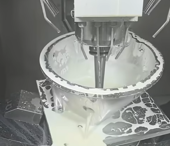
Using coolants or cutting fluids appropriate for the material to control temperature.
Accounting for thermal expansion of both the material and the machine structure in high-precision work.
Tool Wear and Replacement Strategy
Tool wear affects surface finish and tolerances. An effective strategy defines:
Expected tool life based on cutting parameters and material.
Measurement intervals for checking tool conditions.
Predefined replacement criteria (e.g., flank wear limit, number of parts, or cycle time).
Chip Management
Chips must be evacuated efficiently to prevent recutting, surface damage, or machine downtime. Measures include:
Optimized coolant flow direction and volume.
Chip conveyors or augers for automatic chip removal in production environments.
Tool geometry designed for controlled chip breaking.
From Prototype to Production
The CNC manufacturing workflow adapts to both prototype and series production, but emphasis may differ.
Prototype Machining
For prototypes:
Flexibility is prioritized; setups and programs may be adjusted frequently.
Standard tooling and modular fixtures are used to minimize preparation time.
Documentation focuses on capturing effective settings for future runs.
Production Scaling
For production batches:
Stable, repeatable setups are essential.
Cycle time becomes a key metric, influencing toolpaths, cutting parameters, and machine selection.
Process control plans and inspection sampling strategies are formalized.
Integrating CNC Manufacturing into the Supply Chain
In many organizations, CNC machining is one element in a broader manufacturing workflow.
Upstream and Downstream Interfaces
Upstream processes:
Material procurement, including bar, plate, or cast preforms.
CAD design and engineering change management.
Downstream processes:
Assembly, where dimensional compatibility with other parts is critical.
Testing, where machined parts are validated in functional contexts.
Documentation and Communication
Effective communication between design, manufacturing, and quality roles ensures that the CNC process delivers parts that meet functional requirements, deadlines, and cost targets. Clear technical drawings, process sheets, and inspection records support this alignment.
FAQ About CNC Manufacturing
What is CNC manufacturing?
CNC manufacturing means transforming a digital design into a fully machined, finished, and inspected part through a complete, step-by-step production workflow.
What materials can be used in CNC manufacturing?
Common materials include aluminum, steel, titanium, brass, copper, plastics, and composites.
How long does the CNC manufacturing process take?
Lead time depends on design complexity, machining difficulty, finishing requirements, and order quantity—ranging from hours to weeks.
Do I need a 3D model to start CNC manufacturing?
Yes, most CNC manufacturing starts with a CAD model, although many manufacturers can help create or adjust the design.
How can I find a reliable CNC manufacturing supplier?
You can find reliable CNC manufacturers by checking their certifications (such as ISO 9001), reviewing customer feedback, verifying their machining capabilities, requesting sample parts, and comparing lead times, pricing, and communication quality.
