
CNC machining is a subtractive manufacturing process where computer-controlled tools remove material from a solid workpiece to create precise components. It is widely used for prototypes, tooling and full-scale production across automotive, aerospace, medical, consumer products and industrial equipment.
This guide provides a systematic overview of CNC machining types, key machine configurations, common materials, dimensional capabilities, surface finishes and cost structures to support engineering and sourcing decisions.
Calculate Your CNC Machining Cost
CNC Machining Cost CalculatorThis is a simplified estimation tool for reference only. Actual costs depend on part complexity, supplier location, and other factors.
• Prioritize Aluminum 6061 (most common, easy to machine, lower price).
• For small batches(e.g., "free prototyping" or low MOQ).
• Larger quantities dramatically reduce per-part cost by amortizing setup.
• Stick to 3-axis machines—avoid 5-axis (2-3x higher hourly rate).
• Minimize setup time and optimize design (avoid deep pockets, thin walls).
• Use standard stock materials to reduce allowance waste.
What CNC Machining Is and How It Works
CNC (Computer Numerical Control) machining refers to manufacturing processes in which pre-programmed computer software controls the movement of machine tools. The part geometry is defined using CAD (Computer-Aided Design) and converted into toolpaths with CAM (Computer-Aided Manufacturing). The resulting code (often G-code) instructs the machine on tool motion, spindle speeds, feeds and other parameters.
Typical workflow:
- Part design in CAD with specified tolerances and surface requirements
- CAM programming to select tools, strategies and cutting parameters
- Post-processing to generate machine-specific G-code
- Machine setup: workholding, tool loading, work coordinate setting
- Dry run and machining of the part, followed by inspection and finishing
Compared to manual machining, CNC machining offers higher accuracy, repeatability, efficiency and better process control, especially for complex 3D geometries and series production.
Main Types of CNC Machining Processes
CNC machining encompasses multiple processes, each suited to different geometries, tolerances and production volumes. Understanding their specific capabilities helps in proper process selection.
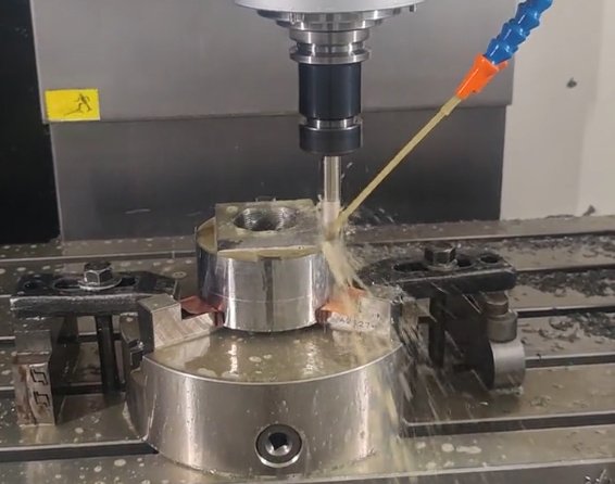
CNC Milling
CNC milling uses rotating cutting tools to remove material from a stationary or moving workpiece. It is extremely versatile and supports prismatic, contoured and freeform surfaces.
Key features:
- Three or more linear axes (X, Y, Z), often with rotary axes for more complex parts
- Suitable for pockets, slots, holes, 3D surfaces, planar faces and complex contours
- Common for housings, brackets, molds, dies, jigs and fixtures
Typical operations include face milling, peripheral milling, pocketing, contouring, drilling, tapping and boring.
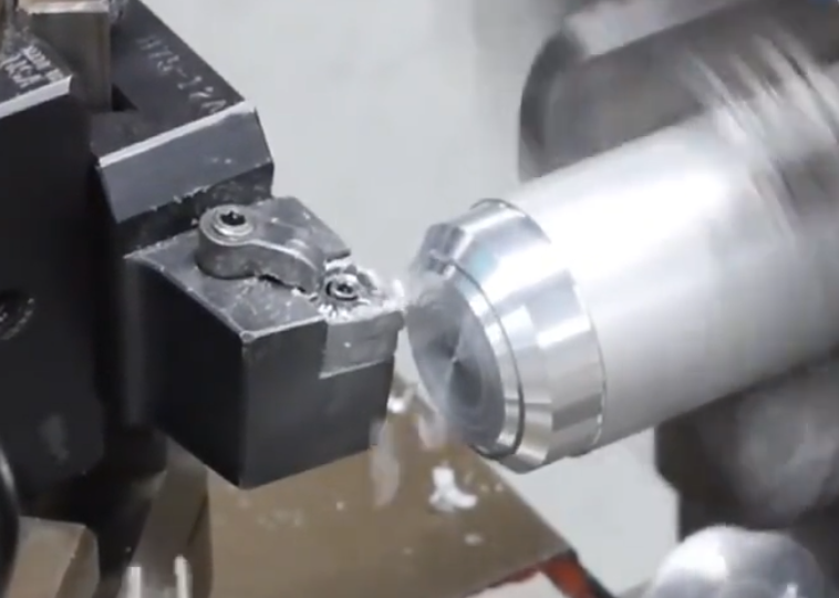
CNC Turning (Lathe Machining)
CNC turning removes material from a rotating workpiece using stationary or moving cutting tools. It is the primary process for axisymmetric components.
Characteristics:
- Workpiece rotates around a single main spindle axis
- Ideal for shafts, bushings, pins, rings, flanges and threaded components
- Operations include rough turning, finishing, grooving, threading, boring and parting-off
Many modern CNC lathes include live tooling and Y-axis capability, enabling milling and drilling features in a single setup, reducing handling and improving positional accuracy.
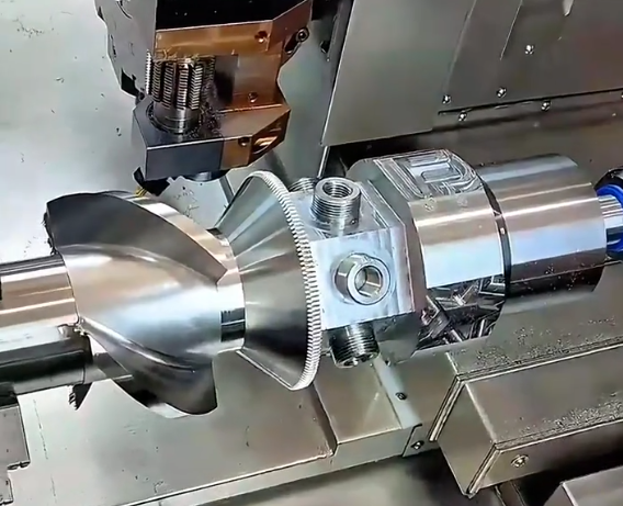
Mill-Turn and Multi-Tasking Machines
Mill-turn machines combine turning centers with full milling capabilities. These multi-tasking machines can perform turning, milling, drilling and tapping in multiple orientations without reclamping the part.
Benefits include reduced setup time, fewer fixtures, improved concentricity and better control of multi-feature relationships (e.g., holes relative to turned diameters). They are well suited for complex parts such as valves, pump components and aerospace fittings.
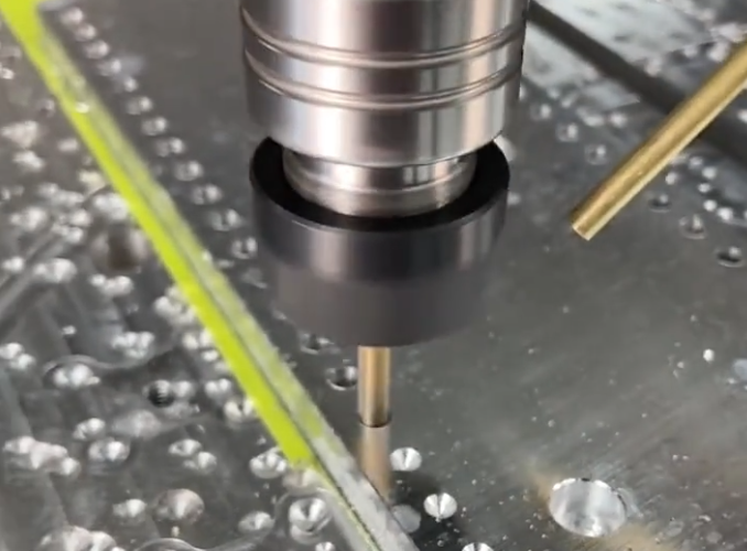
CNC Drilling and Tapping Centers
Dedicated CNC drilling and tapping centers are optimized for efficient production of many holes in plates, blocks and housings.
Key points:
High spindle speeds and rapid tool changes enable fast drilling, tapping and reaming cycles. These machines are often used in electronics, automotive and general industrial applications where a large number of threaded or clearance holes are required.
Other CNC Machining Processes
Beyond milling and turning, several related CNC processes are commonly used within a machining workflow:
CNC Grinding: Uses abrasive wheels to achieve very tight tolerances and superior surface finishes on hardened steels and precision components such as shafts, bearing seats and tooling.
CNC EDM (Electrical Discharge Machining): Includes wire EDM and sinker EDM for cutting hard materials and intricate features, sharp internal corners and narrow slots that are difficult or impossible to machine with rotating tools.
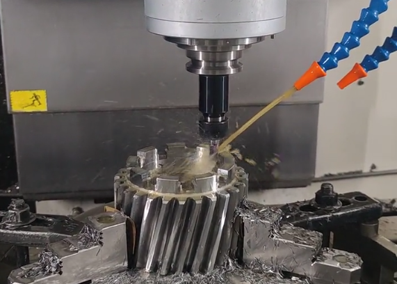
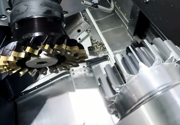
CNC Gear Cutting and Hobbing: Specialized CNC machines cut gear teeth, splines and similar profiles with consistent pitch, profile accuracy and surface quality.
CNC Machine Configurations and Axes
CNC machines vary in the number of motion axes and the arrangement of spindles and tables. These configurations significantly influence reachable geometries, cycle times and achievable precision.
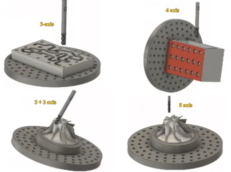
3-Axis Machining Centers
3-axis milling machines move the tool or table along X, Y and Z axes. They are widely used for:
Planar surfaces, pockets, slots, drilled holes, simple 3D contours and general prismatic parts.
They are typically the most cost-effective option for parts that do not require undercuts or features on multiple orientations.
4-Axis and 5-Axis Machining Centers
4-axis machines add a rotary axis (often a rotating table or fixture) to allow machining on multiple sides without manual repositioning. Typical uses include manifolds, impellers with moderate complexity and prismatic parts with side features.
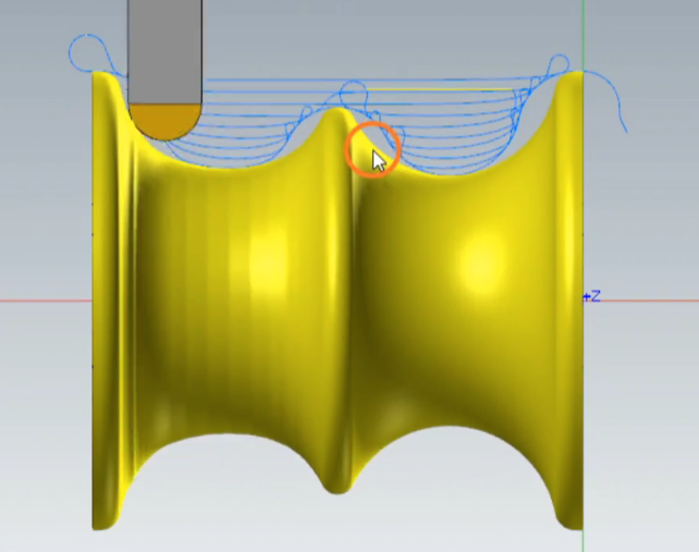
5-axis machines add another rotary axis, enabling the tool to approach the workpiece from nearly any direction. Advantages:
- Reduction in setups for complex multi-face parts
- Improved access to deep cavities and undercuts
- Better tool orientation, shorter tools and improved surface finish
5-axis machining is common in aerospace (blisks, turbine blades), medical (implants, orthopedic components) and high-precision molds and dies.
CNC Lathes: 2-Axis, Multi-Axis and Swiss-Type
Standard 2-axis CNC lathes feature X and Z axes. More advanced lathes may include:
Y-axis for offset milling and drilling, sub-spindles for machining both ends of a part, and live tooling turrets.
Swiss-type (sliding headstock) lathes support long, slender parts with excellent concentricity and productivity. They feed the bar stock through a guide bushing close to the cutting zone, minimizing deflection and vibration.
CNC Machining Materials Overview
CNC machining can process a broad range of metals and plastics. Material selection impacts mechanical performance, machinability, achievable tolerances and overall cost.
| Material Category | Examples | Typical Applications |
|---|---|---|
| Aluminum Alloys | 6061, 6082, 7075, 2024 | Structural components, enclosures, automotive parts, jigs and fixtures |
| Carbon & Alloy Steels | 1018, 1045, 4140, 4340 | Shafts, gears, tooling, machine elements, high-strength parts |
| Stainless Steels | 303, 304, 316, 17-4PH | Corrosion-resistant parts, food and medical equipment, marine components |
| Copper & Alloys | Copper, Brass, Bronze | Electrical components, fittings, fluid handling parts, decorative hardware |
| Tool Steels | D2, O1, A2, H13 | Molds, dies, cutting tools, wear-resistant inserts |
| Titanium Alloys | Grade 2, Ti-6Al-4V | Aerospace parts, medical implants, high strength-to-weight components |
| Engineering Plastics | ABS, POM (Delrin), Nylon, PC, PEEK, PTFE | Insulators, lightweight components, prototypes, chemical-resistant parts |
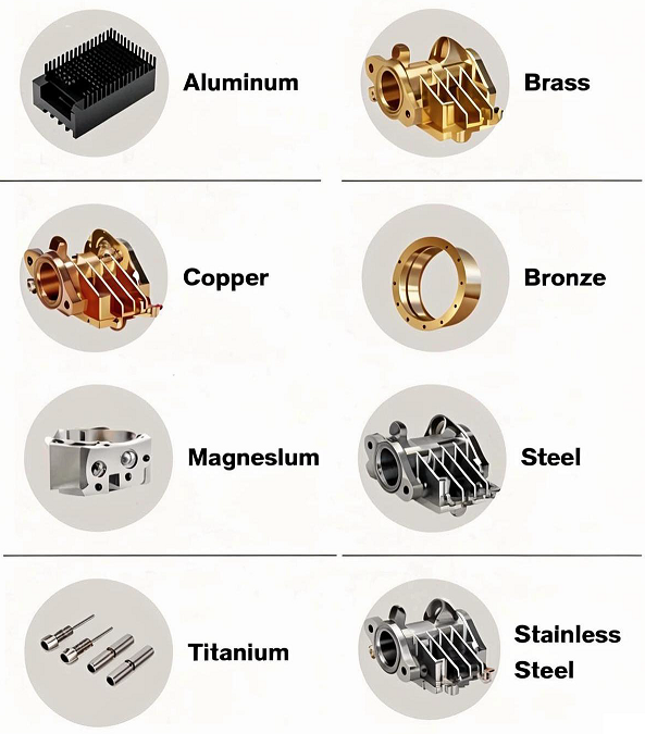
Machining Metals
Metals are frequently used where high strength, stiffness, wear resistance or conductivity are required.
Aluminum alloys:
Positive aspects include good machinability, low density, decent strength and availability in various tempers. 6061 is widely used for general applications; 7075 is preferred for high-strength structural components.
Carbon and alloy steels:
Offer high strength, good toughness and a range of heat treatments. However, machining harder grades may require rigid setups, suitable tooling and optimized parameters to control tool wear.
Stainless steels:
Provide corrosion resistance and elevated temperature performance. Austenitic grades like 304 and 316 may be more difficult to machine due to work hardening and lower thermal conductivity, requiring sharp tools and controlled cutting conditions.
Copper, brass and bronze:
Brass generally machines well with short chips and good surface finish, making it suitable for high-productivity operations. Copper’s high thermal conductivity and ductility demand careful parameter tuning to avoid built-up edges on tools.
Tool steels and hardened materials:
Often machined in the annealed state, then heat treated. Grinding or hard turning may be used after heat treatment to meet final dimensional and surface requirements.
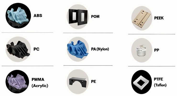
Machining Plastics
Engineering plastics are selected where low weight, electrical insulation, chemical resistance or noise reduction are needed.
Common examples:
ABS: Used for housings, prototypes and consumer goods, with good machinability and dimensional stability.
POM (Acetal/Delrin): Offers low friction, excellent dimensional stability and good machinability, useful for gears, bushings and precision mechanisms.
Nylon: Provides toughness and wear resistance, but may absorb moisture affecting dimensions.
PC (Polycarbonate): Transparent and impact resistant, used for protective covers and optical applications.
PEEK: High-performance plastic with excellent chemical resistance and temperature stability, suitable for demanding aerospace and medical parts.
When machining plastics, tool geometries, cutting speeds and heat generation must be controlled to avoid melting, warping and surface defects.
Dimensional Tolerances and Accuracy in CNC Machining
CNC machining can achieve tight tolerances and consistent repeatability when processes are correctly engineered.
Typical Tolerances
The achievable tolerances depend on machine capability, tool condition, material, part geometry and process setup. Typical ranges:
General commercial tolerances: ±0.10 mm to ±0.05 mm for most features on standard milling and turning operations.
Precision machining: ±0.025 mm or tighter, often with additional process control and inspection.
High-precision components: ±0.010 mm or smaller for critical features, using stable machines, temperature control and precision metrology.
Tolerance Considerations
Smaller tolerances usually result in higher costs due to lower batch throughput, more frequent inspection, potential tool changes and tighter process control.
Recommendations:
- Specify tight tolerances only where functionally necessary
- Apply geometric tolerancing (GD&T) for critical relationships such as coaxiality, perpendicularity and runout
- Group critical features close to common datums to minimize stack-up errors
Surface Finish in CNC Machining
Surface finish affects appearance, wear, friction, sealing performance and fatigue strength. It is influenced by cutting parameters, tool geometry, material and secondary finishing processes.
As-Machined Surface Roughness
Typical as-machined surface roughness (Ra) values:
Standard milling: approximately 1.6 – 3.2 µm Ra depending on tool size, feed and material.
Finishing passes with optimized conditions: around 0.8 – 1.6 µm Ra.
Turning operations on rigid setups can often achieve 0.8 – 1.6 µm Ra with appropriate inserts and finishing cuts.
Post-Machining Finishes
To achieve specific functional or aesthetic properties, additional finishing processes can be applied:
Mechanical finishes (e.g., sanding, bead blasting, polishing) to adjust texture and gloss.
Chemical and electrochemical treatments (e.g., anodizing for aluminum, passivation for stainless steel, plating) to enhance corrosion resistance and surface hardness.
Coatings (e.g., painting, powder coating, hard coatings) for color, wear resistance or specific surface properties.
Each added operation increases cost and lead time, so finishes should be selected to meet functional requirements without over-specifying the cosmetic appearance.
Workholding, Tooling and Setup Considerations
Process stability in CNC machining heavily depends on workholding and tooling strategies. Poor fixturing or tool selection can result in chatter, dimensional inaccuracy and surface defects.
Workholding Methods
Common methods:
Vices and clamps: Suitable for prismatic parts, often with soft jaws machined to match the part profile.
Chucks and collets: Used on lathes for round bar stock and turned parts.
Dedicated fixtures and jigs: Designed for specific parts, suitable for high-volume production where consistent positioning and quick loading are essential.
Vacuum fixtures: Used mainly for thin plate-like parts to avoid deformation from clamps.
When designing workholding, factors such as rigidity, repeatability, accessibility for tools and allowance for chip evacuation must be addressed.
Cutting Tools and Parameters
Cutting tools include end mills, drills, taps, reamers, inserts and special tools. Tool material (carbide, HSS, coated carbide, ceramics) and geometry (flute count, helix angle, rake angle) are chosen based on material and operation type.
Key parameters:
Spindle speed (rpm): Influences cutting speed and heat generation.
Feed rate (mm/min or inch/min, and per tooth feed): Impacts chip thickness, tool life and surface finish.
Depth of cut and step-over: Control material removal rate and cutting forces.
Coolant and lubrication: Assist chip evacuation, reduce heat and enhance surface quality, particularly in metals.
Optimization of these parameters aims for efficient material removal while protecting tool life and maintaining dimensional accuracy.
Design for CNC Machining
Designing parts with CNC machining in mind improves manufacturability and cost-efficiency while maintaining functional performance.
Geometry and Feature Design
Considerations:
Minimum feature size: Limited by tool diameter and rigidity. Very small holes or narrow slots may require specialized tools or secondary operations.
Internal radii: Sharp internal corners are challenging to machine; adding fillets with a radius larger than the tool radius reduces machining time and tool wear.
Wall thickness: Excessively thin walls can vibrate, deform or chatter, harming surface finish and accuracy.
Depth-to-diameter ratio of holes: Deep holes may require step drilling, specialized drills or reduced feed rates, which increases cycle time.
Accessibility: Features should be oriented to minimize tool overhang and avoid unreachable areas where possible.
Tolerance and Finish Specification
Applying uniform tight tolerances or highly cosmetic finishes throughout a part can substantially increase inspection, machining and finishing efforts.
Best practices:
Use different tolerance classes for functional and non-functional features.
Clear documentation of critical dimensions and surfaces on drawings helps focus process control and inspection.
Specify face flatness, parallelism and perpendicularity only where necessary for assembly or sealing performance.
Cost Structure of CNC Machining
CNC machining costs arise from material, machine time, tooling, setups, programming and overhead. Understanding these elements supports better quoting and cost optimization.
| Cost Element | Description | Impact on Total Cost |
|---|---|---|
| Material Cost | Raw stock price per kg or per bar/plate including scrap allowance | Varies with material type, part volume and buy-to-fly ratio |
| Machine Time | Time spent cutting, moving and changing tools | Major cost factor, influenced by part complexity and parameters |
| Setup and Programming | Time to program CAM, prepare fixtures, set tools and run initial parts | Spread over total quantity; significant for small batches |
| Tooling and Consumables | Cutting tools, inserts, fixtures, coolants and maintenance items | Higher for hard-to-machine materials and tight tolerances |
| Secondary Operations | Heat treatment, surface finishing, deburring, assembly | Adds direct cost and lead time to the base machining cost |
| Inspection and Quality Control | Measurement, documentation, first article inspection | Increases with tolerance tightness and regulatory requirements |
Material and Stock Utilization
Material cost is determined by the type of material, its form (bar, plate, forging, casting) and utilization.
Considerations:
Buy-to-fly ratio: The ratio between the purchased material weight and final part weight. Higher ratios indicate more waste and machining time.
Standard sizes: Using stock in standard diameters or plate thicknesses can reduce purchase price and lead time.
Nesting and blank preparation: Efficient cutting of blanks from plates or bars improves material utilization, especially for high volumes.
Machine Time and Cycle Time
Machine time is a function of cutting parameters, toolpaths, tool changes and non-cutting movements.
Factors increasing cycle time:
Complex 3D surfaces requiring fine step-overs and slow feed rates.
Deep cavities or features with limited tool access, forcing multiple roughing and finishing steps.
Frequent tool changes or repositioning, especially on machines with limited tool magazines.
Optimizing toolpaths (e.g., high-efficiency strategies) and consolidating operations on multi-axis or mill-turn machines can significantly reduce total cycle time.
Setup, Programming and Batch Size
Setup and programming costs are usually fixed per part number, regardless of quantity. Therefore, the unit cost depends strongly on the number of parts in the order.
For small batches or prototypes, the proportion of programming and setup in the total cost is high. For large batches, these costs are spread over many units, reducing the per-part contribution.
Reducing the number of setups per part through thoughtful design and machine selection also lowers overall manufacturing time and cost.
Tooling Wear and Hard-to-Machine Materials
Materials such as hardened steels, titanium alloys and nickel-based superalloys increase cutting forces and heat, leading to faster tool wear. In these cases, higher tooling costs and lower cutting speeds are typical.
Even for easily machinable materials, improper tool selection or process parameters can shorten tool life significantly, increasing costs and reducing process stability.
Secondary Processes and Finishing Costs
Processes such as heat treatment, grinding, anodizing, plating, painting and assembly can sometimes exceed the base machining cost, especially for corrosion-resistant or high-precision components.
When evaluating suppliers or comparing manufacturing routes, it is important to include all mandatory secondary operations in the cost analysis, not just the CNC machining time.
CNC Machining Cost Optimization
Systematic cost optimization balances functional requirements with manufacturing capabilities and constraints.
Design Optimization for Cost
Strategies include:
Eliminating unnecessary features that require specialized tools or multiple setups.
Standardizing hole sizes and thread types to reduce tool variety and setup complexity.
Increasing internal corner radii where possible to allow larger, more robust tools and faster milling operations.
Relaxing tolerances on non-critical features, reducing inspection frequency and process control efforts.
Process and Supplier Selection
Selecting the appropriate machine type (3-axis vs. 5-axis vs. mill-turn) and supplier with suitable equipment can significantly impact cost and quality.
Consider:
Supplier’s experience with specific materials and part types.
Availability of in-house secondary processes to avoid multiple outsourcing steps.
Capacity and lead times in relation to project schedules.
Addressing Typical Pain Points
Common difficulties in CNC machining projects include:
Dimensional deviations after heat treatment or surface finishing due to distortion.
Deformation of thin-walled parts caused by cutting forces or clamping pressure.
Surface defects such as chatter marks, burrs and tool marks requiring additional deburring and finishing steps.
Communication gaps between design and manufacturing teams regarding tolerance interpretation and inspection methods.
These issues can be mitigated through early design consultation, trial runs, process simulations where applicable and clear documentation of acceptance criteria.
CNC Machining Solutions: Precision, Materials, and Cost Efficiency with XCM
At XCM, we make CNC machining easier to understand and easier to use. Whether you need CNC milling, turning, drilling or complex 5-axis machining, our team helps you choose the right process, the right material and the most cost-effective path to production. From lightweight aluminum and stainless steel to tool steels, brass, copper and engineering plastics, we match materials to your performance and budget needs—explaining how each option impacts strength, finish and price. By combining engineering support, transparent quotations and optimized machining strategies, XCM reduces waste, shortens lead times and lowers unit cost without compromising precision. Partner with XCM to turn CNC machining from a technical challenge into a clear, predictable and profitable part of your supply chain.
FAQ
What is CNC machining?
CNC (Computer Numerical Control) machining is a manufacturing process where pre-programmed computer software controls machines such as mills, lathes, and routers to precisely remove material and shape parts.
What materials can be machined with CNC?
CNC machines can work with metals (aluminum, steel, titanium, brass), plastics (ABS, PEEK, nylon), composites, and sometimes ceramics depending on the tooling and machine capabilities.
What factors influence the cost of CNC machining?
Cost depends on material type, part complexity, size, tolerance requirements, surface finish, and production volume. Setup time and machine time also play a major role.
How do CNC machine types affect cost?
More advanced machines (e.g., 5-axis CNC) can produce complex parts but are more expensive to operate and maintain. Simple 3-axis machines cost less but have limitations in geometry and precision.
How can I reduce CNC machining costs?
Costs can be reduced by simplifying part geometry, selecting machinable materials, minimizing tight tolerances where unnecessary, optimizing batch size, and working with experienced CNC programmers.
