
CNC machining is a subtractive manufacturing method that uses computer-controlled machine tools to remove material from a solid workpiece. A systematic, step-by-step process is essential to achieve dimensional accuracy, repeatability, and efficient production. This guide explains each stage in detail, from design to finished parts.
What Is CNC Machining Workflow
The CNC machining workflow converts a digital design into a physical component through a chained sequence of digital and physical operations. At its core, the process integrates CAD modeling, CAM programming, and CNC machine execution, supported by measurement and quality assurance. The accuracy of the final part depends on the precision and consistency applied at each stage.
The complete workflow usually includes part design, material selection, process planning, toolpath generation, setup, cutting, inspection, and post-processing. Each step has defined inputs and outputs, enabling traceability and controlled adjustments.
Step 1: Part Design and Engineering Requirements
The workflow begins with a clear definition of the part’s functional requirements. This determines accuracy, tolerances, surface quality, and the manufacturing strategy.
Functional and Performance Requirements
- Define loads, stresses, and stiffness requirements.
- Identify mating components and interfaces (fits, alignments, sealing surfaces).
- Specify environmental conditions (temperature range, corrosion exposure, vibration).
Dimensional Accuracy and Tolerances
Establish realistic tolerances aligned with machine and process capability:
- General machined features: ±0.05 mm to ±0.1 mm.
- Precision fits and location features: ±0.005 mm to ±0.02 mm (depending on machine, fixturing, and inspection method).
- Geometric tolerances: flatness, parallelism, perpendicularity, position, runout, profile, and concentricity.
Surface Finish Requirements
Define surface roughness (Ra) and functional finishes:
Typical ranges:
- Roughing: Ra 3.2–12.5 μm.
- Semi-finishing: Ra 1.6–3.2 μm.
- Finishing: Ra 0.4–1.6 μm (down to 0.2 μm or better for critical surfaces).
Manufacturability Constraints
Design must account for machining realities:
Common constraints:
- Tool access: sufficient clearance for tool diameter and holder.
- Minimum radius in internal pockets to match cutter diameter.
- Wall thickness to prevent chatter and distortion.
- Standard hole sizes compatible with drills and reamers.
Step 2: Material Selection and Stock Definition
Material selection balances mechanical performance, machinability, cost, and availability. Stock definition sets the initial shape and size before machining.
Material Selection Criteria
Key properties considered:
- Mechanical: tensile strength, yield strength, hardness, elongation, fatigue resistance.
- Thermal: thermal expansion, conductivity, operating temperature.
- Chemical: corrosion resistance, oxidation behavior, compatibility with environment.
- Machinability: chip formation, tool wear, achievable surface finish.
Common CNC Machining Materials
| Material Group | Examples | Typical Use | Relative Machinability |
|---|---|---|---|
| Aluminum Alloys | Al 6061, 6082, 7075 | Lightweight structural parts, housings | Excellent |
| Carbon & Alloy Steels | C45, 4140, 4340 | Shafts, gears, high-strength components | Moderate to good |
| Stainless Steels | 304, 316, 17-4PH | Corrosion-resistant parts, medical, marine | Moderate to difficult |
| Copper Alloys | Brass, bronze | Fittings, valves, decorative, electrical | Good |
| Tool Steels | D2, H13, P20 | Molds, dies, wear components | Difficult, often pre-hardened |
| Plastics | ABS, POM, PEEK, PTFE | Insulators, lightweight components | Good but heat-sensitive |
Stock Form and Oversize Allowance
Stock forms include bar, plate, billet, casting, and forging. Oversize must allow for:
- Clamping and fixturing surfaces.
- Material removal for roughing, semi-finishing, and finishing.
- Distortion and allowance for final straightening or stress relief if needed.
Typical oversize ranges from 1–5 mm per side for small to medium parts, larger for heavy stock or high-distortion materials.
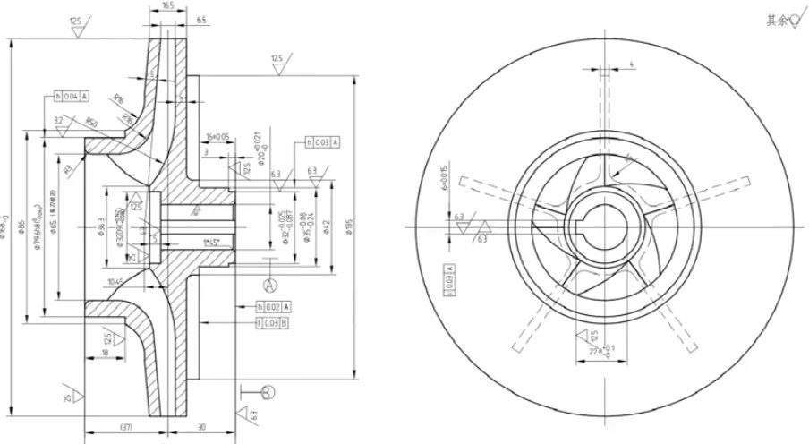
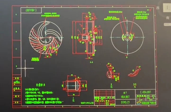
Step 3: CAD Modeling and Technical Drawings
CAD data defines geometry, while technical drawings define how that geometry will be inspected and interpreted.
3D CAD Modeling
Effective CAD models should:
- Contain complete solid geometry with correct radii, chamfers, draft angles if needed.
- Avoid unnecessary tiny features that complicate machining.
- Be fully constrained and parametric where possible to simplify design changes.
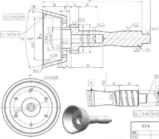
2D Drawings and GD&T
Technical drawings communicate:
- Critical dimensions and tolerances.
- Geometric dimensioning and tolerancing (GD&T) according to standards such as ISO or ASME.
- Datum structure (primary, secondary, tertiary datums) defining measurement references.
- Surface finish symbols and special notes (deburring, edge break, no sharp edges, etc.).
Data Formats and Exchange
Common formats:
- 3D: STEP, IGES, Parasolid, native CAD formats.
- 2D: PDF, DXF, DWG.
Consistency between 3D models and drawings is essential to avoid ambiguity.
Step 4: Process Planning and Operation Sequencing
Process planning defines how the part will be produced, in what sequence, and on which equipment. A well-structured sequence controls dimensional accuracy and minimizes setup time.
Defining Machining Strategy
Key considerations:
- Number of setups and orientations required to access all features.
- Use of single machine vs. multiple machines (e.g., mill-turn vs. separate lathe and mill).
- Top-down or datum-based strategy to establish and preserve reference surfaces.
Operation Sequencing
A typical sequence:
- Rough machining: remove bulk material, leave stock for finishing.
- Semi-finishing: stabilize geometry, prepare for finishing cuts.
- Finishing: achieve final dimensions and surface finishes.
- Drilling and tapping: may occur between roughing and finishing, depending on tolerance and risk of distortion.
Datum and Reference Strategy
Establishing stable datums early is critical. A common approach:
- Face and square one side to create a primary datum.
- Machine secondary surfaces to create additional datums.
- Reference all critical dimensions to these consistent datums throughout the process.
Step 5: Tooling Selection and Cutting Parameter Definition
Tool choice and cutting conditions directly affect productivity, tool life, and part quality.
Tool Type and Geometry
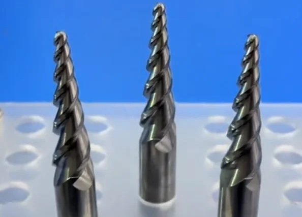
Common milling tools:
- End mills (2–6 flutes) for pockets, slots, contours.
- Face mills for large planar surfaces.
- Ball nose and bull nose mills for 3D surfaces.
- Chamfer mills for edges and deburring.
Common turning tools:
- External roughing and finishing inserts.
- Internal boring bars.
- Grooving, parting-off, threading tools.
Cutting Parameter Basics
| Material | Tool Type | Cutting Speed (Vc) | Feed per Tooth (fz) | Depth of Cut (ap) |
|---|---|---|---|---|
| Aluminum Alloys | Carbide end mill | 200–600 m/min | 0.05–0.25 mm/tooth | 1–3 × tool diameter (roughing) |
| Carbon Steel (Unhardened) | Carbide end mill | 80–250 m/min | 0.03–0.15 mm/tooth | 0.5–2 × tool diameter (roughing) |
| Stainless Steel | Carbide end mill | 60–180 m/min | 0.02–0.12 mm/tooth | 0.3–1.5 × tool diameter (roughing) |
| Tool Steel (Pre-hardened) | Carbide end mill | 50–160 m/min | 0.02–0.10 mm/tooth | 0.3–1 × tool diameter (roughing) |
| Plastics | Carbide end mill | 150–400 m/min | 0.03–0.20 mm/tooth | 0.5–2 × tool diameter (roughing) |
Values depend on tool coating, tool diameter, machine rigidity, and coolant use. Manufacturer catalogs provide specific recommended values.
Tool Life and Tooling Strategy
Tooling decisions should consider:
- Separate roughing and finishing tools to preserve edge sharpness for precision cuts.
- Indexable vs. solid tools based on batch size and cost.
- Coolant type (emulsion, oil, MQL, dry) according to material and tool.
Step 6: Workholding and Fixturing Design
Workholding determines how accurately and safely the workpiece is held during machining. Poor workholding is a frequent root cause of dimensional errors and vibration.
Workholding Options
Common systems:
- Vises and clamps for prismatic parts.
- Chucks and collets for cylindrical parts.
- Dedicated fixtures and pallets for high-volume or complex geometry.
- Modular fixturing systems for flexible changeover.
Fixturing Principles
Apply the 3-2-1 location principle where practical:
- Three points to locate the primary datum plane.
- Two points to locate the secondary datum edge.
- One point to locate the tertiary datum.
Additionally:
- Provide enough clamping force without deforming the part.
- Avoid clamping on finished surfaces where possible.
- Ensure chip evacuation and tool access around clamps and locators.
Thermal and Distortion Considerations
Thin walls and long parts may distort under clamping and cutting forces. Strategies include:
- Using support pads or sacrificial supports.
- Roughing with uniform wall thickness to balance stresses.
- Reclamping and re-referencing for critical finishing operations.
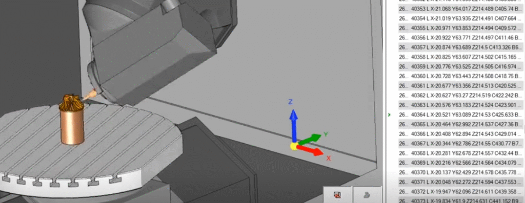
Step 7: CAM Programming and Toolpath Generation
CAM software translates CAD geometry into cutter paths that the CNC machine will follow.
Toolpath Types
Typical operations:
- Facing, contouring, and pocketing.
- Slotting, profiling, and rest machining.
- 3D surface finishing (parallel, spiral, scallop toolpaths).
- Drilling cycles (peck drilling, deep hole, reaming, tapping cycles).
Toolpath Strategy and Optimization
Considerations when creating toolpaths:
- Maintain constant tool engagement for predictable load.
- Use trochoidal or high-efficiency milling for harder materials and deep cavities.
- Avoid full-width slotting with deep axial cut unless machine and tool are sized accordingly.
- Control entry/exit paths to avoid dwell marks on critical surfaces.
Collision and Gouge Avoidance
CAM setup must define:
- Tool length, holder geometry, and safe clearances.
- Safe retract planes and approach points.
- Check surfaces and avoidance regions to protect finished features.
Step 8: Post-Processing and G-Code Generation
Post-processing converts CAM toolpaths into machine-specific G-code programs.
Post Processor Configuration
Each machine and control (e.g., Fanuc, Siemens, Heidenhain) requires a dedicated post processor configured for:
- Axis orientation and rotation direction.
- Tool change commands and reference positions.
- Work offset codes (e.g., G54–G59) and coordinate system conventions.
Program Structuring
Best practices:
- Organize programs into logical operations with clear comments.
- Use separate subprograms for repeated features where appropriate.
- Include spindle speeds, feed rates, coolant commands, and safe starts in each operation block.
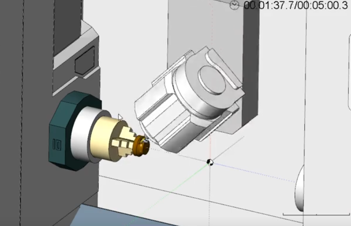
Verification Before Transfer
Within CAM, run simulation to check:
- Tool collisions with part, fixtures, and machine components.
- Overtravel beyond machine limits.
- Missing operations or unmachined areas.
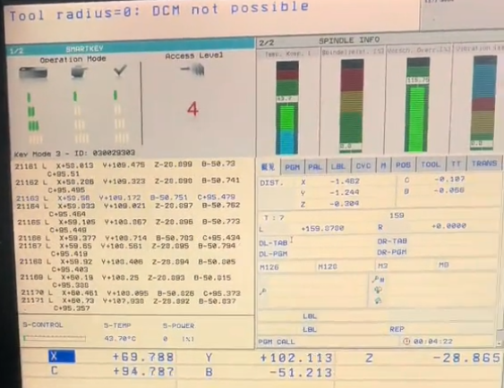
Step 9: Machine Preparation and Setup
Machine setup ensures that tools, workholding, and reference systems on the physical machine match the CAM plan.
Machine Readiness
Checks prior to machining:
- Machine warm-up cycles for spindle and axes (as specified by manufacturer).
- Coolant level, concentration, and filtration.
- Air supply pressure and quality for pneumatic systems.
Tool Loading and Length Measurement
Tasks:
- Load tools into designated tool pockets according to the tool list.
- Measure tool lengths and diameters using on-machine probes or presetters.
- Enter or import tool offsets into control, verified against CAM data.
Workpiece Installation and Alignment
Steps:
- Mount fixture or vise and tighten per torque recommendations.
- Align fixture using dial indicator, edge finder, or probing.
- Clamp the workpiece according to the fixturing plan, ensuring repeatable positioning.
Step 10: Dry Run and Program Verification on the Machine
On-machine verification reduces risk of crashes and scrap during initial runs.
Dry Run Methods
Common approaches:
- Graphics or simulation mode on the control, if available.
- Single-block execution with feed override turned down.
- Running the program with the spindle off and tool elevated above the workpiece.
Key Checks During Dry Run
- Correct program loaded and correct work offset (e.g., G54) active.
- Tool changes occur as expected and in safe position.
- No unexpected axis motions toward fixtures, clamps, or machine limits.
Adjustments Before Cutting
Adjustments may include:
- Updating safe approach and retract positions.
- Correcting work offset values or tool lengths.
- Modifying feed rates or spindle speeds where machine behavior indicates risk.
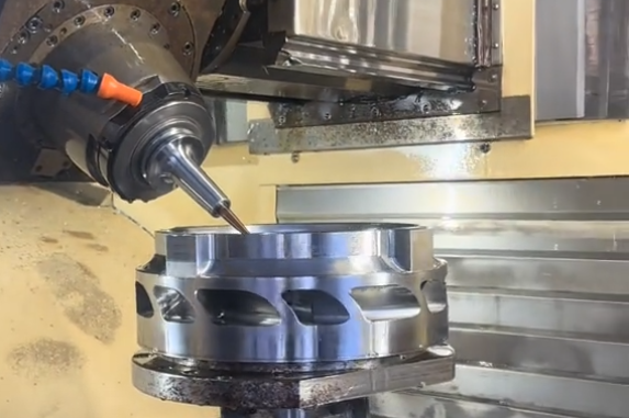
Step 11: Rough Machining Operations
Roughing removes the majority of excess material at high material removal rates while leaving a uniform stock allowance for later operations.
Roughing Objectives
- Maximize chip volume per unit time within machine power and rigidity limits.
- Maintain controlled part temperature and avoid excessive work hardening.
- Leave consistent stock for semi-finishing to stabilize dimensions.
Typical Roughing Parameters
Roughing usually uses:
- High axial depth of cut (ap) and moderate radial engagement (ae).
- Moderate to high feed rates (mm/min) with feed per tooth tuned to avoid chatter.
- Coolant or air blast for chip evacuation, especially in deep cavities.
Chip Control and Tool Wear
Effective roughing requires:
- Chip evacuation to prevent recutting and tool chipping.
- Periodic tool inspection or scheduled tool changes for long runs.
- Monitoring spindle load to detect abnormal cutting conditions.
Step 12: Semi-Finishing and Feature Machining
Semi-finishing refines the geometry after roughing, prepares surfaces for finishing passes, and completes non-critical features.
Semi-Finishing Strategy
- Use lower depth of cut and lower engagement compared to roughing.
- Remove remaining stock uniformly to reduce residual stress and distortion.
- Stabilize thin walls and slender features before final finishing.
Feature Machining in This Stage
Operations that may be completed at semi-finishing stage:
- Non-critical pockets, slots, and chamfers.
- Pre-drilling and countersinking for later tapping or reaming.
- Pre-machining of bores to leave small allowance for boring or reaming.
Intermediate Inspection
Semi-finished parts are often checked for:
- Critical distances between datums and major features.
- Wall thickness and flatness of important surfaces.
- Conformance to stock allowance planned for final finishing.
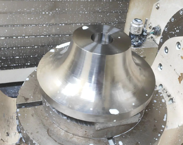
Step 13: Finishing Operations for Final Dimensions
Finishing operations achieve final dimensions, tolerances, and surface finishes.
Finishing Parameters
Typical finishing settings:
- Small radial and axial depths of cut to minimize cutting forces.
- Higher cutting speeds for improved surface finish (within tool limits).
- Moderate feed per tooth to avoid tool marks while preventing rubbing.
Dimensional Control
Finishing strategies to ensure dimensional accuracy:
- Use sharp, dedicated finishing tools with minimal runout.
- Maintain consistent coolant flow and temperature to reduce thermal variation.
- Sequence finishing cuts to limit heat accumulation on critical areas.
Surface Finish Requirements
Finishing passes aim for specified Ra values and typically avoid dwell marks and chatter. In some cases, overlapping passes with small step-over and optimized toolpath directions are used to control visual patterns on visible surfaces.
Step 14: Special Operations (Drilling, Tapping, Boring)
Holes and cylindrical features are frequent sources of functional constraints and require carefully selected methods.
Drilling
Considerations:
- Select appropriate point angle and flute geometry for material.
- Use peck drilling cycles for deep holes (depth > 3–5 × diameter).
- Provide adequate coolant, especially for deep or small-diameter holes.
Tapping
Key aspects:
- Use correct tap type (spiral point, spiral flute, forming tap) and pitch.
- Set spindle speed and feed to match thread pitch in rigid tapping cycles.
- Control hole size before tapping according to standard tapping drill charts.
Boring and Reaming
Used to achieve precise hole diameters and alignment:
- Boring bars correct position and roundness with adjustable diameters.
- Reamers provide tight diameter control and improved surface finish.
- Finishing hole operations often occur late in the process to avoid misalignment due to earlier distortion.
Step 15: In-Process Measurement and Quality Control
In-process measurement monitors part quality during machining and allows timely corrections.
On-Machine Measurement
Methods:
- Touch probes for automatic measuring of features between operations.
- Tool probes for automatic tool length and wear compensation.
- Use of macros to adjust work offsets based on measured deviations.
Manual In-Process Checks
Common instruments:
- Calipers and micrometers for basic dimensions.
- Bore gauges for internal diameters.
- Height gauges and gauge blocks on surface plates for critical heights.
Control Plan Integration
An effective control plan defines:
- Which dimensions are checked at which stage of machining.
- Sampling frequency (e.g., every part, first-off, periodic checks for batches).
- Reaction plan if a dimension is out of tolerance (tool change, offset correction, process review).
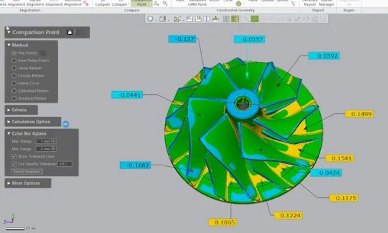
Step 16: Final Inspection and Dimensional Verification
Final inspection verifies that the finished part meets all drawing and specification requirements.
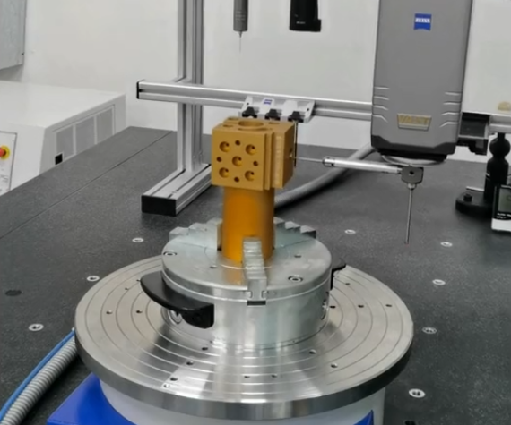
Dimensional Inspection
Common tools and methods:
- Coordinate Measuring Machine (CMM) for complex geometry and GD&T evaluation.
- Manual gauges (plug, ring, thread gauges) for standard features.
- Optical measurement and surface roughness testers for fine details.
Documentation and Traceability
Records may include:
- Inspection reports with measured values and tolerances.
- Material certificates (chemical composition, mechanical properties).
- Process logs documenting machine, tool, and program versions used.
Acceptance Criteria
Parts are accepted or rejected based on explicit criteria:
- All critical and major characteristics within tolerance.
- No functional defects such as cracks, deformation, or unacceptable surface flaws.
- Compliance with customer-specific requirements or industry standards.
Step 17: Deburring, Edge Finishing, and Cleaning
Deburring and cleaning ensure the part is safe to handle, fits correctly, and does not carry contamination into downstream assemblies.
Deburring Techniques
Methods include:
- Manual deburring with files, scrapers, and abrasive tools.
- Machine deburring passes using chamfer tools or ball end mills.
- Mass finishing processes such as tumbling or vibratory finishing for high volumes.
Edge Specifications
Edges can be specified as:
- Sharp edges (only where functionally required).
- Broken edges with specified chamfer (e.g., 0.2–0.5 mm × 45°).
- Rounded edges with specified radius for improved fatigue performance or safety.
Cleaning Processes
Cleaning removes cutting fluids, chips, and particulates. Typical methods:
- Ultrasonic cleaning in aqueous solutions.
- Solvent cleaning for oils and greases where compatible.
- High-pressure air or coolant flushing to remove chips from internal features.
Step 18: Post-Machining Treatments and Assembly Readiness
Post-machining treatments adjust material properties or surface characteristics and prepare the part for assembly or shipment.
Heat Treatment
Common processes:
- Hardening and tempering to increase strength and wear resistance.
- Solution treatment and aging for precipitation-hardening alloys.
- Stress relief to reduce residual stresses after heavy machining.
Surface Treatments and Coatings
Typical treatments:
- Anodizing for aluminum to improve corrosion resistance and surface hardness.
- Plating (zinc, nickel, chrome) for corrosion and wear resistance.
- Conversion coatings and passivation for steel and stainless steel.
Assembly Preparation
Tasks before assembly or shipment:
- Final cleaning after treatments to remove residues.
- Light oiling or protective coatings for corrosion-sensitive parts.
- Marking and labeling with part numbers, batch codes, and orientation marks if required.
Common Issues and Practical Considerations in CNC Machining
Several recurring issues can affect CNC machining quality and productivity. Addressing them systematically is essential for reliable production.
Dimensional Inaccuracy and Tolerance Issues
Causes:
- Thermal growth of machine or workpiece during long runs.
- Improper tool length or diameter compensation.
- Fixture misalignment or workpiece movement under cutting forces.
Mitigation:
- Allow machine warm-up and maintain stable shop temperature where possible.
- Verify offsets regularly and use on-machine probing to update them.
- Optimize clamping positions and reduce cutting forces near weak areas.
Chatter, Vibration, and Poor Surface Finish
Causes:
- Insufficient rigidity in setup, tool, or machine.
- Inappropriate combination of spindle speed, feed, and depth of cut.
- Excessive tool overhang or worn tools.
Mitigation:
- Shorten tool stick-out and use more rigid holders.
- Adjust spindle speed to move away from resonance ranges.
- Reduce radial engagement or use different tool geometry to stabilize cutting.
Tool Wear and Breakage
Causes:
- Cutting parameters exceeding tool material capabilities.
- Inadequate cooling or chip evacuation, especially in deep pockets or holes.
- Incorrect tool for material (e.g., using wrong coating or geometry).
Mitigation:
- Align cutting parameters with tool manufacturer data.
- Use through-coolant tools or improved coolant delivery.
- Select suitable tool grade and coating for the specific material group.
Chip Management and Machine Cleanliness
Issues:
- Chips accumulating in pockets, causing recutting and surface damage.
- Chips interfering with tool changes and probing operations.
- Blocked coolant nozzles or filters reducing cooling effectiveness.
Mitigation:
- Plan toolpaths and coolant jets to promote chip evacuation.
- Use chip conveyors and periodic cleaning routines.
- Monitor and maintain coolant filters and levels.
Programming and Setup Errors
Issues:
- Wrong work offset or coordinate system in G-code.
- Mismatched tool numbers between CAM and machine.
- Missing or incorrect safety moves, leading to potential collisions.
Mitigation:
- Standardize naming conventions and setup sheets linking CAM and machine data.
- Use checklists for first-article setups.
- Perform thorough simulation and dry run with safe overrides.
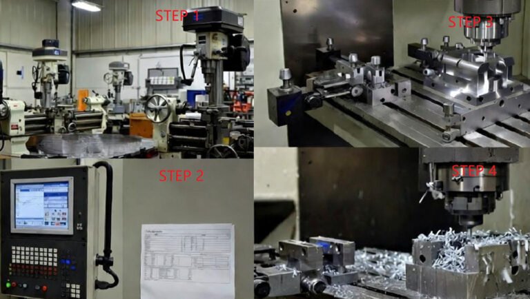
How-To: 4 Main Steps of CNC Machining
Step 1: Design the Part (CAD – Computer-Aided Design)
In this step, you:
Define exact dimensions and tolerances
Select material type (aluminum, steel, plastic, etc.)
Design holes, curves, threads, and surfaces
Goal: Create an accurate 2D or 3D digital model that the CNC machine can follow.
Step 2: Convert Design to Machine Code (CAM Programming)
In this step, you:
Choose cutting tools (drills, end mills, etc.)
Set speeds, feed rates, and cutting depth
Generate the toolpaths
Export the G-code file
Goal: Turn the design into precise machine instructions.
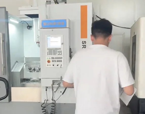
Step 3: Set Up the CNC Machine
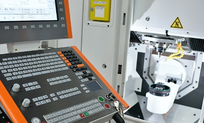
This includes:
Loading the correct cutting tools
Securing the raw material (workpiece) to the machine bed
Setting the machine’s zero point (X, Y, Z origin)
Uploading the G-code program
Goal: Ensure everything is aligned, locked, and ready for safe, accurate machining.
Step 4: Machine the Part & Inspect
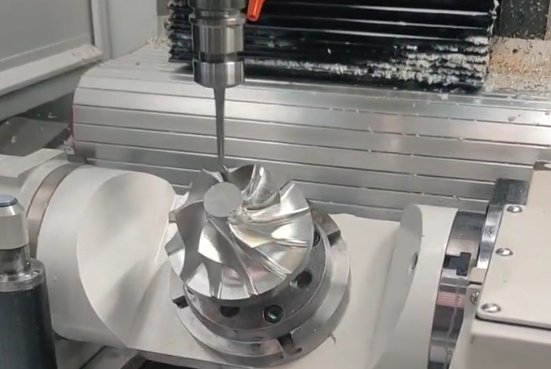
During this step:
Tools remove material layer by layer
Coolant may be applied to prevent overheating
The part is shaped with high precision
Final inspection and quality check are performed using calipers, micrometers, or CMM machines
Goal: Produce a finished, accurate, and high-quality part.
FAQ About the CNC Machining Process
What are the basic step-by-step stages of a CNC machining project?
Typical stages are: (1) design & CAD model, (2) material selection, (3) CAM programming & toolpath generation, (4) fixture/clamp setup, (5) CNC machining (roughing → finishing), (6) deburring & secondary operations, (7) inspection/quality control, (8) surface treatment/finishing, (9) packing & shipping.
What are the main stages of the CNC machining process?
The main stages are part design, material selection, CAD modeling and drawing creation, process planning, tooling and fixturing design, CAM programming, post-processing to G-code, machine setup, roughing, semi-finishing, finishing, special operations such as drilling and tapping, in-process inspection, final inspection, deburring and cleaning, and any required post-machining treatments such as heat treatment or coating.
How accurate can CNC machining be?
With a stable machine, proper setup, and controlled environment, CNC machining can routinely achieve tolerances in the range of ±0.01 mm to ±0.005 mm for many features. Tighter tolerances are possible for specific applications when the process is carefully optimized, although this may increase machining time and inspection requirements. Actual achievable accuracy depends on material, part geometry, fixturing, cutting parameters, and measurement methods.
How do I reduce machining costs?
Simplify geometry, avoid extremely tight tolerances where unnecessary, group features for fewer setups, choose machinable materials, design for standard tooling and stock sizes, and order larger quantities to amortize setup costs.
