
Overview of CNC Machining for Valve Parts
CNC machining is a primary manufacturing method for metal and plastic valve components that require high dimensional accuracy, leak-tight sealing surfaces, and consistent performance under pressure and temperature. It is widely used for industrial valves, oil and gas valves, hydraulic and pneumatic valves, process control valves, sanitary valves, and custom valve assemblies.
By using computer numerical control equipment, complex valve geometries can be produced with repeatable accuracy, including intricate internal passages, precision sealing faces, and fine threads for connections. CNC machining is suitable for both prototype and series production, supporting small batches, high-mix low-volume, and large-volume valve manufacturing.
Typical Valve Components Produced by CNC Machining
Most critical valve parts can be manufactured or finished using CNC turning centers, machining centers, and multi-axis equipment. Common components include:
- Valve bodies and bonnets
- Valve stems and spindles
- Balls, plugs, and discs
- Seats, rings, and cages
- Glands, caps, and covers
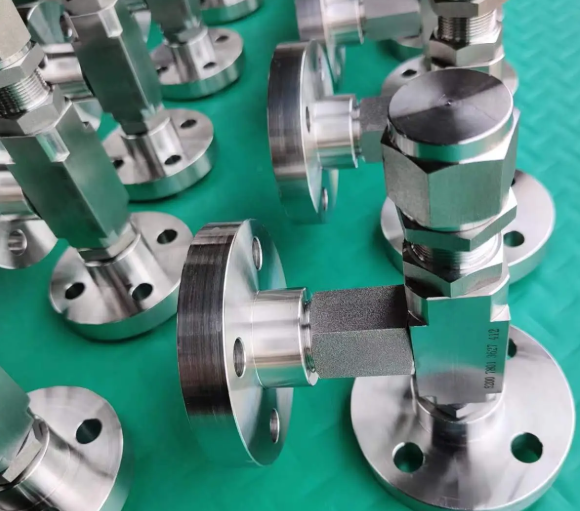
- Flanges, adapters, and manifolds
These parts must work together to ensure correct flow regulation, sealing, and mechanical strength. The choice of machining process for each component is based on size, geometry, material, and required tolerances.
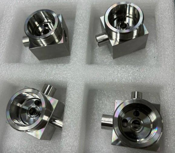
Valve Bodies and Bonnets
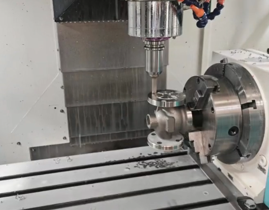
Valve bodies and bonnets form the main pressure-containing envelope. They often start from castings or forgings and are finished by CNC machining to achieve accurate dimensions, machined faces, and internal cavities. Key operations include boring of flow passages, machining of flange faces, drilling of bolt circles, threading of ports, and machining of sealing grooves and locating surfaces.
Valve Stems and Spindles
Valve stems are typically produced by CNC turning followed by milling operations for flats, keyways, or drive features. They require tight dimensional control for diameter, concentricity, and straightness. Surface finish and hardness in contact areas are important for wear resistance and reliable actuation.
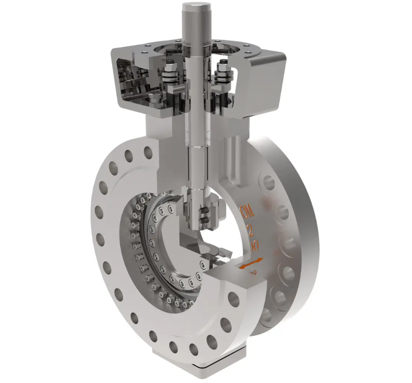
Balls, Plugs, Discs, and Seats
Balls and plugs are usually machined on CNC lathes or multi-axis machines, then ground or lapped to reach very fine surface finishes on sealing surfaces. Discs and seats may require contour milling, precision boring, and lapping to ensure accurate contact geometry and leak-tight sealing under specified pressure.
Materials for CNC-Machined Valve Parts
Valve components must resist pressure, flow-induced erosion, corrosion, and sometimes high temperature. CNC machining supports a wide range of metals and plastics used in valve manufacturing. Material selection depends on media, pressure class, temperature, and industry specifications.
| Material Category | Typical Grades | Main Applications in Valve Parts |
|---|---|---|
| Carbon & Low Alloy Steels | A105, A216 WCB, A350 LF2, 4140 | Bodies, bonnets, flanges for general service and moderate temperatures |
| Stainless Steels | 304/304L, 316/316L, 410, 420, 17-4PH | Corrosion-resistant bodies, stems, balls, trim for chemical and food processing |
| High Alloy & Duplex Steels | Duplex 2205, Super Duplex 2507, Alloy 20 | Severe corrosion environments, offshore, sour service components |
| Nickel Alloys | Inconel 625, 718; Monel 400; Hastelloy C-276 | High temperature and highly corrosive service trims and critical internals |
| Copper Alloys | Brass, Bronze, Aluminum bronze | Marine valves, low-pressure water and HVAC components, seat rings |
| Tool Steels & Hard Alloys | D2, H13, Stellite overlays | Erosion-resistant trims, seats, and throttling elements |
| Engineering Plastics | PTFE, PEEK, PVDF, Nylon, Acetal | Seats, seals, bushings, liners for low friction and chemical resistance |
Machinability varies significantly among these materials. For example, free-machining brass is relatively straightforward to cut, while duplex stainless steel and nickel-based alloys require optimized cutting parameters, rigid setups, and suitable tool materials to maintain dimensional accuracy and surface quality.
Machining Processes Used for Valve Parts
CNC machining for valve components combines several processes, each suited to particular geometries and tolerances. The manufacturing route is usually designed to minimize setups, ensure stable clamping, and preserve critical sealing surfaces.
CNC Turning
CNC turning is widely used for stems, balls, plugs, rings, and many symmetrical parts. Operations include facing, turning, grooving, threading, and parting-off. For valve components, turning may be used in the following ways:
- Rough and finish turning of valve stem diameters in one or more setups
- Profile turning of balls and plugs before finishing operations
- Internal turning and boring of cylindrical cavities in bodies and sleeves
Modern CNC lathes may include sub-spindles and live tooling to perform cross-drilling, milling of flats, and slotting operations within one machine cycle.
CNC Milling and Machining Centers
Vertical and horizontal machining centers are used to produce complex features on valve bodies, bonnets, manifolds, and flanges. Typical milling operations include:
Face milling of gasket surfaces, contour milling of external shapes, drilling and tapping of ports and bolt holes, pocketing and slotting of internal flow passages or cavities, and chamfering and deburring of edges. Multi-face machining fixtures are often used to machine several sides of a valve body in a single setup, which improves positional accuracy and reduces cumulative errors.
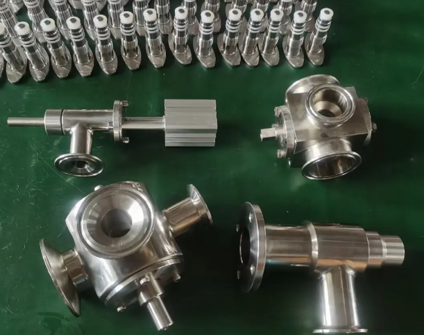
Multi-Axis and Mill-Turn Machining
Multi-axis machines and mill-turn centers combine functions of turning and milling with additional rotary and tilt axes. They are particularly useful for:
Machining complex ball valve bodies with intersecting ports and angled passages, producing integral manifolds with multiple connections, and machining offset or eccentric features in control valves without multiple re-clamping operations. By reducing the number of setups, these machines can improve repeatability of critical dimensions and lower the risk of alignment errors between internal and external features.
Drilling, Boring, and Reaming
Valve components often include multiple through-holes, cross-holes, and precision bores. Drilling is used for initial hole creation, boring for achieving accurate diameters and concentricity, and reaming for high-precision fits when needed. In valve manufacturing, these operations support functions such as stem guides, seat locations, and flow passages. Controlled feed rates and coolant supply are important to prevent deviation and maintain straightness in deep holes.
Thread Cutting and Tapping
Internal and external threads on valve connections must meet relevant standards (e.g., NPT, BSP, metric, or UN). Threads may be produced by single-point CNC threading, rigid tapping, or thread milling. For pressure-containing parts, consistent thread form, flank angle, and root finish are important to ensure reliable sealing and assembly.
Grinding, Lapping, and Honing
While not always performed on CNC equipment, grinding and lapping are critical finishing processes for many valve components. Balls, plugs, and seats often require ultra-smooth surfaces and precise geometry. These operations can reduce surface roughness to levels such as Ra 0.2 µm or finer where specified, which helps achieve bubble-tight or low-leakage performance. Honing may be used to refine bores in valve bodies or sleeves to achieve tight diameter tolerances and improved roundness.
Tolerances and Surface Finish Requirements
Valve components must meet specific tolerances to ensure sealing, alignment, and mechanical strength. The tolerances depend on valve size, pressure rating, and application, but CNC machining is capable of achieving fine levels of precision when properly controlled.
Dimensional Tolerances
Typical ranges for machined valve parts may include:
- General machined features: ±0.05 mm to ±0.1 mm
- Critical diameters on stems and guides: ±0.01 mm to ±0.02 mm
- Bore diameters for seats and guides: ±0.01 mm to ±0.03 mm
- Flatness on gasket surfaces: within 0.03 mm to 0.05 mm over specified area
- Positional tolerances for bolt circles and ports: typically within 0.05 mm to 0.1 mm depending on size
Exact figures depend on design drawings, applicable standards, and measurement capability, but CNC equipment with appropriate fixturing can routinely achieve these ranges.
Surface Roughness
Surface finish requirements vary across different areas of a valve:
Sealing faces for gaskets or metal-to-metal contact may require roughness values such as Ra 1.6 µm, 0.8 µm, or finer, depending on gasket type and leakage criteria. Stem sliding surfaces, guide bores, and packing areas generally need smooth finishes to reduce wear and friction. Flow passages may be machined to moderate roughness levels, with improved finish beneficial in reducing pressure losses and buildup of deposits.
Geometric Tolerances
Beyond linear dimensions, geometric tolerances are essential for valve reliability. Examples include roundness and cylindricity for stems and bores, perpendicularity between flange faces and stem axes, concentricity of sealing surfaces with respect to the flow axis, and parallelism between gasket faces and reference planes. CNC machining, combined with controlled setups and appropriate measuring equipment, helps keep these tolerances within specified limits.
Quality Control and Inspection of Valve Parts
Quality control in CNC machining of valve components covers raw material verification, in-process inspection, and final dimensional and functional checks. Consistent quality is necessary to meet pressure, leakage, and safety requirements in industries such as oil and gas, chemical processing, power generation, and water treatment.
Dimensional Inspection Methods
Dimensional inspection may involve micrometers, calipers, bore gauges, plug gauges, thread gauges, height gauges, and surface plates for routine checks. For critical surfaces and complex geometries, coordinate measuring machines (CMM) are frequently used to verify dimensions, geometric tolerances, and alignment between internal and external features.
Surface and Material Verification
Surface roughness meters are used to confirm finishing levels on sealing faces and sliding surfaces. Material certificates and positive material identification (PMI) may be required for critical applications to ensure correct alloy and mechanical properties. Hardness testing, such as Rockwell or Brinell, may be applied to verify heat-treated parts like hardened stems or trim components.
Leakage and Pressure-Related Checks
Although leak and pressure tests are usually performed on complete valve assemblies, certain machined parts may undergo localized tests, such as air leakage tests on machined weld overlays or seat ring assemblies. Machined surfaces must be free from defects such as deep scratches, nicks, or porosity that could cause leakage paths or stress concentration points.
Standards, Specifications, and Compliance
CNC-machined valve components must comply with applicable design, material, and testing standards. While design codes apply to the whole valve assembly, the machining processes and tolerances are often defined to support compliance with these requirements.
Common standards affecting valve components include dimensional standards for flanges and connections, materials specifications for pressure-containing parts, and testing criteria for pressure and leakage performance. The manufacturing documentation typically includes drawings with tolerances, surface finish symbols, and notes that align machining requirements with those standards.
Design for CNC Machining of Valve Parts
Design decisions have a significant impact on machining efficiency, cost, and quality. Adapting valve component designs to CNC machining capabilities can reduce production time and improve consistency.
Geometry Considerations
Designers can reduce complexity by using features that are compatible with standard tools, such as avoiding unnecessary undercuts, extremely deep narrow pockets, and non-standard thread forms. Providing adequate access for cutting tools to reach internal surfaces simplifies programming and reduces the number of setups required.
Wall Thickness and Machining Allowances
For cast and forged bodies, machining allowances should be specified so that final machining removes surface irregularities and meets dimensional requirements without excessively reducing wall thickness. Uniform wall thickness where possible helps maintain dimensional stability during machining and reduces distortion from clamping or residual stresses.
Tolerance Allocation
Critical features such as sealing surfaces and alignment bores should have tolerances that reflect their functional importance, while non-critical external surfaces can tolerate broader limits. Appropriate tolerance allocation allows cost-effective machining while achieving necessary performance. Overly tight tolerances on non-critical areas can increase cycle times and inspection effort without practical benefit.
Material and Heat Treatment
When parts require heat treatment for strength or hardness, the sequence of machining and heat treatment should be planned. Rough machining may be done pre-heat-treatment, with finish machining after to correct any distortion. Designers should consider the machinability of selected materials when specifying alloys and hardness levels for stems, seats, and other wear parts.
Production Planning and Process Flow
Efficient CNC machining for valve parts requires structured process planning. The process flow typically covers raw material preparation, rough machining, semi-finishing, finishing, and secondary operations.
| Stage | Main Operations | Key Objectives |
|---|---|---|
| 1. Pre-Machining | Receiving of casting/forging, cleaning, marking, initial inspection | Verify material, identify part, confirm allowance and visible defects |
| 2. Rough Machining | Rough facing, rough boring, rough milling of external surfaces | Establish reference surfaces, remove excess stock, stabilize structure |
| 3. Semi-Finishing | Semi-finish milling of gasket faces, drilling of ports, rough threading | Bring dimensions near final size, prepare for precision finishing |
| 4. Heat Treatment (if required) | Stress relieving or other specified treatments | Reduce residual stresses, improve mechanical properties |
| 5. Finish Machining | Finish boring, finish milling of sealing faces, final threading | Achieve final tolerances and surface finishes |
| 6. Deburring and Cleaning | Deburring edges, removing chips from internal passages, cleaning | Prevent contamination and assembly issues |
| 7. Final Inspection | Dimensional checks, visual inspection, documentation | Confirm compliance with drawings and specifications |
The exact sequence varies with part type and internal procedures, but a structured flow minimizes rework and ensures traceability.
Common Issues and Practical Considerations
When machining valve parts, several practical aspects must be handled to maintain quality and reliability.
Distortion and Dimensional Stability
Thin walls, asymmetric geometries, and residual stresses from casting or forging can cause distortion during machining. To reduce this, process planners may use intermediate stress-relief operations, balanced material removal, and optimized clamping strategies. Rough and semi-finish machining followed by a stabilization period before finishing can also improve dimensional stability.
Tool Wear and Surface Integrity
Hard and tough alloys used in valves can lead to accelerated tool wear. Inadequate cutting conditions may cause surface work-hardening, micro-cracking, or rough finishes that are not acceptable on sealing surfaces. Controlled cutting speeds, feeds, and coolant application are required, along with appropriate tool geometries and coatings.
Deburring and Cleanliness
Chips and burrs trapped in internal passages or around sealing edges can cause assembly problems, leakage paths, or contamination of process fluids. Effective deburring strategies and thorough cleaning of machined parts are essential, especially in hydraulic, pneumatic, and sanitary valve applications. Particular attention is needed for cross-holes and blind cavities.
Cost Factors in CNC Machining of Valve Parts
The cost of machined valve components is influenced by material, complexity, tolerances, and production volume. Key drivers include machine time, tooling consumption, setup effort, and inspection requirements. Design decisions that simplify fixturing, standardize features, and align tolerances with functional needs can significantly influence overall manufacturing cost.
Batch size also affects cost distribution. For small quantities or specialized valves, flexible CNC machining offers advantages because it avoids the need for dedicated tooling. For larger volumes, process optimization and standardized setups help to reduce cycle times and improve throughput.
Applications of CNC-Machined Valve Parts
CNC-machined valve components are used in a wide spectrum of industries where controlled flow and reliable sealing are required. Typical application sectors include:
- Oil and gas transmission and processing
- Chemical and petrochemical plants
- Power generation, including steam and cooling water systems
- Water and wastewater treatment facilities
- Food, beverage, and pharmaceutical processing
- HVAC, building services, and general industrial systems
Each sector may specify particular standards for materials, inspection, and documentation, which CNC machining processes can support through controlled production and traceable quality records.
Conclusion
CNC machining plays a central role in producing valve parts that meet stringent requirements for dimensional accuracy, surface finish, and material integrity. Through appropriate selection of materials, machining processes, tolerances, and inspection methods, manufacturers can produce valve components that perform reliably across a wide range of pressures, temperatures, and media. Well-designed CNC machining routes support both prototype development and volume production, providing repeatability, flexibility, and compatibility with industry standards.
