
CNC grinding is a core finishing process in modern manufacturing, used to achieve high dimensional accuracy, tight tolerances, and superior surface finishes on metal and non‑metal components. This guide explains CNC grinding principles, equipment, tooling, setup, parameters, programming, process optimization, and quality control for stable production.
Fundamentals of CNC Grinding
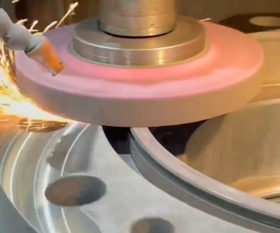
CNC grinding is a subtractive machining process where a rotating abrasive wheel removes material from a workpiece under CNC control. The process uses many cutting edges (abrasive grains) that act simultaneously, enabling high accuracy and fine surfaces.
Key elements:
- High‑speed rotating grinding wheel with bonded abrasives
- Controlled relative motion between wheel and workpiece via CNC axes
- Coolant supply to control heat, flush chips, and improve wheel life
- Precision workholding to maintain location and geometry
Main application areas include precision shafts, bearing seats, hydraulic components, cutting tools, molds, dies, and high‑hardness parts after heat treatment.
Major CNC Grinding Process Types
Different CNC grinding processes are selected based on part geometry, material, accuracy, and productivity requirements.
Cylindrical Grinding
Cylindrical grinding removes material from external or internal cylindrical surfaces.
Common modes:
- External cylindrical (OD) grinding: between centers or chucking
- Internal cylindrical (ID) grinding: internal bores, seats
- Universal grinding: combination of OD, ID, and face grinding in one setup
Typical features: shafts, spindles, pins, sleeves, bushings, bearing journals, and bores. Cylindrical grinding is widely used after heat treatment to correct distortion and achieve final size and roundness.
Centerless Grinding
Centerless grinding machines the outer surface of a cylindrical workpiece without using centers or chucks. The workpiece is supported between a grinding wheel and a regulating wheel, resting on a work rest blade.
Advantages:
- High productivity and short cycle times
- Capability for very small and slender parts
- Suitable for large‑volume production with consistent quality
Typical applications: pins, dowels, rollers, small shafts, valve components, fasteners, and automotive parts.
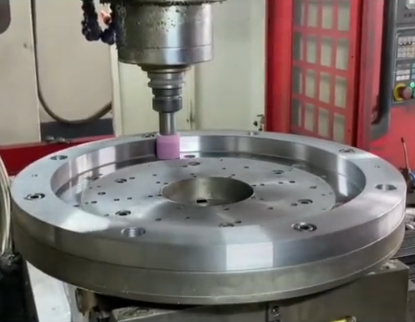
Surface Grinding
Surface grinding processes flat surfaces using a rotating wheel and a reciprocating or rotating worktable.
Main configurations:
• Horizontal spindle, reciprocating table (most common for general flat work)
• Horizontal spindle, rotary table (round workpieces, higher productivity)
• Vertical spindle, rotary table (large surfaces, heavy stock removal)
Surface grinding provides accurate thickness, flatness, and surface finish for plates, blocks, machine components, tool faces, and molds.
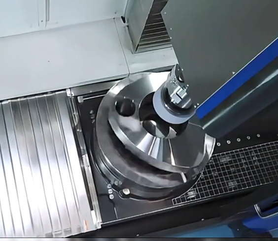
Form and Profile Grinding
Form grinding uses specially dressed wheels or CNC contouring to generate complex profiles. Profile grinding is used for cams, turbine blades, gear teeth, and mold profiles, where contour accuracy and surface integrity are critical.
Tool and Cutter Grinding
Tool grinding machines regrind and manufacture cutting tools such as end mills, drills, reamers, and step tools. CNC tool grinders use multi‑axis interpolation and software libraries for tool geometries. Accuracy of angles, reliefs, and cutting edges is crucial for tool performance.
CNC Grinding Machines and Components
CNC grinding machines combine mechanical rigidity with precise motion control and high‑speed spindles. Understanding their components helps in setup and troubleshooting.
Machine Structure and Axes
The machine base and column provide structural support and vibration damping. Common axes include:
• X‑axis: transverse movement (usually wheel infeed or table cross movement)
• Z‑axis: longitudinal movement (workpiece length direction)
• Y‑axis: vertical movement in some surface and profile grinders
• C‑axis: workpiece rotation (for cylindrical and tool grinding)
• A/B axes: rotary axes for tool grinding and complex profile grinding
Linear guides (box ways or linear rails) and ball screws or linear motors ensure accurate positioning and repeatability.
Spindles
Grinding spindles must provide high rotational speed and low runout to support fine finishes and tight tolerances.
Key parameters:
• Power: from a few kW to tens of kW, depending on wheel size and material removal rate
• Speed range: low for large wheels, high for small wheels
• Bearings: hydrodynamic, hydrostatic, or high‑precision rolling bearings
• Runout: typically in the range of 1–2 μm or better for precision grinding
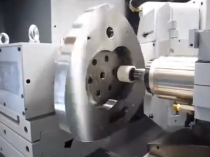
Workholding and Fixtures
Stable workholding is essential for geometry and size control.
Common methods:
• Centers and driving dogs for shaft grinding
• Three‑jaw or four‑jaw chucks for short parts
• Collets for small‑diameter workpieces
• Magnetic chucks for surface grinding plates and blocks
• Custom fixtures and V‑blocks for irregular shapes
Coolant and Filtration Systems
Coolant manages grinding zone temperature, removes swarf, and lubricates the cutting interface.
Key aspects:
• Coolant type: water‑soluble emulsions, synthetic coolants, or straight oils
• Concentration: maintained according to supplier specification
• Delivery: flood, high‑pressure nozzles, or optimized laminar jets at the wheel–work interface
• Filtration: paper band filters, magnetic separators, cartridge or bag filters to remove fine abrasive and metal particles
Abrasive Materials and Grinding Wheel Types
Grinding wheels are engineered tools characterized by abrasive material, grain size, grade, structure, and bond type. Proper selection is critical for productivity and quality.
| Abrasive Type | Typical Materials | Key Characteristics |
|---|---|---|
| Aluminum Oxide (Al2O3) | Carbon steels, alloy steels, tool steels | General purpose, good toughness, widely used |
| White Aluminum Oxide | High‑hardness tool steels, heat‑treated steels | Sharp cutting, cool grinding, friable |
| Silicon Carbide (SiC) | Cast iron, non‑ferrous metals, ceramics, carbides (limited) | Very sharp but brittle, suitable for hard and brittle materials |
| CBN (Cubic Boron Nitride) | Hardened steels (>HRC 55), superalloys | High thermal resistance, long life, high accuracy |
| Diamond | Carbides, ceramics, glass, hard non‑ferrous materials | Hardest abrasive, not recommended for ferrous steels |
Wheel Grade, Grit, and Bond
Important wheel parameters:
• Grit size: smaller numbers (e.g., 24–46) for heavy stock removal; higher numbers (e.g., 80–220) for fine finishes and hard materials.
• Grade (hardness): indicates bond strength holding the grains. Softer grades release dull grains more easily and are suitable for hard materials. Harder grades are used for soft work materials and larger contact areas.
• Structure: spacing between grains. Open structures improve coolant access and chip clearance in heavy grinding; dense structures support fine finishes.
• Bond types: vitrified (ceramic), resin, metal, and hybrid bonds. Vitrified bonds are common in conventional wheels. Resin and metal bonds are used extensively for CBN and diamond wheels.
Wheel Shape and Size
Wheel geometry is matched to machine type and operation:
• Straight wheels for cylindrical and surface grinding
• Cup and dish wheels for tool and cutter grinding
• Form wheels with specific profiles for form grinding
• Small‑diameter wheels for ID grinding and intricate features
CNC Grinding Process Parameters
Controlling the grinding process depends on setting appropriate parameters and monitoring their effect on workpiece quality and tool life.
Wheel Speed and Work Speed
Wheel peripheral speed is a primary parameter. It is determined by wheel diameter and spindle speed:
Typical ranges:
• Conventional wheels: approximately 25–40 m/s
• CBN and diamond wheels: up to approximately 60–160 m/s (depending on wheel design and machine)
Workpiece speed (rotation or table feed) influences surface finish, heat generation, and chip load per abrasive grain. Slower work speeds generally improve surface finish but may increase heat if infeed is too high.
Infeed and Depth of Cut
Grinding infeed is the radial feed of the wheel into the workpiece. It can be specified as:
• Roughing infeed: larger depth for efficient stock removal
• Finishing infeed: very small depth for surface and dimensional accuracy
Typical values (indicative only):
• Rough OD grinding: 0.02–0.08 mm per pass
• Finish OD grinding: 0.002–0.01 mm per pass
• Surface grinding: 0.005–0.03 mm per pass, depending on wheel and material
Feed Rate and Spark‑Out
Feed rate (longitudinal table speed or crossfeed) determines material removal rate and surface finish pattern.
Spark‑out is a period where the wheel traverses without further infeed, allowing elastic deflections to relax and stabilizing size and geometry. Spark‑out time or passes are adjusted according to required tolerance and machine stiffness.
Coolant Flow and Nozzle Position
Coolant parameters to control:
• Coolant flow rate: sufficient to reach the grinding zone and flush swarf
• Nozzle positioning: close to the wheel–work contact point, aligned with wheel speed direction
• Coolant cleanliness: fine filtration to avoid abrasive recutting and wheel glazing
• Temperature control: stable coolant temperature reduces thermal drift and size variation
Programming CNC Grinding Operations
CNC grinding programming defines machine movements, infeed cycles, wheel dressing, and auxiliary functions to execute a repeatable process.
Coordinate Systems and Datum Setting
Programming begins with establishing the work coordinate system (WCS):
• Define zero points in diameter, length, or surface reference
• Measure workpiece location using probes, touch‑off routines, or gauge blocks
• Compensate for wheel wear and dressing offsets using control variables
Canned Cycles and Custom Macros
Many CNC grinders provide built‑in cycles for standard operations:
• Plunge (in‑feed) grinding cycles
• Traverse (through‑feed) grinding cycles
• Multi‑diameter and shoulder grinding cycles
• Taper and radius grinding using interpolation
Custom macros can control complex sequences such as multiple passes with varying infeeds, spark‑out, gauging feedback, and automatic compensation.
Dressing and Truing Programs
Dressing restores the wheel’s cutting ability by removing bond material and dull grains, while truing corrects wheel geometry and runout. Modern machines integrate dressing cycles:
• Rotary diamond dressers for high‑volume operations
• Single‑point or multi‑point diamond tools for conventional wheels
• Roll dressers for complex forms
Dressing parameters (depth, feed, overlap ratio) are programmed to achieve desired wheel sharpness and profile accuracy. Dressing intervals are set by number of parts, cutting time, or monitored by in‑process measurements.
Workpiece Materials and Typical Parameters
Different materials respond differently to grinding. Parameters should be adapted to avoid burn, cracking, or poor surface finish.
| Material | Typical Abrasive | General Approach |
|---|---|---|
| Low/medium carbon steel | Aluminum oxide | Moderate wheel speed, avoid wheel glazing, use appropriate coolant flow |
| Hardened tool steel (>HRC 55) | CBN or white aluminum oxide | Relatively high wheel speed, small infeed, effective cooling to prevent burn |
| Stainless steel | Aluminum oxide (sharp, open structure) | Open wheel structure to reduce loading, steady coolant, moderate infeed |
| Cast iron | Silicon carbide or aluminum oxide | Dry or wet grinding possible, beware of dust, focus on dimensional control |
| Carbide tools | Diamond (resin or metal bond) | High wheel speed, low infeed, careful dressing, stable coolant temperature |
| Nickel‑based superalloys | CBN | High wheel speed with controlled infeed, ample coolant, consistent dressing |
Process Setup, Alignment, and Calibration
Detailed setup ensures that programmed operations translate into reliable production results.
Machine Alignment
Key alignment checks:
• Parallelism between table movement and spindle axis
• Perpendicularity of wheelhead to work table (for surface grinding)
• Alignment of centers for cylindrical grinding
• Runout of workholding devices (chucks, collets)
Alignment is verified using test bars, dial indicators, and precision squares, and is periodically re‑checked in production environments.
Wheel Balancing
Imbalanced wheels cause vibration, poor surface finish, and accelerated spindle wear. Balancing is performed using:
• Static balancing stands with balance weights on the wheel hub
• Dynamic balancing systems mounted on the machine, enabling fine adjustment during operation
Trial Cuts and Parameter Verification
Before serial production, trial grinding is conducted to verify:
• Dimensional accuracy and size approach behavior
• Surface finish level and pattern
• Absence of grinding burn or cracking
• Wheel wear rate and dressing frequency
Adjustments are then made to infeed, feed rate, wheel speed, and dressing parameters to achieve stable, repeatable results.
Quality Control and Inspection Methods
Quality assurance for grinding focuses on geometry, dimensions, and surface integrity.
Dimensional and Geometric Inspection
Common measurements:
• Diameter, thickness, and length with micrometers and calipers
• Roundness, cylindricity, flatness, and straightness using measuring machines or roundness testers
• Taper and runout using dial indicators and reference mandrels
CNC coordinate measuring machines (CMMs) are frequently used for complex profiles, while in‑process gauging can monitor size during grinding for automatic compensation.
Surface Finish and Integrity
Surface finish is evaluated using contact or optical profilometers, typically reported as Ra or Rz values. Requirements can range from Ra < 0.8 μm for general fits to Ra < 0.1 μm for precision components.
Surface integrity inspections may include:
• Visual examination for discoloration and grinding burn
• Nondestructive testing (magnetic particle, dye penetrant) for surface cracks
• Microhardness or metallographic analysis to detect white layer or heat‑affected zones when necessary
Process Stability, Common Issues, and Practical Considerations
Achieving stable CNC grinding requires controlling thermal effects, wheel condition, machine behavior, and workholding.
Thermal Effects and Size Control
Heat generated during grinding can lead to size drift and distortion. Practical controls include:
• Maintaining constant coolant temperature
• Allowing the machine to warm up before fine finishing
• Using spark‑out and light finishing passes to minimize residual stresses
• Planning grinding sequences to reduce localized heating
Wheel Wear, Loading, and Dressing Strategy
Over time, wheels dull, load with swarf, or change profile. Indicators of poor wheel condition:
• Increased grinding forces and machine load
• Deteriorating surface finish
• Onset of chatter marks or vibration patterns
A consistent dressing schedule and optimized dressing parameters keep the wheel sharp, control geometry, and maintain productivity.
Vibration and Chatter
Vibration problems can originate from imbalanced wheels, machine looseness, unsuitable parameters, or workholding stiffness limits. Mitigation steps include:
• Re‑balancing wheels and verifying spindle condition
• Reducing infeed and adjusting feed rates
• Changing wheel grade or structure to a more suitable type
• Improving clamping rigidity and supporting overhanging parts
Workholding‑Related Limitations
Thin‑walled or long, slender parts can deflect under grinding forces, leading to size and geometry errors. Measures to address this include:
• Using steady rests and tailstock support
• Reducing infeed and using multiple light passes
• Employing special fixtures that support deformation‑prone areas
• Sequencing operations to minimize stress buildup
Safety and Environmental Considerations
Grinding operations involve high‑speed wheels, rotating work, and coolant systems. Proper safety measures are mandatory.
Key safety practices:
• Use of appropriate wheel guards and interlocks
• Verification of wheel speed ratings versus machine capability
• Correct mounting and ring testing of wheels before use
• Personal protective equipment: safety glasses, face shields, hearing protection, suitable gloves and clothing when required
Environmental aspects include coolant management, chip and sludge disposal, and air filtration to control mist and dust.
