
Coordinate Measuring Machines (CMMs) are a central tool in dimensional metrology, but they are only one option among several measurement systems used in manufacturing and quality control. Comparing CMMs with optical vision systems, laser scanners, form and surface instruments, gauges, and manual tools across accuracy, speed, and cost helps select the most suitable solution for a specific application.
Overview of Major Industrial Measurement Systems
Dimensional and geometric measurements in industry are carried out using a range of systems, each optimized for certain part sizes, tolerances, and production environments. Understanding the basic working principles and typical use cases is necessary before comparing performance characteristics.
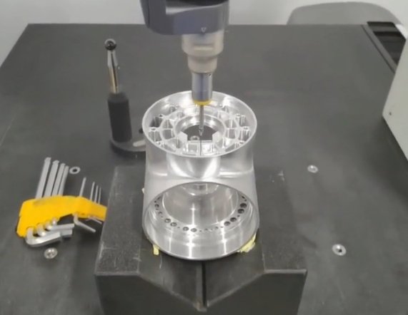
Coordinate Measuring Machines (CMMs)
CMMs determine the coordinates of points on a part surface within a defined measurement volume. They can be equipped with touch-trigger probes, scanning probes, optical probes, and other sensors.
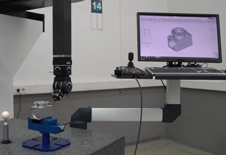
- Bridge CMMs: Common in inspection rooms for medium-sized parts with high accuracy.
- Gantry CMMs: Designed for large and heavy components such as aerospace structures.
- Horizontal-arm CMMs: Often used for automotive body-in-white and large sheet-metal assemblies.
- Portable CMMs: Articulated arms or laser trackers for large parts and shop-floor applications.
CMMs are programmable, can execute complex inspection routines, and are typically integrated with CAD-based measurement software.
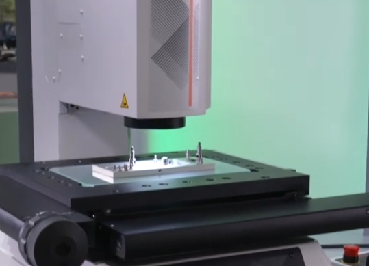
Optical and Vision Measurement Systems
Optical and vision systems rely on cameras, lenses, and lighting, often combined with telecentric optics and image-processing algorithms. They are used for 2D and 2.5D measurements such as lengths, diameters, positions, and edges on parts that are thin, flat, or have well-defined optical contrast.
Variants include:
- 2D vision systems for in-line inspection and presence/absence checks.
- Video measuring machines (VMM) for dimensional metrology with motorized stages.
- Optical comparators and profile projectors for profile and contour evaluation.
Laser Scanners and 3D Scanning Systems
Laser scanners and structured-light systems acquire point clouds from part surfaces rapidly. They are used for full-field dimensional analysis, reverse engineering, and comparison to CAD models. Scanners may be:
- Mounted on CMMs to combine scanning with high-accuracy coordinates.
- Integrated into portable arms for flexible measurement of large parts.
- Handheld or automated in dedicated scanning cells for high-throughput inspection.
Form, Roundness, and Surface Measurement Systems
Specialized instruments are used for rotating and sliding components where form and surface texture are critical. Typical systems include:
Roundness and cylindricity measuring machines with high-precision rotary tables for shafts, bearings, and rings, and surface roughness and contour measuring instruments equipped with stylus sensors to capture fine surface profiles and waviness. These instruments provide high resolution and are focused on a limited set of geometric features.
Gauges and Fixtures
Gauges are commonly used for fast, robust checks in production. Examples are:
Plug and ring gauges for holes and shafts using go/no-go principles, snap gauges, thread gauges, and custom functional gauges built around specific components. Dedicated inspection fixtures with mechanical stops, pins, and dial indicators are also used for repetitive checks of critical dimensions and geometric relations.
Manual Measurement Tools
Manual tools are widely used due to their low cost and simplicity. These include:
Vernier and digital calipers, micrometers, height gauges, dial indicators, and gauge blocks for calibration. They depend strongly on operator skill and are suited to basic dimensions, setup tasks, and low-volume verification.
Accuracy Comparison Across Measurement Systems
Accuracy is a primary criterion when selecting a measurement system. Differences in maximum permissible error, environmental sensitivity, and repeatability must be considered relative to part tolerance and regulatory requirements.
| Measurement System | Typical Maximum Permissible Error (MPE) | Typical Application Tolerance Range |
|---|---|---|
| Bridge CMM (shop-floor grade) | ~(2–5 µm + L/300) | ~±10 µm to ±100 µm |
| Bridge CMM (high-precision) | ~(0.5–2 µm + L/400) | ~±1 µm to ±20 µm |
| Portable CMM arm | ~10–60 µm (depending on size) | ~±50 µm to ±500 µm |
| Laser scanner (on CMM) | ~5–20 µm | ~±20 µm to ±200 µm |
| Handheld 3D scanner | ~20–100 µm | ~±50 µm to ±500 µm |
| Vision measuring system | ~1–5 µm (limited field) to ~10–20 µm (large field) | ~±10 µm to ±100 µm |
| Roundness / form tester | ~0.02–0.1 µm in radius | High-precision form tolerances |
| Surface roughness tester | Sub-micrometre vertical resolution | Ra, Rz etc. in sub-µm to tens of µm |
| Precision micrometer | ~1–3 µm | ~±5 µm to ±50 µm |
| Digital caliper | ~10–30 µm | ~±50 µm to ±200 µm |
| Go/no-go gauges | Pass/fail around nominal with gauge tolerance | Where a functional limit is defined |
L in the table is the measured length in millimetres; typical MPE specifications are expressed as (a + L/b) µm in many manufacturer datasheets. Actual values depend on specific models, configurations, and conditions.
CMM Accuracy Characteristics
CMMs provide multi-axis coordinate measurements with controlled error budgets and traceability. Key technical aspects include:
Granite or ceramic structures and air bearings to minimize friction and thermal expansion, linear scales with resolutions in the sub-micrometre range, volumetric error mapping and compensation across the entire measurement volume, and use of calibration artifacts such as step gauges and ball bars.
Bridge CMMs in temperature-controlled rooms often achieve volumetric length errors around 1–2 µm + L/400. Shop-floor CMMs with enhanced thermal compensation typically exhibit slightly higher MPE values but allow measurement closer to production lines. Repeatability is often below 1 µm for short-range measurements, making CMMs suitable for tight tolerances and detailed geometric dimensioning and tolerancing (GD&T) analysis.
Accuracy of Vision and Optical Systems
Vision systems can achieve very high accuracy over small fields of view, particularly with telecentric optics, high-resolution sensors, and stable lighting. Accuracy is influenced by pixel size, magnification, lens distortion, focus, and illumination uniformity.
For small parts such as connectors, electronic components, or stamped parts, video measuring machines can achieve measurement errors in the low micrometre range. However, as the measurement field increases, errors accumulate, and volumetric accuracy over large 3D envelopes is generally lower than that of a high-grade CMM. Vision systems are also more sensitive to surface finish, reflectivity, and color contrasts, which may limit their use on some materials without surface preparation.
Accuracy of Laser Scanners and 3D Scanning Systems
Laser and structured-light scanners capture large point clouds quickly but generally do not match the point accuracy of high-end CMM probing. Factors affecting scanner accuracy are triangulation geometry, calibration of cameras and projectors, incidence angle and surface reflectivity, ambient light, and distance to the part.
When mounted on a CMM, scanners can combine the CMM’s precise coordinate frame with dense point coverage, improving global dimensional integrity compared to handheld use. Handheld scanners are more susceptible to operator motion, alignment errors, and drift, leading to larger uncertainty in absolute dimensions, though local feature comparisons and shape verification are often sufficient for many applications.
Accuracy of Gauges and Manual Tools
Gauges offer consistent pass/fail decisions when designed and maintained properly. Their accuracy is embedded in the gauge manufacturing tolerance and calibration. They do not provide actual measurement values but ensure that a dimension is within defined limits.
Micrometers and calipers are limited by instrument resolution, flatness and parallelism of contact faces, measuring force, and operator technique. They are effective for simple dimensions but cannot reliably assess complex GD&T requirements such as true position in 3D, complex profiles, or combined tolerances on multiple features.
Measurement Speed and Throughput Considerations
Measurement speed influences inspection coverage, sampling strategies, and integration with production. Different systems achieve speed through automation, parallel measurement, or simplified evaluation.
CMM Measurement Speed
CMM speed is defined by probing strategy, traverse speeds, probe type, and part complexity. Typical factors include:
Point-to-point touch-trigger probing, which takes a finite time per point due to machine movement, probing event, and data processing, scanning probes that collect continuous data along paths and can capture hundreds or thousands of points per second, modern CMM drives with high acceleration and velocity parameters, and optimized probing routines that reduce non-productive moves.
Despite these improvements, complex 3D inspections with many features can still require minutes to over an hour per part, depending on feature count and part size. CMMs are therefore often used for first-article inspection, process capability studies, and periodic sampling rather than 100% inspection of high-volume production when cycle time is critical.
Speed of Optical and Vision Systems
Vision systems excel at speed, especially when many features lie in a single field of view. With a single image acquisition, multiple dimensions such as lengths, hole positions, and edge locations can be extracted simultaneously through image-processing algorithms.
In automated lines, cameras can inspect parts in fractions of a second, supporting 100% inspection for high-volume processes like electronics assembly, packaging, or small precision components. For multi-step video measuring machines, speed is still high compared with manual probing due to motorized stages, programmable zoom, and automatic feature recognition. However, parts requiring multiple reorientations or 3D coverage can increase cycle time.
Speed of Laser Scanners and 3D Scanning
Laser scanners and structured-light systems provide high-speed area acquisition. Instead of discrete points, they acquire point clouds or meshes for entire surfaces in seconds. This is advantageous for large, freeform parts such as castings, plastic components, and sheet-metal panels.
The overall inspection time includes scanner setup, surface preparation if required, scanning passes, data alignment, and analysis. Automated scanning cells with robots can reduce operator time significantly and maintain consistent scanning paths. When combined with streamlined analysis routines, scanning-based inspection can evaluate many dimensions in less time than a point-wise CMM program for the same part.
Speed of Gauges and Manual Methods
Go/no-go gauges and dedicated fixtures are among the fastest methods for routine checks. Operators can verify critical dimensions or features in seconds. This supports immediate feedback during machining or assembly and allows frequent checking without bottlenecks.
Manual tools such as calipers and micrometers are relatively fast for small numbers of dimensions but do not scale well to parts with many critical features. As the number of measurements per part increases, cycle time grows rapidly and is strongly influenced by operator skill and fatigue.
Cost Analysis: Equipment, Operation, and Lifecycle
Cost evaluation should consider acquisition cost, integration, operational expenses, training, maintenance, and indirect costs such as scrap reduction and process control. The relationship between accuracy, speed, and cost is central to system selection.
| System Type | Typical Initial Investment | Relative Operating Cost | Typical Use |
|---|---|---|---|
| Bridge CMM | Medium to high | Medium | High-accuracy, multi-feature inspection |
| Shop-floor CMM | Medium to high | Medium | Near-line dimensional control |
| Portable CMM arm | Medium | Medium | Large parts, flexible inspection |
| Vision measuring system | Medium | Low to medium | Fast, precise 2D/2.5D measurements |
| Laser / 3D scanner | Medium to high | Medium | Full-surface inspection, reverse engineering |
| Roundness / surface instruments | Medium | Low | Specialized form and roughness checks |
| Dedicated gauges / fixtures | Low to medium (per gauge; can be high in total) | Low | High-volume pass/fail checking |
| Manual tools | Low | Low | Basic dimensions, setup, small series |
Actual numerical costs depend on measurement range, configuration, automation level, and vendor; the table shows relative levels for comparison purposes.
Initial Investment for CMMs
CMMs typically require a significant capital investment. Factors influencing purchase cost are measurement volume, accuracy specification, choice of probes and probe changers, environmental enclosures or shop-floor housings, software options for GD&T, scanning, and reporting, and integration with conveyors, pallets, or robots.
Bridge CMMs with moderate volumes and standard probes represent a common balance between capability and budget. Larger gantry systems, horizontal-arm machines, and multi-sensor configurations increase cost but may be justified by part size, accuracy needs, or measurement complexity.
Operating and Maintenance Costs
Operating costs for CMMs and other systems include calibration and verification at defined intervals, preventive maintenance and repairs, software maintenance contracts and updates, operator and programmer training, and fixture design and manufacturing for part positioning.
CMMs often require specialized programming skills, especially for complex parts with extensive GD&T. This programming effort forms a significant portion of lifetime costs but can be amortized over high part counts or long product lifecycles. Vision systems and gauges may have lower programming or configuration requirements for simple parts but can become complex for multi-variant products.
Cost of Vision, Scanning, and Gauging Solutions
Vision systems generally offer lower volumetric accuracy than high-end CMMs but can be more economical in high-volume applications due to faster cycle times and simpler operation. Costs depend on camera resolution, optics, motion stages, lighting, and automation.
3D scanning systems range from portable handheld scanners to fully automated cells. Costs scale with accuracy, field of view, automation, and data processing software. Although initial investment can be comparable to a CMM, the ability to inspect many features simultaneously may reduce overall inspection cost per part in suitable applications.
Dedicated gauges and fixtures have relatively low unit costs but can accumulate considerable expenses when many product variants or revisions exist. Gauge maintenance, storage, and recalibration also contribute to lifecycle costs.
Indirect Cost and Risk Considerations
Indirect costs and risk mitigation also influence system selection. Inadequate measurement capability can lead to acceptance of non-conforming parts, field failures, warranty claims, or regulatory non-compliance. Overly slow inspection can delay production or reduce sampling frequency, increasing the risk of undetected process drift.
CMMs, with their flexibility and traceability, reduce risk when dealing with complex, high-value components such as engine parts, medical implants, or aerospace structures. They allow comprehensive measurement and data retention, supporting root-cause analysis and long-term quality records.
Application Scenarios Where CMMs Excel
CMMs are not always the fastest or lowest-cost option, but they are often the most appropriate when flexibility, traceability, and multi-dimensional accuracy are required.
Complex Geometries and GD&T Requirements
CMMs are designed for complex geometries and full 3D GD&T evaluation, including features such as true position of hole patterns referenced to datums, profile tolerances of freeform surfaces relative to CAD models, geometric relations across distant features within the same coordinate system, and combined tolerances involving multiple datums and modifiers.
Probing strategies can adapt to different surface types, from prismatic features to turbine blades or orthopedic components. CMM software typically includes advanced algorithms for alignment, best-fit, and GD&T evaluation in accordance with standards.
Flexible, Multi-Part and Multi-Variant Inspection
When a facility produces many different part numbers or frequently changes designs, CMM flexibility becomes valuable. A single CMM can measure a large variety of parts by switching programs and probes instead of requiring new gauges or fixtures for each variant.
This reduces the need for physical tooling and shortens the response time to design changes. Parametric and CAD-driven measurement programs can be reused with modifications, further improving adaptability.
High Accuracy and Calibration Roles
High-precision CMMs often serve as reference instruments for internal calibration and verification. They can be used to:
Verify the dimensions of gauges and fixtures, support capability studies (such as repeatability and reproducibility evaluations) of other measurement systems, and provide reference data for process capability indices. In metrology laboratories, CMMs operate as a central reference in the measurement traceability chain for complex geometries and coordinates.
Traceability and Documentation
CMMs automatically record measurement results, including point coordinates, alignments, and GD&T evaluations. This data can be stored, analyzed, and linked to specific parts, batches, or serial numbers. Automated report generation supports quality documentation, compliance with standards, and communication with customers.
For industries that require comprehensive documentation and traceability, such as aerospace and medical, the structured data from CMMs is often a key element of quality management systems.
Situations Where Other Systems Are Preferable
Although CMMs are versatile, other systems may be better suited in terms of speed, integration, or cost for certain tasks.
High-Volume, Repetitive Production Checks
In environments where a small number of dimensions must be checked on every part at high throughput, dedicated gauges or inline vision systems are often more appropriate than a CMM. Examples include checking a single bore diameter, verifying overall height of a component, ensuring presence and position of features in assembly operations, and pass/fail verification of threads or simple fits.
These solutions minimize cycle time and operator intervention and can be directly integrated into production lines.
Fine Features, 2D Profiles, and Small Components
Small components such as stamped parts, connectors, springs, and micro-mechanical elements often benefit from optical or vision measurement. Vision systems can measure fine features without contact, avoiding deformation on delicate parts, and capture entire 2D profiles and edge positions in a single image.
For contour and profile measurements requiring very high resolution on small areas, optical comparators, profile projectors, and video measuring machines can be more efficient and equally or more accurate locally than a CMM, especially when many features lie within a small field.
Freeform Surfaces and Full-Field Comparison
When the goal is to evaluate full freeform surfaces rather than a limited set of discrete features, laser and structured-light scanners offer substantial advantages. They provide dense point clouds suitable for color-map deviation plots against CAD, surface reconstruction for reverse engineering, and shape analysis of complex molded or cast parts.
While a CMM can sample key points on a freeform surface, achieving full coverage point-by-point would be slow. Scanners obtain a more complete surface representation in shorter time, though with generally higher measurement uncertainty per point compared to high-end probing.
Large Structures and In-Situ Measurements
Large assemblies such as machine tools, ship sections, building components, and large welded frames often cannot be brought to a CMM. Portable CMM arms, laser trackers, and photogrammetry systems enable on-site measurement of large structures and alignment tasks.
These systems trade some accuracy for measurement range and portability but are adequate for many large-scale tolerances and installation requirements.
Limitations of CMMs
While CMMs are powerful, their use may introduce practical difficulties in some environments or applications.
Environmental and Infrastructure Requirements
High-accuracy CMMs typically operate best in controlled environments with stable temperature and limited vibration. Requirements include dedicated rooms or enclosures with temperature stability around the specified range, vibration isolation measures depending on foundation and surroundings, controlled air cleanliness to protect bearings and scales, and stable power and compressed air supply for air bearings.
Meeting these conditions may require capital investment in infrastructure and can limit machine placement close to the production line. Shop-floor CMMs mitigate some of these issues but still require appropriate environmental management.
Programming Complexity and Skill Requirements
Programming complex CMM inspections demands understanding of metrology principles, GD&T, coordinate systems, probing strategies, and software operation. This can create bottlenecks when new parts are introduced frequently or when experienced programmers are limited.
Training time for new users and the need to maintain programming standards across teams must be considered. Although modern software provides CAD-based programming and libraries of standard routines, complex parts still require careful planning and validation of programs.
Measurement Cycle Time for Complex Parts
For parts with numerous features and tight tolerances, CMM measurement times may be substantial. This can affect throughput, especially when measurement is part of process control loops that require timely feedback.
Strategies to reduce cycle time include optimizing probe paths and measurement strategies, using scanning instead of single-point probing where appropriate, balancing the depth of inspection with statistical sampling strategies, and combining CMM inspection with faster in-line checks for selected features. Nevertheless, for very high production volumes, CMMs are often used for sampling and capability studies rather than full inspection of every part.
Workholding and Part Preparation
To achieve the specified accuracy, parts must be properly fixtured and aligned. Designing and manufacturing fixtures, or configuring modular fixturing systems, adds time and cost. Improper fixturing can lead to measurement errors from part deformation, movement during probing, or misalignment.
Parts with complex shapes or soft materials can be challenging to fixture without introducing measurement bias. Reducing clamping forces, using supportive fixtures, and validating setups with repeatability studies are essential but require additional effort.
Key Technical Selection Criteria
Selecting between a CMM and other measurement systems requires a structured evaluation of technical and economic factors. Considering the interplay of accuracy, speed, and cost in the context of specific applications prevents over- or under-specification.
1) Tolerance and Accuracy Requirements
The tightest tolerances and GD&T requirements define the minimum necessary accuracy and uncertainty of the measurement system. Important considerations are linear dimensions, angular tolerances, form and location tolerances, surface roughness specifications, and regulatory or customer requirements for traceability and uncertainty budgets.
If the required measurement uncertainty is a small fraction of the tolerance (for example, 10–25%), a high-precision CMM or specialized form instrument may be suitable. For looser tolerances, less precise but faster or cheaper systems might be adequate.
2) Part Size, Geometry, and Material
Part characteristics influence the feasible measurement methods. Large components may require gantry CMMs, horizontal-arm CMMs, portable arms, or trackers. Small, flat, or transparent parts may be better suited to vision systems. Soft, delicate, or flexible materials may demand non-contact methods to avoid deformation, while highly reflecting or transparent surfaces may require surface treatment for optical systems.
Geometric complexity, such as freeform surfaces and internal features, determines the need for multi-axis probing, scanning, or specialized sensors.
3) Production Volume and Inspection Strategy
Production volume shapes the balance between flexible, programmable systems and dedicated, high-throughput devices. For low to medium volume and high product variety, flexible systems such as CMMs, video measuring machines, and portable scanners are usually more economical. For high-volume production of stable designs, dedicated gauges and inline vision systems often provide the best cost per part.
The sampling strategy, whether 100% inspection, statistical sampling, or first-article and periodic checks, also influences system choice. CMMs are often central to first-article inspection and capability studies, while faster systems may handle routine checks.
4) Integration, Data Use, and Automation
Measurement data increasingly feeds back into manufacturing systems for process control, traceability, and optimization. Key integration aspects include compatibility with CAD and PLM systems for CAD-based programming and analysis, data exchange formats and connectivity to quality systems, MES, or ERP, and automation interfaces for robotic loading, conveyors, and pallet systems.
CMMs usually feature advanced data handling and reporting capabilities, making them suitable where measurement results are heavily used for analysis, reporting, or closed-loop control. Simpler systems may provide limited data but are sufficient when pass/fail decisions or a few key dimensions are needed.

Practical Guidelines for Choosing Between CMM and Alternatives
In practice, many facilities deploy multiple measurement systems, with CMMs forming part of an integrated metrology strategy. A practical approach to selection includes the following considerations.
Typical Situations Favoring CMMs
CMMs are commonly the preferred choice when a wide range of dimensions and GD&T callouts must be verified on complex parts, accuracy requirements are tight relative to tolerances, and traceable, documented data is required for regulatory or customer reasons. They also serve effectively as reference instruments for calibration of gauges and verification of other measurement systems.
Typical Situations Favoring Other Systems
Alternative systems may be more appropriate when only a few critical dimensions need fast checking on every part, in-line or near-line where measurement must not slow production, for small, flat, or highly repetitive parts where vision and optical systems offer high throughput, and for freeform surfaces where full-field 3D scanning supports comprehensive shape analysis in shorter time than a point-based CMM program.
Combining Systems for Complementary Strengths
A combined approach often yields the best performance. For example, CMMs can perform detailed first-article inspection, capability studies, and periodic audits; scanners can provide rapid surface coverage and visual deviation maps; and gauges and vision systems can handle high-volume, repetitive checks of a few key features.
By distributing tasks according to strengths, it is possible to maintain overall quality control with acceptable cost and throughput, while reserving CMM capacity for measurements that genuinely require its capabilities.
FAQ
How does a CMM compare to optical measurement systems?
CMMs provide extremely high accuracy and repeatability through tactile probing, while optical systems offer faster data capture for complex surfaces but may be more sensitive to lighting and surface finish.
What is the difference between a CMM and laser scanning systems?
CMMs measure discrete points with high precision, whereas laser scanners capture dense point clouds quickly, making scanners better suited for freeform or reverse engineering applications.
When should a CMM be used instead of manual measurement tools?
A CMM should be used when high precision, repeatability, and automated inspection are required, especially for complex geometries that cannot be reliably measured with calipers or micrometers.
Are CMMs more accurate than vision measurement systems?
In most cases, CMMs offer higher dimensional accuracy than vision systems, particularly for critical tolerances, while vision systems excel in speed and non-contact measurement.
Is a CMM always the most accurate measurement system?
A high-grade CMM offers excellent volumetric accuracy across a 3D measurement volume, making it suitable for many tight-tolerance applications. However, specialized instruments such as roundness testers and surface roughness systems can achieve higher local accuracy for their specific functions, and vision systems can be very accurate over small fields. The most accurate system depends on the geometry and type of measurement.
