
CMM (Coordinate Measuring Machine) inspection is a central element of dimensional quality control in precision manufacturing. A structured, repeatable workflow ensures that critical dimensions and geometric tolerances are verified with high accuracy and traceability. This article presents a systematic, technically detailed view of the complete CMM inspection workflow, from requirement analysis to data feedback into production.
Role of CMM Inspection in Precision Manufacturing
CMM inspection provides quantitative, traceable dimensional data that links engineering design, manufacturing processes, and quality assurance. In high-precision environments such as aerospace, automotive, medical devices, and mold making, CMMs verify features that are difficult or impossible to measure reliably with conventional gauges.
Typical roles of CMM inspection include:
- Verification of critical dimensions and GD&T features against engineering drawings or 3D CAD models
- First article inspection (FAI) for new parts or new processes
- In-process and final inspection to control production stability
- Measurement-based process capability assessment (Cp, Cpk)
- Reverse engineering support through point cloud capture and feature reconstruction
By standardizing the workflow, manufacturers ensure consistent measurement results independent of operator, shift, or production batch, while aligning inspection activities with customer and regulatory requirements.
Types of CMMs and Their Application Context
The CMM inspection workflow depends in part on the type of CMM, its sensor system, and its integration into production. Understanding these fundamentals supports appropriate workflow design and parameter selection.
| CMM Type | Characteristics | Typical Use Cases |
|---|---|---|
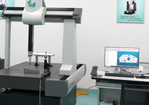
| Bridge CMM | High accuracy, stable granite base, moderate measuring volume | Precision components, gauges, mold inserts, small to medium prismatic parts |
| Gantry CMM | Large measuring volume, high rigidity, floor-mounted | Automotive body-in-white, large aerospace structures, heavy components |
| Horizontal Arm CMM | Wide reach, accessibility from the side, suitable for sheet metal | Car bodies, large plastic components, dies, fixtures |
| Shop Floor CMM | Thermally compensated, robust, close to production machines | In-line or near-line inspection, process control, shorter feedback loops |
Sensor technologies commonly used:
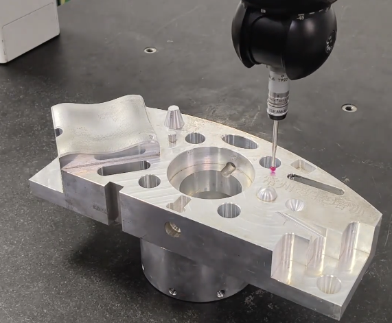
- Touch-trigger probes (e.g., 5-way or 6-way probes) for discrete point measurements
- Analog scanning probes for continuous surface and form measurement
- Optical and laser sensors for non-contact measurement of delicate or soft parts
For each CMM and sensor configuration, the workflow must consider measurement accuracy (MPE values), repeatability, probing speed, and environmental conditions.
Pre-Inspection Requirement Analysis
The workflow begins with a structured analysis of what must be measured and why. This step aligns design intent with inspection strategy.
Review of Design Data and Specifications
Key inputs include:
- 2D drawings with GD&T callouts: dimensions, tolerances, datum structure
- 3D CAD models: nominal geometry, surface definitions, toleranced features
- Technical product documentation: material, heat treatment, finishing
Inspection planning focuses on:
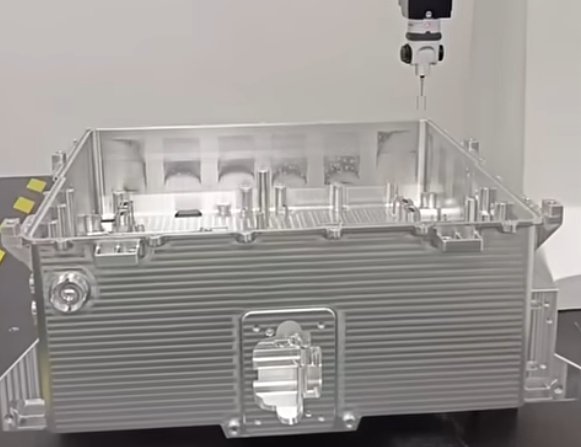
Critical characteristics: Features with small tolerances or high functional importance, such as mating surfaces, sealing areas, bearing bores, gear tooth geometry, and alignment features. These often demand tighter control of measurement uncertainty.
Typical parameters derived from design data:
- Dimensional tolerances (e.g., ±0.005 mm, ±0.010 mm)
- Geometric tolerances per ISO 1101 / ASME Y14.5 (position, flatness, cylindricity, profile)
- Datum reference frames and measurement directions
- Surface requirements influencing probing (roughness, coatings)
Definition of Inspection Scope and Acceptance Criteria
The inspection scope depends on customer requirements, internal quality plans, and process capability. Define:
- Which features are measured 100% and which are sampled
- Required statistical measures (e.g., X̄, σ, Cp, Cpk, Pp, Ppk)
- Pass/fail thresholds and any boundary conditions (e.g., sorted classes)
In aerospace or medical industries, inspection often includes complete dimensional verification of safety-critical components. In automotive mass production, a combination of 100% checks for a few key characteristics and sampling for others is typical.
Fixture Design and Workpiece Setup
Stable and reproducible workholding is fundamental to reliable CMM inspection. Part setup must ensure that measurement data reflect part geometry and not positioning errors or deformation.
Workholding Principles
Effective fixture design respects the following principles:
- Define a stable 3-2-1 location: three points for primary support, two for secondary, one for tertiary, constraining all six degrees of freedom
- Avoid over-constraining the part, which can introduce internal stress and deformation
- Provide sufficient clamping force for stability without distorting thin-walled or flexible parts
- Ensure accessibility of all features to be measured, minimizing probe collisions and excessive head rotations
Materials for fixtures are usually chosen for stiffness, dimensional stability, and compatibility with part material. Aluminum, steel, and modular fixturing systems are common. For optical sensors, low-reflection and low-scatter materials are preferred.
Alignment to Machine Coordinate System
Once the part is mounted, the part coordinate system must be established on the CMM. This involves:
- Choosing alignment features consistent with drawing datums (planes, cylinders, holes, slots)
- Measuring these features to construct a datum reference frame
- Defining orientation (rotations) and location (translations) relative to the CMM coordinate system
Typical alignment sequence:
- Level the part by referencing a planar surface to define Z orientation
- Align the part rotation in the XY plane using a linear feature or pattern
- Set the origin (0,0,0) at a defined intersection of datums or a feature center
This alignment procedure is often embedded in an automated program with initial manual probing for the first part and subsequent automatic execution for repeated measurements.
Probe System Selection and Qualification
Proper selection and qualification of the probe system ensure that measurement uncertainty remains within acceptable limits for the required tolerances.
Probe Type and Stylus Configuration
Factors influencing probe configuration include feature size, accessibility, surface condition, and required measurement speed. Typical stylus parameters:
- Ball diameter: often ranging from 1 mm to 10 mm for general tasks, smaller diameters for fine features such as small bores or grooves
- Stylus length: balanced between reach requirements and stiffness; longer styli increase bending and uncertainty
- Material: carbide, ceramic, or carbon fiber stems; ruby, silicon nitride, or other ball materials
Touch-trigger probes are suitable for discrete point acquisition of prismatic features. Analog scanning probes are preferred for capturing form, profile, and high point-density data on complex surfaces.
Probe Calibration and Qualification
Before measurement, the CMM must know the exact probe tip geometry and orientation. Standard steps:
- Probe qualification on a reference sphere of known diameter and position
- Establishment of probe offsets for different tip directions and stylus modules
- Verification of probe repeatability and lobing using multiple approaches to the reference sphere
Qualification involves:
- Number of qualification points: typically 5 to 25 points distributed around the sphere
- Approach speed and probing force appropriate to stylus stiffness and ball size
- Environmental stability during qualification (temperature close to CMM calibration conditions)
Probe calibration results are stored in the CMM software and linked to specific probe configurations. Switching configurations during inspection requires automatic recognition and usage of the corresponding calibration data.
Measurement Strategy and Feature Selection
A measurement strategy defines how the CMM acquires data from each feature to achieve the required accuracy and repeatability within acceptable cycle time.
Feature Measurement Approaches
Common strategies for individual features include:
- Planes: distributed points (e.g., 4–10 points) away from edges and damaged zones
- Holes and cylinders: multiple points in one or several cross-sections; scanning for form analysis if needed
- Slots: measurement of opposing faces and evaluation of center plane and width
- Cones: point or scanning measurement along the generatrix for angle and axis position
- Freeform surfaces: continuous scanning paths, often guided by CAD models
Point density and distribution are crucial. Increasing the number of points reduces statistical uncertainty of feature fitting but lengthens cycle time. For tight tolerances or form control, scanning strategies with controlled speed and point spacing are preferred.
GD&T-Oriented Strategy
When inspecting GD&T features, the strategy must reflect the underlying datums and feature control frames. Examples:
- Position: measure the feature (e.g., hole) and all referenced datums, simulate material boundaries if required
- Flatness: capture sufficient points or scans across the surface to detect local deviations
- Cylindricity: use full 3D scanning around the cylinder to resolve form deviations along length and circumference
- Profile: follow defined CAD curves or surfaces, controlling normal vectors and point spacing
Measurement directions relative to datums are important for separating out-of-flatness, tilt, and translation effects. The use of proper fit algorithms (e.g., least-squares, minimum circumscribed, maximum inscribed, or tangential conditions) must be consistent with drawing standards and function.
Programming the CMM Inspection Routine
Modern CMM inspection relies on offline or online programming to create repeatable, automated routines. These programs govern probe paths, measurement sequences, and evaluation rules.
Program Creation and Structure
Key elements in a typical CMM program:
- Initialization: loading of CAD model, probe configuration, environmental compensation parameters
- Alignment routine: probing of datum features and establishment of the part coordinate system
- Feature measurement routines: measurement paths and parameters for each feature
- GD&T evaluation: calculation of tolerance values, deviation vectors, and pass/fail status
- Reporting: formatted results, graphs, and statistics
Offline programming uses CAD models and virtual CMM environments to simulate movements and avoid collisions before running on the physical machine. This reduces machine downtime and accelerates program development.
Path Planning and Collision Avoidance
Path planning aims to minimize travel distance and measurement time while respecting:
- Safe approach distances to avoid collisions with fixtures or part geometry
- Clearance planes and retract distances for probe repositioning
- Rotational limitations and acceleration of motorized probe heads
Common parameters:
- Approach distance: often 2–5 mm from the surface before probing
- Retraction distance: similar or larger than approach distance for safe movement
- Probing speed: chosen to balance cycle time and probing dynamics, typically lower for high precision or fragile styli
Collision detection functions in the software use CAD models of the part, fixture, CMM, and probe system to ensure that programmed paths are feasible. Any issues identified in simulation are corrected before running the program on real parts.
Executing the Measurement Cycle
Once the program is ready and verified, it is executed for actual parts. Execution includes operational checks, part loading, and monitoring of environmental conditions.
Part Loading and Identification
The operator performs standardized steps for each measurement cycle:
- Cleaning the part and fixtures to remove chips, coolant, oil, or dust
- Mounting the part in the fixture using predefined clamping points
- Verifying correct fixture configuration and probe setup
- Identifying the part (e.g., barcode, serial number, batch) for traceability
If the workflow requires, the CMM software may prompt for part data or automatically read identifiers. This information is stored with the measurement results.
Measurement Execution and Monitoring
During routine execution:
- The program performs alignment probing; if alignment fails thresholds, the cycle can be aborted or flagged
- The CMM measures all programmed features, storing raw points and calculated results
- Any collisions or probe errors trigger predefined responses (pause, stop, or controlled recovery)
The operator monitors basic parameters such as machine status and ambient conditions. CMMs located in controlled rooms typically operate near 20 °C with limited temperature gradients, while shop-floor CMMs may apply real-time temperature compensation based on machine and part sensors.
Data Processing and GD&T Evaluation
After the measurement cycle, the CMM software processes the collected points, fits geometrical features, and evaluates them against tolerances and GD&T requirements.
Feature Fitting and Filtering
Data processing steps include:
- Compensation of probe radius based on contact direction and stylus geometry
- Fitting of geometrical elements (planes, lines, circles, cylinders, cones, spheres) using algorithms such as least-squares or Chebyshev
- Filtering of high-frequency noise when evaluating surface form, within the limits of applicable standards
The choice of fitting algorithm influences the derived feature parameters. For example, minimum circumscribed circles are suitable for certain gauge fits, while least-squares circles are often used for functional dimensions. Consistency with drawing conventions and customer requirements is essential.
GD&T Calculation and Result Interpretation
For GD&T features, the software calculates:
- Deviations of measured features from nominal in X, Y, Z and orientation
- Tolerance values such as flatness, straightness, circularity, cylindricity, position, profile, and runout
- Datum simulations and virtual condition boundaries if applicable
Results are compared to specified tolerances, and a pass/fail status is assigned to each feature. Detailed deviation maps or color-coded plots may be generated for complex surfaces, showing local deviations relative to nominal surfaces.
Reporting, Documentation, and Traceability
Inspection reports translate measurement data into a format that can be used by engineers, quality personnel, and customers. Transparent reporting supports traceability, regulatory compliance, and problem-solving.
Report Content and Structure
Typical report components:
- Part identification: part number, revision, serial/batch number
- Inspection information: date, time, inspector, CMM identification, software version
- Environmental conditions: temperature, humidity (when required)
- Measurement results: numerical values, nominal values, tolerances, deviations, pass/fail status
- GD&T results: values for each feature control frame, graphical representations if necessary
Reports can be generated in various formats, such as PDF, CSV, or database entries. In many workflows, results are automatically transferred to quality management systems, ERP systems, or SPC software.
Record Retention and Audit Support
For industries with stringent documentation requirements, the CMM workflow includes structured record retention:
- Storage of raw point data, processed features, and aligned coordinate frames
- Retention of inspection programs with version control and change history
- Archived calibration certificates for CMM and probes
- Signed or electronically authenticated reports for audits
These records provide evidence that parts have been measured in accordance with documented procedures and that measurement equipment is maintained within calibration status.
Integration with Process Control and SPC
CMM inspection data become more valuable when they are systematically used to control and optimize the manufacturing process. The workflow should include defined channels for feedback to production and engineering.
Statistical Analysis and Capability Assessment
For repeated measurements of the same feature across a batch or over time, the following indices are commonly used:
- Cp and Cpk: process capability based on within-subgroup variation
- Pp and Ppk: long-term performance indices based on overall variation
- Control charts (X̄-R, X̄-S charts) for monitoring central tendency and dispersion
By analyzing trends and variations, engineers can determine whether the process is capable of maintaining parts within tolerances with sufficient margin. CMM results thus support decisions on machine adjustments, tool changes, and process optimization.
Feedback Loop to Manufacturing
A closed workflow links inspection to manufacturing decisions:
- Deviation patterns indicate specific process issues (e.g., misalignment, tool wear, thermal drift)
- Out-of-tolerance features trigger corrective actions such as machine recalibration or modification of machining parameters
- Updated machining offsets based on CMM measurements improve centering within tolerance zones
In some environments, CMMs are directly integrated into production control systems, enabling automatic adjustment of machine tools based on measurement results. Even without full automation, timely manual feedback based on CMM reports improves dimensional stability and reduces scrap and rework.
Measurement Uncertainty and Validation
Understanding and controlling measurement uncertainty is essential to ensuring that inspection results are reliable for decision-making in precision manufacturing.
Contributors to Measurement Uncertainty
Main contributors include:
- CMM geometry and calibration status (MPE values per ISO 10360 or comparable standards)
- Probe system characteristics: stylus stiffness, ball diameter, probing force, trigger repeatability
- Environmental conditions: temperature, gradients, vibrations, air flow
- Part properties: material, thermal expansion, flexibility, residual stresses
- Measurement strategy: number and distribution of points, scanning speed, alignment choices
For high-precision features, the workflow often includes an uncertainty budget or at least a justified estimate of measurement uncertainty, ensuring that it remains significantly smaller than the specified tolerance.
Verification and Correlation
Validation of the CMM workflow involves:
- Regular calibration and verification of the CMM using traceable artifacts (step gauges, ball plates, length standards)
- Gauge R&R studies to evaluate repeatability and reproducibility of the CMM inspection process
- Correlation with alternative measurement methods (e.g., air gauges, micrometers, optical systems) when appropriate
Documented verification supports confidence in CMM results and demonstrates compliance with internal and external quality requirements.
Workflow Optimization and Standardization
Once a reliable CMM workflow is established, systematic optimization and standardization can reduce inspection time, improve comparability of results, and facilitate training.
Standard Operating Procedures (SOPs)
SOPs describe each step of the workflow, including:
- Fixture setup and clamping sequences
- Probe configuration selection and qualification intervals
- Measurement program selection and parameter settings
- Criteria for accepting or rejecting measurement cycles
- Steps for handling non-conforming parts and measurement anomalies
By using standardized documentation, operators follow consistent practices, reducing variation due to human factors and ensuring that inspections are performed in a reproducible manner.
Cycle Time and Resource Planning
Inspection cycle time influences production throughput and resource allocation. Optimization may include:
- Grouping features in logical sequences to minimize probe head rotations and long travels
- Adjusting point densities where appropriate, without compromising risk of missing critical deviations
- Parallelizing tasks such as part loading and program preparation
CMM capacity planning considers part mix, inspection frequency, and required response times. Balanced workflows reduce bottlenecks in the quality department and ensure that measurement results are available when needed for production decisions.
Typical Practical Issues in CMM Inspection
In real production environments, several practical issues can affect CMM inspection workflows. Addressing them systematically improves reliability and throughput.
Surface Condition and Probing Quality
Surface condition can influence contact detection, especially for small stylus balls and low probing forces. Examples:
- Residual burrs or machining marks leading to overestimation of measured size or form deviations
- Contaminants such as oil or dust causing unstable triggering or poor repeatability
- Highly reflective or porous surfaces affecting optical sensors
Standard cleaning procedures and, where necessary, dedicated pre-inspection treatments are incorporated into the workflow to minimize these effects.
Flexible and Thin-Walled Components
Thin-walled parts and flexible components present specific difficulties:
- Deformation under clamping or gravity can alter measured dimensions
- Probing forces can locally distort the part during measurement
- Repeated probing of sensitive areas may gradually change geometry
Mitigation measures include optimized fixturing, minimized probing forces, and selection of measurement strategies that support the part in a way representative of its function in assembly.
Example of a Structured CMM Inspection Workflow
The following table summarizes a generic, structured CMM inspection workflow for precision manufacturing. It illustrates how individual steps combine into a coherent process.
| Workflow Step | Main Activities | Key Outputs |
|---|---|---|
| Requirement Analysis | Review drawings, GD&T, CAD; define critical characteristics | Inspection plan, feature list, acceptance criteria |
| Fixture and Alignment Design | Design workholding, define datum strategies, verify accessibility | Fixture concept, alignment scheme, setup instructions |
| Probe Selection and Qualification | Select probe and stylus configuration; calibrate probes; verify repeatability | Validated probe configurations with calibration data |
| Measurement Strategy | Define point densities, scanning paths, feature-specific approaches | Documented strategy linked to inspection plan |
| Program Development | Offline/online programming, path simulation, collision checks | Approved CMM program ready for execution |
| Measurement Execution | Part loading, alignment, automated measurement cycles | Measured data sets for each part |
| Data Evaluation | Feature fitting, GD&T computation, pass/fail analysis | Validated measurement results with deviations |
| Reporting and Feedback | Generate reports, store data, communicate results to production | Inspection reports, SPC data, process improvement actions |
