
CMM (Coordinate Measuring Machine) inspection is a core method for verifying the dimensional and geometric accuracy of CNC machined parts. By using a probing system and high-accuracy motion axes, a CMM measures the coordinates of critical features and compares them with CAD models or 2D drawings to ensure compliance with specifications and standards.
Fundamentals of CMM Inspection in CNC Machining
CMM inspection relies on precise coordinate measurement to evaluate the size, form, orientation, and position of part features. For CNC machined components, it provides an objective, repeatable, and traceable way to confirm that machining processes deliver the required tolerances.
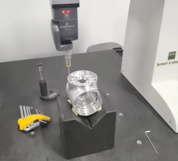
A typical CMM uses orthogonal X, Y, and Z axes with high-resolution scales. The probing system contacts or scans the part surface to collect point data. These measured points are then mathematically processed to construct features (such as planes, cylinders, cones, spheres, and freeform surfaces) and to evaluate dimensional and geometric tolerances.
In CNC production, CMM inspection is applied in first article inspection, in-process dimensional checks, and final inspection. It supports process capability studies, fixture validation, and correlation with on-machine probing datasets.
Types of CMMs Used for Machined Parts
Different CMM configurations are used depending on part size, accuracy requirements, and production environment. Selecting the appropriate CMM type is important for reliable and efficient inspection.
| CMM Type | Key Characteristics | Typical Applications |
|---|---|---|
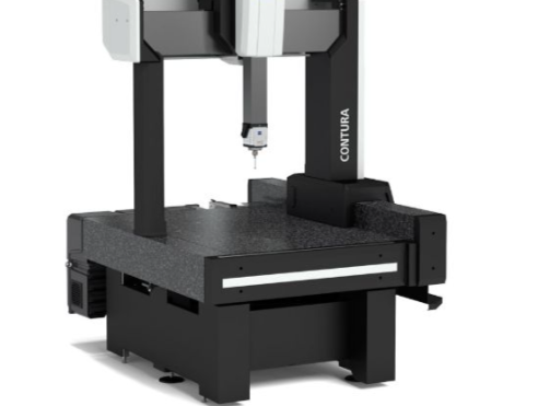
| Bridge CMM | High accuracy, stable structure, usually in a temperature-controlled room | Precision prismatic parts, small to medium components, tighter tolerances |
| Gantry CMM | Large measuring volume, robust frame, can handle heavy workpieces | Large aerospace, automotive body, and heavy machined components |
| Horizontal Arm CMM | Side-mounted arm, easy access to large parts, flexible layout | Body-in-white, large castings, complex assemblies |
| Shop-Floor CMM | Thermal compensation, sealed guides, robust design for production areas | In-process inspection close to CNC machines, fast feedback to production |
| Portable CMM (Articulated Arm) | Mobile, flexible, lower accuracy than high-end bridge CMMs | On-machine checks, large part features, reverse engineering |
| Optical / Multisensor CMM | Non-contact, can include vision, laser, and tactile probes | Delicate surfaces, small features, plastic and electronic parts |
CNC Machining 101For typical precision CNC machined metal parts, bridge and shop-floor CMMs with tactile probes are widely used due to their balance of accuracy, speed, and robustness.
Key CMM Components and Their Functions
The performance of CMM inspection depends on several main components. Understanding their function helps in selecting equipment and setting up reliable measurement routines.
- Machine structure and axes
- Probe system
- Controller and drive system
- Scale system and encoders
- Software and user interface
- Environmental monitoring system
The machine structure (granite table, bridge, and moving axes) provides mechanical stability. The probing system (touch-trigger, scanning, or optical) interacts with the workpiece. The controller interprets motion commands and closes control loops. Linear scales provide precise position feedback. Metrology software performs feature construction, GD&T evaluation, and reporting. Environmental sensors record temperature and, if available, compensate for thermal expansion.
Measurement Principles and Coordinate Systems
CMM inspection is based on Cartesian coordinate measurement in three dimensions. The machine coordinate system is defined by the physical axes. To measure a part, a workpiece coordinate system is established using datum features specified on the drawing or CAD model.
Fundamental elements of CMM measurement principles include:
- Point sampling: discrete contact or non-contact points on surfaces
- Feature fitting: least-squares, minimum zone, or other algorithms to define geometric features
- Alignment: transformation of measured data into the part coordinate system
- Compensation: thermal compensation and probe calibration corrections
A typical part alignment uses three datum elements: a primary datum plane, a secondary datum (line or plane), and a tertiary datum point or edge. These define the origin and orientation of the coordinate system, directly influencing all subsequent measurements.
Dimensional and Geometric Tolerances in CMM Inspection
CMMs are particularly suited to verifying GD&T (Geometric Dimensioning and Tolerancing) on CNC machined parts. Dimensional tolerances specify size limits; geometric tolerances control form, orientation, location, and runout.
Common GD&T characteristics evaluated by CMM include:
Form tolerances (flatness, straightness, roundness, cylindricity) are evaluated by analyzing deviations of the measured surface from an ideal geometry without reference to datums. Orientation tolerances (parallelism, perpendicularity, angularity) refer to datums and are evaluated by calculating angular and distance deviations. Positional tolerances (true position, concentricity, symmetry) control the location of features relative to datum systems. Profile tolerances control the shape of surfaces or lines according to CAD geometry or ideal curves.
Precise implementation in CMM software requires correct definition of datum reference frames, material modifiers (MMC/LMC), and tolerance zones. Correct sampling strategies (number and distribution of points) are critical to obtain representative results, especially for complex contour and freeform surfaces.
Typical Tolerance Ranges and CMM Accuracy Requirements
The required measurement accuracy depends on the tolerances of the machined part. A common engineering rule is that the measurement uncertainty should be no more than 1/10 to 1/3 of the tolerance band, depending on quality requirements.
Typical scenarios for CNC machined parts include:
General mechanical parts may have length and diameter tolerances in the range of ±0.05 mm to ±0.1 mm, requiring CMM volumetric accuracy on the order of 2–5 μm for reliable verification. Precision aerospace and automotive components often have tolerances between ±0.005 mm and ±0.02 mm, where CMMs with volumetric accuracy around 1.5–3 μm are commonly used. High-precision components for optics, instrumentation, or medical devices can have tolerances down to a few micrometers, which may require dedicated high-accuracy CMMs or special setups.
Material thermal expansion must be considered. For example, steel with a coefficient of thermal expansion roughly 11.5 μm/(m·°C) can exhibit dimensional changes beyond tolerance if temperature deviates from the reference condition (usually 20 °C) and is not compensated.
Probing Technologies for CNC Machined Parts
The probing system determines how the CMM interacts with the part and strongly affects measurement speed and uncertainty.
| Probe Type | Measurement Principle | Typical Use on Machined Parts |
|---|---|---|
| Touch-Trigger Probe | Detects contact when stylus deflects and triggers a single point | General dimensional checks, prismatic features, first article inspection |
| Scanning Probe | Continuously measures while stylus moves along surface | Profiles, freeform surfaces, form tolerances, high point density |
| Indexing Probe Head | Rotational positions in fixed increments | Access to multiple feature orientations without re-fixturing |
| Motorized Continuous Head | Continuously variable orientation | Complex geometries, multi-angle measurements, deep features |
| Optical / Vision Probe | Image processing and edge detection | Small features, slots, delicate surfaces, non-contact measurement |
| Laser Distance Probe | Non-contact distance measurement with laser beam | Surface profiles, soft materials, fast scanning of large areas |
Stylus selection is equally important. Common materials are ruby and silicon nitride balls in diameters from approximately 0.3 mm up to several millimeters. Styli length and stiffness must be chosen to minimize deflection while ensuring access to the measured features, particularly for deep bores, undercuts, and pocket features typical of CNC machining.
Inspection Process Flow for CNC Machined Parts
A systematic process flow is essential for consistent CMM inspection. For CNC machined parts, the process generally includes:
Preparation includes reviewing drawings or CAD data, defining inspection requirements, and selecting or creating the CMM program. Fixtures and clamping methods are chosen to ensure stable and repeatable positioning. Part handling must minimize mechanical stress and contamination.
Part setup involves cleaning the part, mounting it on the CMM table or fixture, and roughly aligning it based on reference features or tooling holes. The CMM operator calls the appropriate program or initiates manual measurement if required.
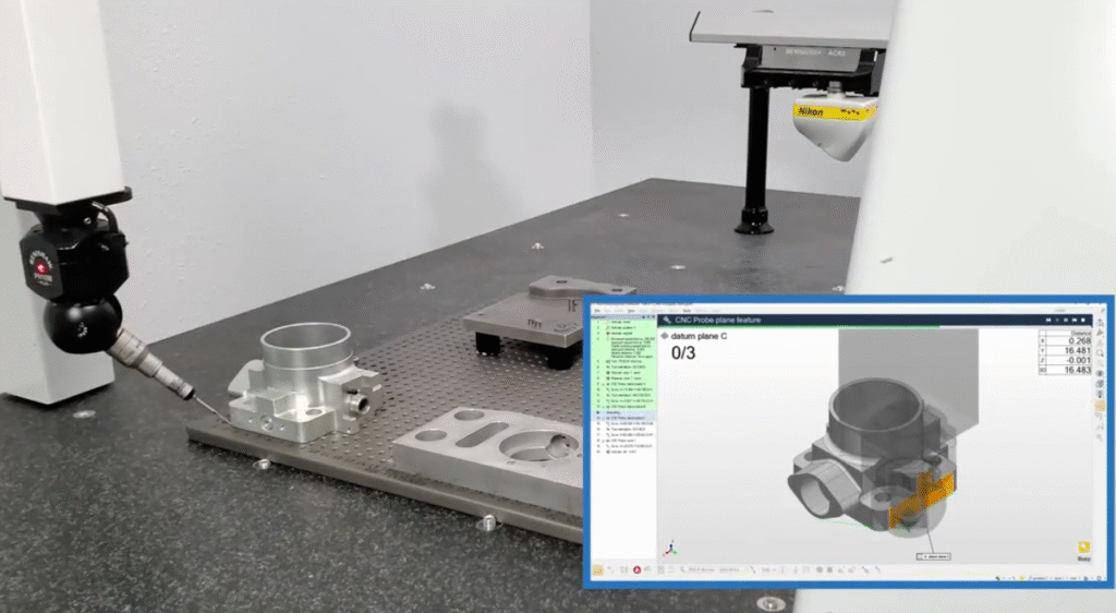
Datum and alignment acquisition defines the workpiece coordinate system. Typical alignment uses three mutually orthogonal datum elements: primary plane to establish orientation and two axes, secondary feature to define a direction, and tertiary feature to establish the origin.
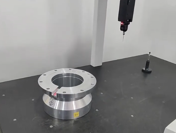
Feature measurement is performed according to the inspection plan. The CMM measures key dimensions such as hole diameters, positions, slot widths, surface profiles, and threads. The measurement strategy (points, lines, circles, scanning paths) is adapted to each feature type and tolerance requirement.
Data evaluation compares measured values to nominal values, calculating deviations, tolerance utilization, GD&T results, and statistical indicators. Non-conformances are flagged and may trigger re-measurement or process investigation.
Reporting and archiving complete the flow with electronic or printed reports, data storage in databases, and traceability records linked to part numbers, batch numbers, and machine settings. This structure supports ongoing process optimization and documentation requirements for regulated industries.
CMM Programming and Automation
CMM inspection programs define the sequence of machine movements, probe changes, feature measurements, and data evaluations. For CNC machined parts, programs can be created manually at the machine or offline using CAD models.
Manual programming uses joystick control and interactive feature definition. It is suitable for simple parts or small series. Offline programming uses CAD-based software. The user imports the CAD model, defines features and tolerances, and simulates the probe paths. The resulting program is transferred to the CMM, reducing machine downtime.
Key aspects of CMM programming for CNC parts include avoiding collisions with clamps, fixtures, and part geometry; optimizing probe path to reduce travel time; implementing automatic probe qualification and change routines; and standardizing naming conventions for features and reports. When automation is implemented, CMMs can be integrated with pallet systems or robotic loaders, enabling unattended inspection of batches of machined parts.

Inspection Planning and Feature Selection
Inspection planning defines what to measure, how often, and with which methods. For CNC machined parts, it must balance risk, cost, and production speed.
An inspection plan typically identifies safety-critical and function-critical features that require 100% inspection, such as mating surfaces, sealing faces, bearing seats, and threaded connections. Other dimensions may be inspected on a sampling basis according to statistical quality control rules.
Critical dimensions are derived from functional requirements, tolerance stack-ups, and history of process capability. The plan specifies the measurement strategy for each feature: number of points, distribution pattern, scanning speed, and evaluation method. Integration with process control ensures that measurement results are fed back to CNC programming and tool management when systematic deviations are detected.
Fixturing and Setup Considerations
Reliable fixturing is essential for repeatable measurement. Fixtures for CMM inspection must hold the part securely without introducing significant deformation or obstructing access to critical features.
For CNC machined parts, modular fixturing systems with plates, columns, clamps, and locating pins are commonly used. Features used as datums in machining and inspection should be consistent to avoid coordinate mismatches. Fixture materials with low thermal expansion and high rigidity improve stability.
Key considerations include using three-point support for planar parts to avoid over-constraint; avoiding clamping on thin-walled areas to prevent elastic deformation; orienting parts such that major surfaces are easily accessible; and ensuring that fixtures are themselves inspected or referenced to the CMM coordinate system to maintain traceability.
Environmental and Thermal Control
CMM accuracy is sensitive to environmental conditions, especially temperature. Dimensional measurements are typically referenced to 20 °C. Deviations from this temperature cause expansion or contraction of both the machine and the part.
Best practice is to perform CMM inspection in a controlled environment with stable temperature, limited air flow, and low vibration. Shop-floor CMMs incorporate thermal compensation models, vibration isolation, and encapsulated guideways to mitigate environmental influences.
For CNC machined parts, temperature equalization is important. Parts should be allowed sufficient time to equilibrate to the inspection room temperature, especially if they were previously in a different environment or experienced heat during machining. Contact temperature from operator handling must also be minimized for high-accuracy work.
Measurement Strategies for Common CNC Features
CNC machined parts often contain recurring types of features. Efficient, standardized measurement strategies can be applied to these.
For planar surfaces, point grids or scanning paths are used to evaluate flatness, parallelism, and thickness. A limited number of points may be adequate for general tolerances, while tighter requirements demand denser sampling. For holes and bores, multiple points on several circles or helical scanning can determine diameter, cylindricity, and position. Counterbores and countersinks can be evaluated by measuring both diameter and depth, referencing functional datums.
Complex pockets and slots are measured by sampling corner radii, side wall straightness, bottom flatness, and width. Threaded features are commonly evaluated via pitch diameter, position, and perpendicularity by using specialized thread probes or by gauging techniques correlated with CMM reference features.
Freeform surfaces are measured with scanning probes or optical sensors, generating point clouds that are compared to CAD nominal surfaces using color maps and deviation statistics.
Data Analysis, Reporting, and Traceability
CMM software offers extensive data processing capabilities. Measurement results are typically analyzed on two levels: individual feature compliance and overall part conformance.
Feature-level analysis includes actual values versus nominal, deviations, tolerance consumption, and GD&T acceptance. For series production, statistical indicators such as mean, standard deviation, Cp, and Cpk are calculated to evaluate process capability.
Reports can be tailored for operators, engineers, and customers. Standard elements are feature lists with measured values, pass/fail status, graphical representation of measured features, deviation color maps for surfaces, and details on alignment, probe configurations, and environmental conditions.
Traceability requires linking each inspection report to part identifiers, machining programs, tools, operators, and calibration records. This connection is essential for root cause analysis when deviations are detected and for compliance with quality management standards.
Integration of CMM Inspection with CNC Production
Coordination between CMM inspection and CNC machining increases productivity and reduces scrap. By using consistent datums and reference systems, measurement results can be directly translated into machining offsets.
Typical integration methods include using the same datums and reference holes in CAM programming and CMM programs; transferring measurement data into machine tool controllers to adjust tool offsets or workpiece coordinates; performing first article inspection to validate new programs or setups before full production; and using statistical trends to schedule tool changes or maintenance before tolerances are exceeded.
In a more advanced setup, closed-loop workflows connect CAD/CAM, CMM programming, and CNC control, enabling rapid feedback and consistent geometric quality over long production runs.
Common Issues and Considerations in CMM Inspection
Several practical considerations influence the reliability of CMM inspection for machined parts. Typical issues include insufficient part cleaning, which leads to measurement errors caused by chips, coolant, or oil residues; misinterpretation of drawings or GD&T specifications, resulting in incorrect alignment or evaluation methods; inadequate distribution of measurement points, which can underestimate form deviations; and inappropriate styli selection or worn probe tips, causing systematic measurement bias.
Other considerations are fixturing that distorts thin parts or restricts access to critical features, inadequate environmental control leading to thermal drift, and insufficient correlation between CMM and shop-floor measurement devices. Systematic verification and calibration routines, clear work instructions, and training for metrology personnel help mitigate these issues.
FAQ about CMM Inspection for CNC Machined Parts
What is CMM inspection for CNC machined parts?
CMM (Coordinate Measuring Machine) inspection is a precision measurement process used to verify the dimensional accuracy and geometric tolerances of CNC machined parts by probing multiple points on the component in a 3D coordinate system.
Why is CMM inspection important for CNC machined parts?
CMM inspection ensures that machined parts meet design specifications, GD&T requirements, and quality standards. It helps detect deviations early, improves consistency, and guarantees reliable fit and performance in assembly.
What types of measurements can a CMM perform?
A CMM can measure dimensions, flatness, parallelism, perpendicularity, concentricity, position, profile, and other geometric tolerances with high accuracy and repeatability.
Can CMM inspection reports be provided to customers?
Yes. Detailed CMM inspection reports, including dimensional results and tolerance compliance, can be provided upon request to support quality documentation and traceability.
Does CMM inspection replace traditional measuring tools?
While traditional tools like calipers and micrometers are useful for basic checks, CMM inspection is essential for complex geometries and tight tolerances that require comprehensive and repeatable measurement.
