
Coordinate Measuring Machines (CMMs) are core instruments for dimensional inspection in precision manufacturing. Their usefulness depends on well-defined and verified performance: accuracy, repeatability, and adherence to tolerance standards. This document provides a systematic and technical overview of the key concepts, parameters, standards, and practical methods used to specify, verify, and apply CMM performance in industrial environments.
Fundamental Concepts: Accuracy, Repeatability, Precision, and Uncertainty
Before addressing formal standards, it is essential to define the main metrological concepts used for CMM performance evaluation.
Accuracy
CMM accuracy describes how close a measurement result is to the true value or a reference standard. For a given measurand, accuracy reflects the combined influence of systematic errors such as scale errors, geometric errors, probe calibration errors, and environmental effects.
For CMMs, accuracy is usually expressed as a maximum permissible error (MPE) related to length measurement or probing performance. Standards such as ISO 10360 define accuracy in terms of MPE values that must not be exceeded under specified test conditions.
Repeatability and Precision
Repeatability refers to the closeness of agreement between successive measurements of the same measurand carried out under identical conditions (same operator, same CMM, same procedure, same environment, short time interval). It is often quantified statistically by standard deviation or range of repeated readings.
Precision is a broader term that includes repeatability (same conditions) and sometimes intermediate precision or reproducibility (different conditions, operators, or time periods). For CMM users, repeatability is a direct indicator of short-term stability and noise in the measurement system.
Measurement Uncertainty
Measurement uncertainty quantifies the dispersion of values that could reasonably be attributed to the measurand. It combines contributions from the CMM, environment, workpiece, fixturing, probing strategy, software, and operator. While accuracy expresses maximum error limits, uncertainty provides a probabilistic assessment of measurement quality.
Industrial dimensional inspections increasingly require an uncertainty budget according to the Guide to the Expression of Uncertainty in Measurement (GUM) or related guidance documents. CMM manufacturers often provide baseline uncertainty data for the machine, which users must extend to full measurement processes.
Key CMM Performance Parameters
CMM performance is specified using a set of standardized parameters that describe length measurement, probing behavior, and volumetric performance. These parameters are defined in ISO 10360 series and other regional or application-specific standards.
Length Measurement Error (E)
Length measurement error describes the deviation between a measured distance and its reference value. According to ISO 10360-2, it is typically specified as:
E = A + L/k
where A is a constant term (µm), L is the measured length (mm), and k is a scaling factor (often 1000, 500, or 250 depending on CMM class and manufacturer). This expression captures both fixed and length-dependent errors.
Probing Errors (P) and Form Errors
Probing performance is characterized by several parameters:
- Probing form error: deviation of stylus tip path from an ideal geometric feature, usually a sphere or plane.
- Probing size error: difference between measured size of a reference artifact and its calibrated value.
- Probing repeatability: variation in repeated probing of the same point or feature under identical conditions.
These parameters describe how reliably the probing system, including stylus, probe head, and trigger mechanism, captures surface points.
Volumetric and Positioning Errors
Volumetric performance describes CMM accuracy across the working volume, including combined effects of linear positioning errors, straightness, squareness, and rotation of each axis. Volumetric tests are often conducted using calibrated step gauges, ball bars, or multi-sphere artifacts.
Positioning errors include linear scale errors, backlash, and servo-related deviations. These are typically corrected by geometric compensation, but residual errors define the ultimate volumetric accuracy of the machine.
International and Industrial Standards for CMM Performance
Several standards define how CMM performance is specified, tested, and reported. The ISO 10360 series is globally prevalent, while some industries may also refer to ASME standards and GD&T practices.
ISO 10360 Series
The ISO 10360 series is the foundational set of international standards for acceptance and reverification tests on CMMs. While the series covers different machine types and probing systems, key parts include:
- Length measurement error testing with step gauges, gauge blocks, or interferometric setups.
- Probing performance testing with calibrated spheres or reference artifacts.
- Guidance on environmental conditions, measurement procedures, and result reporting.
Manufacturers specify CMM performance using MPE values that must comply with ISO 10360 test methods.
ASME and Related Standards
In addition to ISO 10360, users may apply American standards such as ASME B89 series for CMM performance specifications and procedures. Many users also rely on ASME Y14.5 or ISO GPS standards for geometric dimensioning and tolerancing (GD&T), which define the tolerances that CMMs must verify on parts.
The interplay between CMM performance standards (ISO 10360, ASME B89) and GD&T standards (ASME Y14.5, ISO 1101 and related) is crucial for defining realistic measurement capabilities and limitations.
Manufacturer Specifications and MPE Values
CMM manufacturers provide performance specifications in terms of MPE for length measurement, probing, and sometimes additional parameters. Users must verify that these MPE values are adequate for their application tolerances and processes.
Specifications normally include the measurement volume, MPE formulas or tabulated limits, accepted test procedures, environmental requirements, and probe configurations under which the MPE is valid.
MPE, MPEE, MPL and Related Specification Metrics
Maximum permissible error (MPE) parameters define the upper limits of CMM error under specific standardized test conditions. They provide a clear and verifiable performance guarantee that connects directly to acceptance and comparison of machines.
MPE for Length Measurement (MPEE)
MPE for length measurement, often designated as MPEE, describes the maximum allowed error when measuring calibrated distances using the CMM. It is usually expressed as a function of length, for example:
MPEE = (1.5 + L/350) µm
This means the maximum error increases with measurement length L (in mm), where 1.5 µm is a constant term and L/350 reflects length-dependent scaling. Different machines may use different coefficients depending on accuracy class and mechanical configuration.
MPE for Probing Performance (MPEP)
MPEP quantifies maximum permissible errors in probing performance. Common metrics include:
- Probing sphere form error: maximum radial deviation when probing a calibrated sphere.
- Probing sphere size error: difference between measured and reference sphere diameter.
- Probing repeatability limits for repeated contact of the same location.
These parameters are critical because they influence the implicit uncertainty of measured feature coordinates and derived dimensions.
MPL and Other Specific Parameters
Some specifications use parameters such as MPL (maximum permissible length error for linear positioning along a single axis) or similar terms for squareness and straightness errors. These values describe single-axis errors that contribute to the overall volumetric error.
In practice, MPEE and MPEP are most commonly referenced by users, with additional parameters used by metrology engineers and service providers for detailed error analysis and compensation.
CMM Calibration, Verification, and Traceability
To maintain the specified accuracy and repeatability, CMMs require calibration and periodic verification under controlled conditions, ensuring traceability to national or international standards.
Calibration Artifacts
CMM calibration and verification use certified artifacts with traceable dimensions and associated uncertainties. Typical artifacts include:
- Gauge blocks and step gauges for linear measurements.
- Calibrated spheres, sphere plates, and ball bars.
- Ring gauges, plug gauges, and multi-feature blocks for form and position checks.
Each artifact has a documented calibration certificate that provides reference values and uncertainties from a higher-level metrology laboratory.
Traceability Chain
Traceability ensures that measurements made on the CMM are linked through an unbroken chain of calibrations to national or international standards. This chain typically includes:
National metrology institute → accredited calibration laboratory → CMM artifacts → CMM performance values → measured parts.
Maintaining traceability requires regular calibration of artifacts, documented procedures, and systematic record keeping.
Verification Intervals
Verification intervals depend on factors such as machine utilization, environmental control, quality system requirements, and client or regulatory demands. Common practices include:
- Daily or per-shift quick checks using simple artifacts (e.g., a reference sphere).
- Periodic formal verifications (monthly, quarterly, or annually) according to ISO 10360 or equivalent procedures.
- Recalibration after relocation, major maintenance, or suspected performance drift.
Measurement Uncertainty in CMM Applications
CMM measurement uncertainty is increasingly required for capability studies, customer documentation, and compliance with quality standards. It must consider both the CMM and the complete measurement process.
Uncertainty Components
Typical uncertainty contributions include:
- CMM systematic and random errors (MPEE, MPEP, scale errors, geometric deviations).
- Environmental conditions (temperature gradients, humidity, vibrations, air flow).
- Workpiece-related factors (thermal expansion, surface roughness, material stability).
- Probing strategy (number of points, probing speed, approach direction).
- Software algorithms (fitting routines, filter settings, compensation models).
- Operator influence (setup, fixturing, alignment choices).
Budgeting and Reporting
Uncertainty budgeting usually follows GUM concepts: identifying sources, assigning distributions, combining standard uncertainties, and applying coverage factors to obtain expanded uncertainty. The resulting value is often reported along with the measurement result, for example:
Measured diameter: 50.012 mm ± 0.004 mm (k = 2)
Users may use published guidelines specifically addressing uncertainty for CMM-based coordinate metrology, which provide simplified models for practical industrial applications.
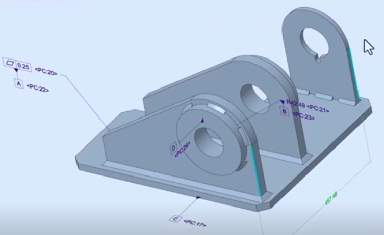
Geometric Tolerances and CMM Capability
CMMs are widely used to verify geometric tolerances such as position, flatness, cylindricity, and orientation. The relationship between CMM performance and the GD&T requirements on the drawing determines whether reliable conformance statements can be made.
Relation to ASME Y14.5 and ISO GPS
ASME Y14.5 and ISO GPS standards define how geometric characteristics and tolerances are specified. These tolerances describe allowable variation in form, orientation, location, and runout. The CMM must be able to resolve these tolerances with sufficient accuracy and uncertainty margins.
For example, verifying a flatness tolerance of 0.01 mm requires that the CMM’s measurement uncertainty for that feature be significantly smaller than the tolerance, typically by a factor chosen based on company policy or industry practice.
CMM Capability versus Drawing Tolerances
To evaluate whether a CMM is capable of verifying a given tolerance, users compare the expanded measurement uncertainty to the tolerance size. A common consideration is that uncertainty should occupy only a limited portion of the tolerance band to avoid ambiguous results near the tolerance limits.
Users sometimes define internal rules such as requiring that the expanded uncertainty be less than a specified fraction of the tolerance (for example, less than 1/4 or 1/3 of the tolerance width). Such rules are not universal but help create consistent acceptance criteria.
Environmental and Installation Requirements
CMM performance strongly depends on installation conditions and environmental control. A machine that meets specified MPE values in a controlled laboratory may not achieve the same performance in an uncontrolled shop floor environment.
Temperature Control and Thermal Effects
Most CMM specifications assume operation at or near 20 °C with limited temperature variation. Thermal expansion of both the machine structure and the workpiece leads to length changes that directly impact measurement results.
Key aspects include:
- Ambient temperature stability over time.
- Temperature gradients along machine axes and workpiece.
- Use of thermal compensation systems and correct material coefficients.
Even with temperature compensation, excessive gradients or rapid fluctuations degrade accuracy and repeatability.
Vibration and Foundation
CMMs are sensitive to dynamic disturbances. Vibration from nearby machining centers, forklift traffic, or building infrastructure can introduce measurement noise and instability. Appropriate foundations or isolation systems are often required, especially for high-accuracy machines.
Air Quality and Cleanliness
Contamination such as dust, oil mist, or chips affects guideways, scales, and probing reliability. Clean environments and regular maintenance are necessary to maintain specified performance over time.
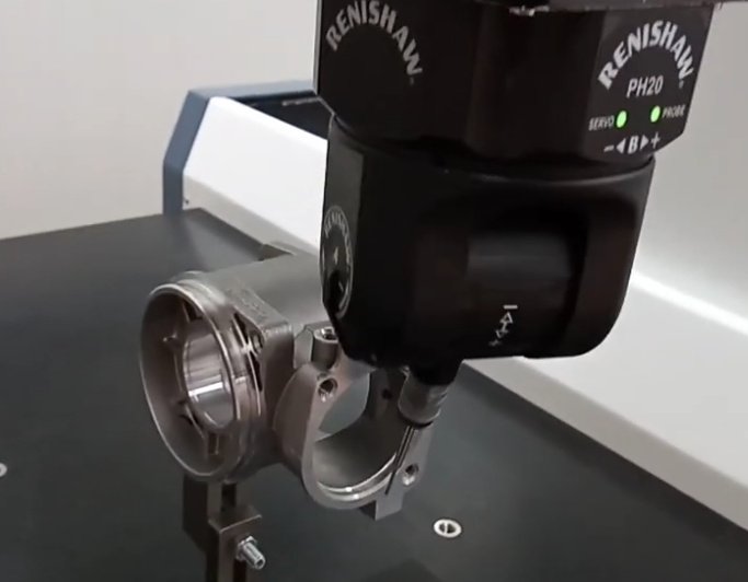
Probing Systems, Stylus Configuration, and Their Impact
Probing systems are critical elements in CMM performance. Mechanical trigger probes, analog scanning probes, and optical or multi-sensor heads each have distinct characteristics that influence accuracy and repeatability.
Probe Types and Performance
Mechanical touch-trigger probes provide discrete points and are widely used for general inspection. Scanning probes acquire large point clouds by continuous contact and are suitable for form and profile evaluation. Non-contact probes (optical, laser) are used for delicate or soft surfaces where mechanical contact is not acceptable.
Each probe type has specified probing errors and repeatability characteristics, which must be considered when selecting the system for a given tolerance and feature complexity.
Stylus Length, Stiffness, and Configuration
Stylus geometry directly affects probing performance. Longer styli or multi-piece configurations increase deflection and sensitivity to dynamic effects, often resulting in larger probing errors. CMM specifications are usually based on particular stylus arrangements; deviations from these arrangements can reduce actual performance.
It is important to consider stylus stiffness, material, diameter, and connection type, as well as the number of styli on indexing heads or multi-sensor turrets, when planning measurement tasks.
Measurement Strategies and Software Considerations
Even with a high-performance CMM, the chosen measurement strategy and software settings have a strong influence on effective accuracy and repeatability.
Point Density and Distribution
The number and distribution of measurement points affect the reliability of feature fitting and form evaluation. Sparse point sets may underestimate local deviations, while dense sampling improves coverage but increases measurement time and data processing complexity.
Alignment and Datum Schemes
Part alignment defines the coordinate system in which features are evaluated. Misaligned datums or inconsistent alignment strategies introduce additional errors and reduce comparability of results. Robust and well-documented datum schemes are essential for reliable and repeatable inspections.
Software Algorithms and Filtering
Different CMM software packages implement various fitting algorithms (least squares, minimum circumscribed, maximum inscribed, etc.) and surface filtering options. These choices can significantly affect measured sizes and geometric characteristic values, especially for rough or imperfect surfaces.
A clear understanding of software settings, algorithm definitions, and their relation to the applicable GD&T standards is required to ensure correct interpretation of results.
Typical Pain Points in Applying CMM Standards
In industrial use, several recurring issues arise when applying CMM accuracy, repeatability, and tolerance standards.
Misinterpretation of MPE Specifications
Users sometimes treat MPEE or MPEP as guaranteed errors for any measurement under any condition. In reality, MPE values are valid only under specified conditions (environment, artifact type, probing configuration). When conditions differ, actual errors may be larger, leading to unexpected discrepancies between theoretical and observed performance.
Insufficient Connection between Tolerances and CMM Capability
Drawings may include very tight tolerances without verification that the available CMMs and measurement processes can support them with adequate uncertainty margins. This mismatch results in inconclusive pass/fail decisions and disputes between manufacturing and quality departments or between supplier and customer.
Inadequate Environmental Control
Relocating a CMM from a metrology lab to a shop floor without appropriate environmental measures can compromise performance. Machines may still be within official MPE limits during short-term tests, yet experience larger errors over a full production cycle due to thermal and vibration effects that were not considered in initial acceptance tests.
Example CMM Specification Parameters
The following table illustrates how CMM performance parameters might be presented. Values are indicative and not tied to a specific commercial product.
| Parameter | Symbol | Example Specification | Conditions |
|---|---|---|---|
| Length measurement MPE | MPEE | (1.5 + L/350) µm | L in mm, temperature 20 ± 1 °C |
| Probing form error on reference sphere | MPEP_form | 1.0 µm | Styli length 50 mm, standard sphere |
| Probing size error on reference sphere | MPEP_size | 1.5 µm | Same configuration as form test |
| Single-axis positioning error | MPL | (1.0 + L/500) µm | Measured along each axis |
| Repeatability of probing a single point | R_pt | σ ≤ 0.5 µm | n = 25 repeat touches |
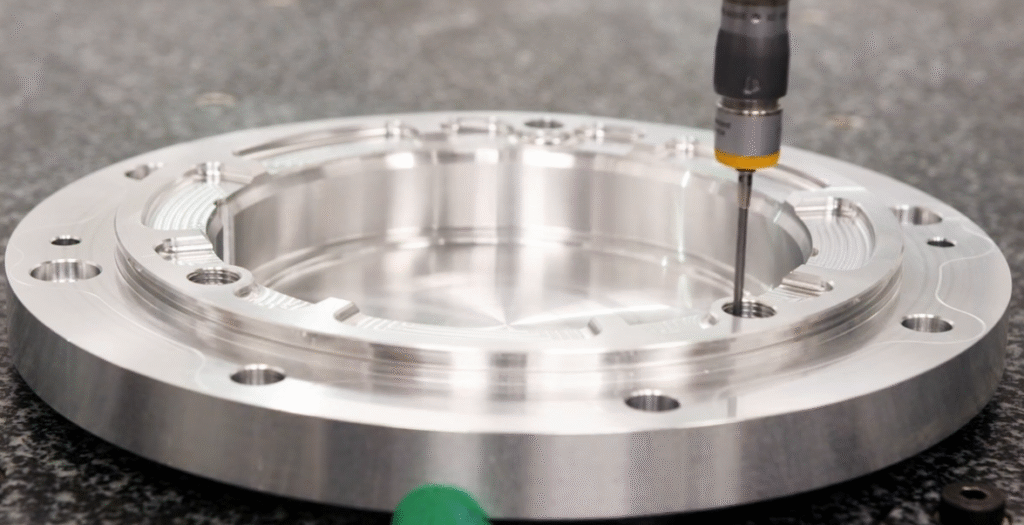
Example Verification Tasks and Interpretation
The following example illustrates how verification tasks relate to CMM standards and specifications in practice.
Length Measurement Verification
Using a calibrated step gauge, the CMM measures multiple distances distributed across the measurement volume. For each distance, the deviation from the certificate value is computed. The maximum absolute deviation must not exceed the specified MPEE formula over the range of tested lengths.
Probing Performance Verification
A calibrated reference sphere is probed at multiple points around its surface. The fitted sphere’s form deviation and size deviation are evaluated. These results must be less than or equal to the corresponding MPEP values. Repeatability is also checked by repeatedly probing a single surface location and calculating the standard deviation.
Interpreting Verification Results
If measured errors remain within MPE limits, the CMM is considered compliant with its specification. Users may then use this verified performance, together with other process contributions, to build measurement uncertainty budgets and demonstrate capability for their inspection tasks.
Practical Guidelines for Selecting and Using CMMs
When selecting or applying a CMM, several practical guidelines help ensure that accuracy, repeatability, and tolerance requirements are met.
Matching CMM Specifications to Application Needs
Users should compare CMM MPE values with their smallest critical tolerances and required measurement uncertainty. A machine with overly coarse performance relative to tolerances may lead to unreliable pass/fail decisions, while excessively tight CMM performance may increase acquisition costs without proportional benefit.
Establishing Measurement Procedures
Documented measurement procedures should define artifacts, calibration and verification frequencies, alignment strategies, probing patterns, sampling density, software settings, and environmental checks. Consistent procedures reduce variability and improve traceability across shifts, operators, and facilities.
Monitoring Performance Over Time
Trend monitoring using regular verification results helps detect gradual changes in CMM performance. Early identification of drift allows planned maintenance or recalibration before major deviations affect product quality or customer acceptance.

Comparison of Common CMM Test Artifacts
Different artifacts emphasize different aspects of CMM performance. The table below compares some commonly used artifact types in acceptance and reverification tasks.
| Artifact Type | Primary Purpose | Typical Parameters Evaluated | Advantages |
|---|---|---|---|
| Step gauge | Length measurement accuracy | MPEE, MPL, scale linearity | Multiple calibrated distances, compact form |
| Gauge blocks | Short-distance verification | Short-range E errors | High accuracy, flexible configurations |
| Reference sphere | Probing performance | MPEP_form, MPEP_size, repeatability | Simple setup, daily checks possible |
| Ball bar or multi-sphere artifact | Volumetric performance | 3D volumetric error, squareness | Covers larger volume in fewer setups |
| Multi-feature test block | Application-like verification | Combined lengths, angles, GD&T | Simulates real parts and strategies |
Conclusion
CMM accuracy, repeatability, and tolerance standards form an integrated framework that connects machine specifications, international standards, calibration and verification methods, measurement uncertainty, and practical inspection tasks. By understanding key concepts such as MPEE, MPEP, GD&T requirements, environmental influences, probing strategies, and uncertainty contributions, users can select appropriate CMMs, establish robust procedures, and maintain reliable measurement systems over the entire lifecycle of their equipment.
FAQ
What is CMM accuracy?
CMM accuracy refers to how close a measured value is to the true or nominal dimension of a part. It is typically specified in microns and depends on machine design, calibration, environment, and probe system.
What is repeatability in a CMM?
Repeatability is the CMM’s ability to produce the same measurement result when measuring the same feature multiple times under the same conditions.
What is the main difference between accuracy and tolerance?
Accuracy relates to measurement correctness, while tolerance relates to design limits. Accuracy applies to the measuring system; tolerance applies to the part.
What tolerance standards are used for CMM measurement?
Common standards include ISO 10360, ASME B89, and VDI/VDE 2617, which define performance requirements for CMM accuracy, probing error, and volumetric length measurement.
