
CAD and CAM are two core pillars of digital product development and manufacturing. They are closely related, often used together, but they serve different purposes and operate at different stages of the workflow. Understanding the distinction between CAD and CAM is essential for engineers, designers, machinists, and anyone involved in modern manufacturing processes.
Definition of CAD and CAM
CAD and CAM are both computer-based systems, yet each focuses on a different part of the product life cycle.
What is CAD?
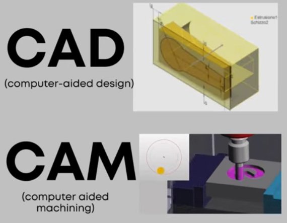
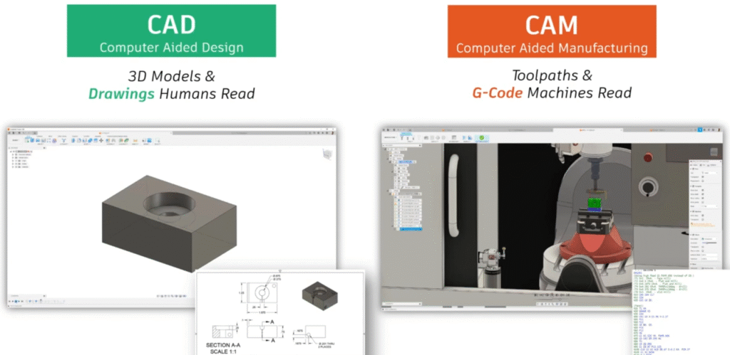
CAD stands for Computer-Aided Design. It refers to software tools used to create, modify, analyze, and document precise digital models of products or components. CAD can represent both 2D geometry and 3D solid or surface models with exact dimensions and constraints. The resulting digital model becomes the master definition of the part or assembly.
Common uses of CAD include creating engineering drawings, defining product geometry, performing design analysis, generating assembly layouts, and preparing data for downstream processes such as CAM, simulation, and documentation.
What is CAM?
CAM stands for Computer-Aided Manufacturing. It refers to software used to plan, manage, and generate machine toolpaths and instructions required to manufacture parts designed in CAD. CAM systems translate digital geometry into machine-readable code, typically G-code or similar formats, which CNC machines use to execute physical operations such as cutting, drilling, turning, or milling.
CAM software focuses on manufacturing strategies, tool selection, machining parameters, and sequencing of operations to transform raw material into finished parts with the required accuracy and surface quality.
Core Purpose and Role in the Workflow
CAD and CAM address different goals in a digital manufacturing workflow, even though they are interconnected.
Primary role of CAD
The primary role of CAD is to create an accurate, modifiable representation of the intended product. CAD answers questions such as:
- What does the part look like?
- What are its dimensions and tolerances?
- How do components fit and interact in an assembly?
- Does the geometry satisfy functional and performance requirements?
CAD prioritizes design correctness, design intent, and geometric accuracy.
Primary role of CAM
The primary role of CAM is to determine how to manufacture the part efficiently and correctly. CAM answers questions such as:
- Which machine and tools will be used?
- What toolpaths are required to remove material or form the part?
- What feeds, speeds, and stepovers should be applied?
- In what sequence should operations be executed to achieve tolerances and surface finish?
CAM prioritizes manufacturability, process efficiency, and safe machine execution.
Technical Characteristics of CAD Systems
CAD systems are built to capture design intent and geometric detail using robust modeling technologies and parametrization methods.
Geometric modeling capabilities
CAD software typically provides several geometric modeling approaches:
- 2D drafting: Lines, arcs, circles, and dimensions for simple layouts and technical drawings.
- 3D wireframe: Edge-based models representing basic shape without surfaces.
- Surface modeling: NURBS surfaces, lofts, sweeps, and blends for complex, freeform shapes.
- Solid modeling: Parametric solid bodies defined by features such as extrudes, revolves, cuts, fillets, and holes.
Modern CAD tools rely heavily on parametric, feature-based solid modeling, which allows dimensions and constraints to drive the shape and update downstream features when changes are made.
Parametric and feature-based design
Parametric CAD systems store a history of design features (e.g., sketches, extrusions, cuts) along with parameters such as dimensions and constraints. When a parameter changes, the model regenerates according to the defined relationships. This approach supports design iterations, configuration changes, and family-of-parts variations.
Features may include:
Holes, pockets, ribs, bosses, patterns, chamfers, fillets, draft angles, shell operations, and many other specialized geometric operations. Relations among parts (mates, constraints, references) define how assemblies behave and move.
Detailing, documentation, and standards
CAD software provides tools to generate and maintain manufacturing documentation, including:
Orthographic views, sectional views, auxiliary views, dimensioning and tolerancing, geometric dimensioning and tolerancing (GD&T) symbols, bill of materials (BOM), exploded views, and notes. Many systems support standard drawing formats and templates aligned with common engineering standards.
Analysis and validation within CAD
Although not strictly part of basic geometry creation, many CAD environments include integrated or associated tools for:
Interference checks in assemblies, mass and center-of-gravity calculations, basic motion simulation, and structural or thermal analysis through links to CAE (Computer-Aided Engineering) tools. These capabilities help validate the design before manufacturing planning begins.
Technical Characteristics of CAM Systems
CAM systems convert design geometry into manufacturing instructions with a focus on cutting strategies, machine kinematics, and material removal.
Interpretation of CAD geometry
CAM software imports or reads CAD geometry using native formats or neutral formats such as STEP or IGES. It then uses this geometry as the reference for toolpath creation. The CAM system must interpret surfaces, edges, and solids accurately to generate correct paths and avoid collisions or gouging.
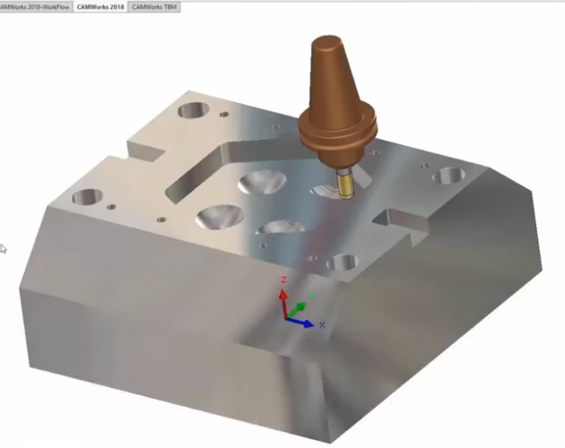
Toolpath generation
Toolpath generation is the core of CAM. It defines the path that the cutting tool will follow relative to the workpiece. Common toolpath categories include:
Facing, contouring and profiling, pocketing, drilling and tapping cycles, roughing operations for bulk material removal, semi-finishing, and finishing paths for final accuracy and surface quality.
CAM software provides options for stepovers, stepdowns, linking moves, ramp entries, and adaptive patterns that control how the tool approaches and leaves the material and how consistent the cutting load is.
Machining strategies and parameters
CAM systems manage machining strategies such as:
Climb vs. conventional milling, high-speed machining patterns, multi-axis approaches (3-axis, 3+2, 4-axis, 5-axis), and rest machining to remove remaining material after earlier operations.
Users specify or select machining parameters, including:
Spindle speed (rpm), feed rate (mm/min or inches/min), feed per tooth, depth of cut, radial and axial engagement, coolant usage, and lead-in/lead-out methods.
These parameters influence cutting forces, tool wear, cycle times, and final part quality.
Post-processing and machine-specific output
Once toolpaths are defined, CAM software performs post-processing to convert generic paths into machine-specific NC code. Post-processors account for:
Machine controller syntax (e.g., Fanuc, Siemens, Heidenhain), kinematic configuration (e.g., 3-axis mill, 5-axis trunnion, turning center), tool change commands, work offset calls, canned cycles, and safety blocks.
The resulting output is typically G-code or a similar language, which the CNC machining machine reads and executes.
Side-by-Side Comparison of CAD and CAM
The following table summarizes fundamental differences between CAD and CAM while highlighting how each contributes to the manufacturing pipeline.
| Aspect | CAD (Computer-Aided Design) | CAM (Computer-Aided Manufacturing) |
|---|---|---|
| Primary Purpose | Create and define product geometry and design intent | Plan and control manufacturing operations based on the design |
| Main Output | 3D models, 2D drawings, assemblies, design documentation | Toolpaths, NC programs (e.g., G-code), machining setup data |
| Focus Area | Accuracy of geometry, function, fit, aesthetics, and constraints | Machining efficiency, manufacturability, cycle time, and process reliability |
| Users | Design engineers, product developers, drafters | CAM programmers, CNC machinists, manufacturing engineers |
| Key Functions | Modeling, drafting, assemblies, tolerancing, basic analysis | Toolpath creation, tool selection, machining strategy, post-processing |
| Input Data | Design requirements, functional specifications, standards | CAD geometry, material data, machine and tooling capabilities |
| Output Use | Reference for analysis, documentation, and manufacturing planning | Direct control of CNC machines and manufacturing operations |
| Data Formats | Native CAD formats, STEP, IGES, DXF, DWG, etc. | NC code, setup sheets, simulation files, tool libraries |
Data Formats and Interoperability
Efficient communication between CAD and CAM requires reliable data exchange. Geometry must be transferred without loss of fidelity, especially for tightly toleranced parts or complex surfaces.
Common CAD file formats used by CAM
CAM systems typically work with:
Native CAD files from major CAD platforms (when supported), STEP (ISO 10303) for solid and surface geometry, IGES for curves and surfaces, Parasolid or similar kernel-based formats, and 2D formats like DXF or DWG for profiles and simple parts.
Using solid-based formats often improves robustness in CAM because the model carries complete volumetric information rather than just surfaces or wireframes.
Considerations in data translation
When transferring data between CAD and CAM, several factors must be considered:
Tolerance settings during export and import, surface continuity and trimming accuracy, unit consistency (metric or imperial), and orientation and coordinate systems. Careful handling of these factors reduces the risk of gaps, overlaps, or misaligned geometry that could lead to incorrect toolpaths or rework.
CAD-to-CAM Workflow in Manufacturing
CAD and CAM are most effective when they operate in a coordinated workflow from product definition to finished part. The basic flow, regardless of specific software, follows a set of consistent steps.
From design to manufacturing preparation
First, the product or component is modeled in CAD. The designer defines geometry, materials, tolerances, and any functional requirements. After design validation, the final CAD model is released for manufacturing.
At this stage, manufacturing engineers or CAM programmers receive the design and begin preparing for machining. They may request design adjustments if they see potential manufacturing difficulties, but the CAD model remains the main reference.
Importing and setting up in CAM
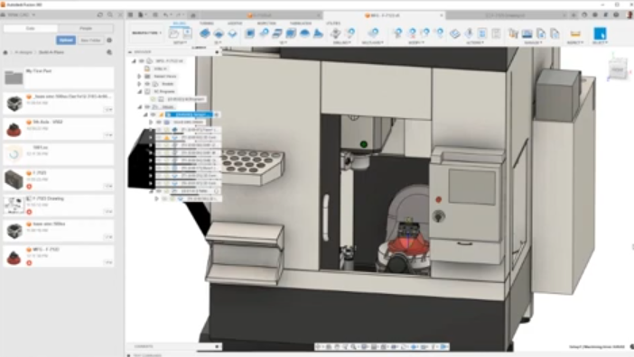
The released CAD model is imported or opened in the CAM environment. The CAM programmer:
Defines the stock (raw material size and shape), sets up the coordinate system (work offsets and origin), selects the target machine (e.g., 3-axis mill, lathe, 5-axis machining center), and chooses or creates relevant tools in the tool library.
Toolpath creation and optimization
Toolpaths are then generated step by step:
Roughing paths to remove bulk material, rest machining to clean up remaining areas, semi-finishing passes to approach final form, and finishing passes for final dimensions and surface finish. Drilling, tapping, boring, and other hole-making cycles are added as needed.
Paths are refined by adjusting entry and exit moves, stepovers, stepdowns, and linking moves to balance machining time, tool life, and machine stability.
Simulation and verification
Before code is sent to the CNC machine, CAM systems simulate tool motion and material removal. This helps detect:
Collisions between tools, holders, fixtures, and the workpiece, gouging or overcut conditions, undercut regions where material remains, and rapid moves that may exceed machine travel or limits.
Simulation reduces the risk of scrap parts, machine damage, and downtime.
Post-processing and shop floor execution
After verification, the CAM software post-processes the toolpaths to generate NC code for the specific machine controller. Setup documentation, including fixture diagrams, tool lists, and operation summaries, may be exported alongside the code.
The NC program is then transferred to the CNC machine. The machinist sets up tools and fixtures according to the documentation, verifies offsets and parameters, and runs the job, often starting with single-block or dry-run modes for safety.
Typical Users and Skills for CAD vs CAM
Although some professionals use both CAD and CAM, distinct skill sets are often associated with each discipline.
CAD-focused roles
Typical CAD users include mechanical design engineers, product designers, industrial designers, and design drafters. Relevant skills include:
3D modeling proficiency in one or more CAD systems, understanding of engineering principles and tolerancing, ability to interpret requirements and convert them into geometry, and familiarity with standards used in drawings and documentation.
CAM-focused roles
Typical CAM users include CAM programmers, CNC machinists, and manufacturing engineers. Relevant skills include:
Knowledge of machining processes and cutting tools, understanding of CNC machine capabilities and limitations, ability to select suitable cutting parameters, and proficiency in CAM software for toolpath generation and post-processing.
Pain Points When CAD and CAM Are Misaligned
When CAD and CAM are not aligned, several issues can impact quality, cost, and lead time.
Incomplete or unsuitable CAD geometry
If CAD models are missing critical details, such as fillets, chamfers, or clear tolerances, CAM programming becomes more difficult. CAM users may need to add or interpret geometry, leading to ambiguity and potential errors. Models that are not manufacturable with available machines or tools may require redesigns, delaying production.
Inconsistent data versions
Using outdated CAD files in CAM results in parts that no longer match the latest design. Version mismatches can cause scrap, rework, and inspection failures. Clear revision control and consistent data management are essential to avoid these complications.
Geometric quality and translation issues
Poorly translated geometry with gaps, overlaps, or misaligned surfaces can cause toolpath algorithms to fail or produce unexpected results. CAM programmers may have to repair geometry manually, which introduces extra work and potential inaccuracies.
Limited communication between design and manufacturing
Insufficient communication between CAD and CAM users may lead to designs that are difficult or time-consuming to machine. For example, extremely tight tolerances, deep narrow pockets, or thin walls may require specialized tooling and multiple setups. Early collaboration reduces these barriers.
Integrated CAD/CAM Solutions vs Separate Systems
Companies may use integrated CAD/CAM platforms or separate specialized tools for each function. Each approach has specific characteristics and trade-offs.
| Aspect | Integrated CAD/CAM | Separate CAD and CAM |
|---|---|---|
| Data Handling | Shared native model, minimal file translation | Import/export required, potential translation steps |
| Change Management | Design changes propagate directly to CAM | Changes must be re-imported and reprogrammed as needed |
| System Flexibility | Tied to a single vendor ecosystem | Freedom to choose best-in-class CAD and CAM individually |
| User Workflow | Single environment for both design and manufacturing planning | Distinct environments; often clear separation of roles |
| Learning Curve | Users may learn one platform that covers both areas | Users specialize in different tools with distinct interfaces |
Applications of CAD and CAM in Industry
CAD and CAM are used across many industries, each with specific requirements but similar underlying workflows.
Mechanical and industrial manufacturing
In general mechanical manufacturing, CAD models describe components ranging from brackets and housings to complex machinery parts. CAM systems generate toolpaths for milling, turning, drilling, and grinding operations to meet dimensional and surface finish requirements.
Automotive and aerospace
Automotive and aerospace applications often involve tight tolerances, complex geometries, and critical performance requirements. CAD is used to define components such as engine parts, structural elements, and aerodynamic surfaces. CAM is used to plan multi-axis machining strategies, manage large tool libraries, and ensure consistent repeatability across batches and locations.
Tooling, molds, and dies
CAD models for molds and dies must reflect shrink allowances, draft angles, and precise parting lines. CAM is essential in this domain for generating 3-axis and 5-axis toolpaths that accurately machine complex cavity surfaces and cores while controlling surface quality and machining time.
Medical devices and implants
In medical applications, CAD models represent implants, surgical instruments, and device components with specific anatomical fit and functional requirements. CAM programs multi-axis operations on biocompatible materials, considering the small features and tight tolerances common in this field.
Criteria for Choosing CAD and CAM Software
Selecting appropriate CAD and CAM tools depends on technical requirements, organizational structure, and existing infrastructure.
Key factors for CAD selection
When evaluating CAD systems, organizations often consider:
Modeling capabilities for the required geometry complexity, assembly handling performance, drawing and documentation features, compatibility with existing data formats, and availability of libraries, templates, and automation tools.
Key factors for CAM selection
When evaluating CAM systems, important considerations include:
Support for required machining processes (milling, turning, mill-turn, multi-axis), reliability and flexibility of toolpath strategies, quality of simulation and verification, availability of machine-specific post-processors, and ease of managing tools, setups, and operations.
Alignment with machines and workflows
Both CAD and CAM tools must integrate smoothly into existing workflows. This includes:
Compatibility with PLM or data management systems, support for the installed base of CNC machines, and alignment with skill sets of designers, programmers, and machinists. Proper alignment reduces ramp-up time and improves consistency.
How CAD and CAM Improve Manufacturing Efficiency
When used effectively, CAD and CAM contribute to efficient, repeatable manufacturing with controlled quality.
Reduced manual drafting and programming
Digital CAD models eliminate the need for repeated manual drafting and reduce ambiguity in drawings. CAM automates much of the NC programming, replacing manual coding with verified toolpaths and structured operations. This reduces human error and speeds up preparation for production.
Reusability of designs and processes
CAD allows reuse of existing components, assemblies, and design templates. CAM enables reuse of machining templates, tooling configurations, and process parameters. Together, they support standardized approaches for families of parts and repeated orders, improving consistency and reducing setup time.
Accuracy and traceability
CAD models define exact geometry, while CAM uses those models to drive precise machining. Digital records of design versions, toolpaths, and NC programs provide traceability from design through manufacturing. This traceability supports quality management and documentation requirements.
Relationship Between CAD, CAM, and Other Systems
Although this article focuses on CAD and CAM, they operate alongside other digital systems in a broader engineering environment.
CAD, CAE, and PLM
CAD models are often used as the basis for CAE (Computer-Aided Engineering) analysis, including structural, thermal, and fluid simulations. Results from CAE may lead to design changes in CAD, which then propagate downstream to CAM.
PLM (Product Lifecycle Management) systems manage versions, approvals, and access to CAD data, ensuring that the right models are used in both analysis and manufacturing stages.
CAM, MES, and CNC control
CAM output interacts with MES (Manufacturing Execution Systems) that schedule and track production on the shop floor. CNC control systems execute the NC programs generated by CAM, and feedback from the machines can inform adjustments to toolpaths or parameters in future runs.
Summary: Key Differences Between CAD and CAM
CAD is primarily concerned with defining what a product or component is: its geometry, dimensions, and functional relationships. CAM is primarily concerned with how that product will be manufactured: which tools, strategies, and machine motions will be used to transform raw material into the desired shape.
CAD serves designers and engineers who build digital models and documentation, while CAM serves programmers and machinists who translate designs into manufacturable operations. Both systems are most effective when tightly integrated, with accurate data transfer, good communication across roles, and clear alignment with machine capabilities and production goals.
FAQ: CAD vs CAM
What is the main difference between CAD and CAM?
The main difference is their purpose:
CAD focuses on design — creating and refining digital models.
CAM focuses on manufacturing — converting those designs into machine instructions for production.
In short, CAD defines what to make, while CAM defines how to make it.
Can CAD and CAM be used together?
Yes. CAD and CAM are often used together in a seamless workflow. A design created in CAD software can be directly imported into CAM software to generate toolpaths and machining instructions, improving efficiency and reducing errors.
Do CAD and CAM require different software?
Traditionally, CAD and CAM were separate tools. Today, many modern platforms integrate both functions into a single solution, commonly referred to as CAD/CAM software, such as for CNC machining, mold making, and product design.
Who uses CAD and CAM software?
CAD is mainly used by product designers, engineers, and draftsmen.
CAM is typically used by CNC programmers, machinists, and manufacturing engineers.
Both are essential in industries such as automotive, aerospace, machine tools, metalworking, and industrial manufacturing.
What are examples of CAD and CAM software?
Common examples include:
CAD software: AutoCAD, SolidWorks, CATIA, Fusion 360
CAM software: Mastercam, PowerMill, SolidCAM, Edgecam
Many platforms, such as Fusion 360, combine both CAD and CAM capabilities.
