
Aluminum machining combines the material advantages of aluminum with subtractive manufacturing technologies such as CNC milling and turning. This guide explains key processes, machinable alloys, dimensional capabilities, surface finishes, design guidelines, and cost structure for aluminum components across industries such as aerospace, automotive, electronics, and industrial equipment.
Fundamentals of Aluminum Machining
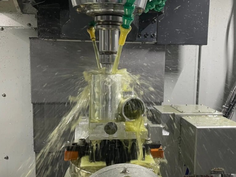
Aluminum machining is the controlled removal of material from aluminum stock (billets, plates, bars, or castings) using cutting tools. Because aluminum is relatively soft, has low density, and exhibits good thermal conductivity, it supports high cutting speeds and efficient chip formation when tooling and parameters are selected correctly.
Machining is used for prototyping, low-volume custom parts, and high-volume production where accurate features, tight tolerances, and good surface finish are required. It is also applied as a secondary operation on cast, extruded, or additively manufactured aluminum components to achieve precision critical surfaces.
Common Aluminum Alloys Used in Machining
Choice of aluminum alloy affects machinability, strength, corrosion resistance, and achievable tolerances. The most common wrought alloys for machining belong to the 2xxx, 5xxx, 6xxx, and 7xxx series, and several casting alloys are also widely used.
| Alloy | Temper | Typical Uses in Machining | Approx. UTS (MPa) | Relative Machinability |
|---|---|---|---|---|
| 6061 | T6 | General structural parts, fixtures, housings | 290–320 | Good |
| 6082 | T6 | Industrial components, frames, high-strength profiles | 290–340 | Good |
| 7075 | T6/T651 | Aerospace, high-stress components, tooling | 510–570 | Moderate |
| 2024 | T3/T351 | Aerospace, stressed structural members | 430–480 | Moderate |
| 5083 | O/H111 | Marine components, welded fabrications | 270–330 | Fair |
| 5052 | H32/H34 | Sheet-metal based parts, enclosures with machining features | 215–260 | Good |
| 6082 cast plate (rolled tooling plate) | T651 | Tooling, jigs, precision plates | 280–320 | Very good |
| A380 (casting) | As-cast / heat-treated | Die cast housings, brackets, post-machined surfaces | 300–350 | Moderate |
Machinability depends on alloy composition, temper, and product form. Free-machining alloys may contain lead or bismuth, but these are less common in high-performance applications due to environmental and regulatory considerations.
Key Aluminum Machining Processes
Aluminum can be machined by multiple subtractive processes. Process selection depends on geometry, precision, surface requirements, and production volume.
CNC Milling
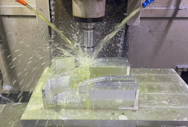
CNC milling uses rotating tools and multi-axis motion to remove material from plates, blocks, or near-net-shape blanks. Due to aluminum’s favorable chip formation and thermal behavior, milling can be performed at high cutting speeds.
- Typical operations: face milling, contouring, pocketing, drilling, tapping, boring
- Multi-axis capabilities: 3-axis, 4-axis, and 5-axis setups for complex geometries
- Applications: housings, brackets, manifolds, heat sinks, structural components
High spindle speeds (often 10,000–30,000 rpm on production centers), appropriate tool coatings (TiB2, TiAlN, DLC), and optimized coolant delivery help maximize material removal rates while controlling heat and extending tool life.
CNC Turning
CNC turning is used for rotational parts such as shafts, bushings, rings, and cylindrical housings. Aluminum’s low cutting force requirements allow efficient turning on lathes with high spindle speeds and rapid cycle times.
Typical turning operations include:
- External turning and facing
- Boring and internal profiling
- Grooving and threading (metric, imperial, special profiles)
Turning can be combined with live tooling and sub-spindles for complete machining in a single setup, reducing runout and cumulative tolerance stack-up.
Drilling, Boring, and Tapping
Aluminum machining frequently involves numerous holes, threads, and precision bores. Efficient chip evacuation and correct lubrication are crucial to avoid chip welding and tool breakage.
Considerations include:
Drilling: Use high-helix drills with polished flutes for optimal chip evacuation. Peck drilling is recommended for deep holes with length-to-diameter ratios above approximately 10:1.
Boring: Boring operations improve hole position, straightness, and diameter accuracy beyond what drilling alone can achieve, especially for bearing fits and precision dowel locations.
Tapping: Form taps (roll taps) are often preferred for aluminum due to stronger threads and absence of chips. Cutting taps remain common for blind holes with coolant limitations or certain thread geometries.
High-Speed Machining of Aluminum
High-speed machining (HSM) of aluminum uses elevated spindle speeds, low radial engagement, and high feed rates to maintain constant chip load and stable cutting conditions. The goal is to maximize metal removal rate while preserving dimensional accuracy and surface integrity.
HSM is particularly effective for:
Thin walls where lower cutting forces reduce deflection, large pocketing and cavity milling, die and mold applications, and aerospace structural parts where material removal from billets or plates is extensive.
Secondary and Support Processes
Beyond primary machining, aluminum components often require additional operations:
Deburring: Manual, mechanical, or thermal methods remove sharp edges and residual burrs from holes, slots, and intersecting features. This improves assembly and reduces risk of contamination in hydraulic or pneumatic systems.
Reaming and honing: These operations refine hole geometry and surface finish for pins, bearings, or precision alignment features.
Parting, cutting, and sawing: Used to cut raw stock to length before machining or to separate multiple parts from a common blank.
Dimensional Capabilities and Tolerances
Aluminum machining supports tight tolerances when machines are rigid, properly calibrated, and thermal expansion is controlled. The achievable tolerances depend on feature type, part size, and production conditions.
Typical Tolerance Ranges
For many commercial CNC aluminum components:
- General dimensional tolerance: ±0.05 mm (±0.002 in) or better
- Precision features on small parts: ±0.01–0.02 mm (±0.0004–0.0008 in)
- Bored holes and reamed holes: IT7–IT8 tolerance grades or finer
Larger parts or long features are more sensitive to thermal expansion and machine travel accuracy. In such cases, tolerances of ±0.1–0.2 mm may be specified unless critical interfaces require tighter values.
Form and Position Tolerances
Geometric tolerances such as flatness, parallelism, perpendicularity, and true position are commonly applied to aluminum parts. These tolerances are governed by fixturing, machining sequence, and part stiffness.
Practical guidance includes:
Apply flatness and parallelism where mating surfaces or sealing faces are involved.
Use true position and concentricity tolerances for holes and shafts that must align with bearings, dowels, or rotational axes.
Specify geometric tolerances only where functionally necessary to avoid unnecessary machining time and cost.
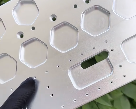
Surface Finish Capabilities
Surface roughness (Ra) achievable in aluminum machining depends on cutting tools, machine rigidity, and finishing strategy.
| Operation / Strategy | Typical Ra (µm) | Common Applications |
|---|---|---|
| Rough milling | 3.2–6.3 | Non-critical surfaces, pre-finishing stock removal |
| Standard finish milling | 1.6–3.2 | General external surfaces, internal cavities |
| Fine finish milling / turning | 0.8–1.6 | Visible surfaces, improved sealing areas |
| Precision turning with optimized tooling | 0.4–0.8 | Shafts, bearing journals |
| Reaming / fine boring | 0.4–1.6 | Precision bores, alignment holes |
Secondary finishing processes such as polishing, micro-finishing, or lapping can further improve surface quality when required by optical, sealing, or sliding contact applications.
Surface Treatments and Finishing Options
Aluminum surfaces are often treated after machining to improve corrosion resistance, wear resistance, or appearance, or to prepare for bonding and painting. Machining marks, burrs, and contaminants must be removed to ensure uniform treatment.
Anodizing
Anodizing is an electrochemical process that grows a controlled oxide layer on aluminum surfaces. It improves corrosion resistance and can provide decorative coloration.
Main variants:
Type II (sulfuric acid anodizing): Typical oxide thickness 5–25 µm. Supports a wide range of colors and is common for consumer products and general industrial components.
Type III (hard anodizing): Typical thickness 25–50 µm or more. Provides increased wear resistance and better protection in aggressive environments, often used for sliding or abrasive contact surfaces.
Dimensional growth: Anodizing adds thickness to surfaces; about half the coating thickness is growth above the original surface and half penetrates into the substrate. Dimensional changes must be considered for tight tolerances and fitted parts.
Conversion Coatings
Chemical conversion coatings (e.g., chromate-free alternatives) provide thin, conductive, and corrosion-resistant layers. They are used as pre-treatments for painting, powder coating, or adhesive bonding, and for electrical grounding where anodizing is unsuitable.
Painting and Powder Coating
Painting and powder coating offer color, UV protection, and additional corrosion resistance. Aluminum surfaces must be properly prepared with cleaning, degreasing, and often conversion coating before application.
Mechanical Finishing
Mechanical finishing methods include:
Bead blasting: Creates a uniform matte finish, removes minor machining marks, and provides a consistent texture prior to anodizing or painting.
Vibratory finishing and tumbling: Smooth edges and surfaces of small components in bulk. Often used for fasteners, brackets, and small fittings.
Design Guidelines for Machined Aluminum Parts
Design strongly affects manufacturability, cost, and performance of aluminum components. Effective design leverages material properties and machining capabilities while avoiding unnecessary complexity.
Wall Thickness and Stiffness
Aluminum’s relatively low modulus of elasticity (about 70 GPa) makes thin walls prone to deflection and chatter during machining. As a general guideline:
For walls being milled from solid, thicknesses of about 0.8–1.0 mm at minimum are workable for small features, but more robust walls of 1.5–3.0 mm are preferred for structural stability and cost efficiency.
Ribs can be incorporated to stiffen thin walls without significantly increasing mass, balancing weight and rigidity.
Corner Radii and Internal Features
Machining internal sharp corners is constrained by tool diameter. Incorporating corner radii aligned with available end mill sizes reduces machining time and improves tool life.
Guidelines:
Internal pocket corners: Use radii equal to or slightly larger than cutter radius. For example, with a 6 mm end mill, internal radii of 3–3.5 mm are practical.
Deep pockets: Employ step-down strategies and corner relief to minimize tool deflection, especially when depth exceeds about 3 times the cutter diameter.
Hole Design and Threading
Hole geometry should consider standard drill sizes, depth-to-diameter ratios, and thread engagement.
Through-holes are generally more economical than blind holes due to easier chip evacuation.
For tapped holes, a thread engagement length of about 1–1.5 times nominal thread diameter is typically sufficient in aluminum. Excessive depth increases machining time with diminishing returns in strength.
Tolerances and GD&T Strategy
Over-constraining components with overly tight tolerances increases machining and inspection time. It is practical to consider:
Applying tight tolerances only on functional interfaces.
Allowing looser general tolerances on non-critical surfaces and cosmetic features.
Defining clear datum structures to control critical relationships between features.
Fixturing and Accessibility
Parts should be designed with fixturing and tool access in mind:
Avoid deep, narrow features that restrict tool access without necessity.
Include gripping surfaces where possible to allow stable clamping without interfering with functional areas.
Minimize the number of setups by grouping critical features on accessible faces.
Capabilities by Machine Type and Axis Configuration
Aluminum machining capabilities vary with machine architecture and axis configuration. Selecting the appropriate machine type balances flexibility, precision, and cost per part.
3-Axis CNC Machining
3-axis milling centers move in X, Y, and Z directions and are suitable for the majority of prismatic parts with features accessible from a limited number of orientations.
Characteristics:
Efficient for flat parts, plates, housings with features on top and side faces.
Requires multiple setups for features on opposing or angled faces.
Cost-effective for medium complexity parts and moderate batch sizes.
4-Axis and 5-Axis CNC Machining
4-axis machines add a rotary axis, while 5-axis machines provide two rotary axes, enabling more complex tool orientations and part manipulation.
Benefits:
Single-setup machining for multiple faces, reducing cumulative errors.
Ability to machine undercuts, compound angles, and complex contours.
Improved surface quality on sculpted geometries due to optimal tool orientation.
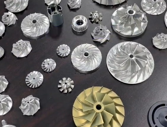
These configurations are commonly used for aerospace components, impellers, turbine blades, and complex housings where feature relationships are critical.
Multi-Tasking Machines and Mill-Turn Centers
Mill-turn centers combine turning and milling operations, often with multiple spindles and tool turrets. They are suited to aluminum parts that are primarily rotational but include prismatic or cross-drilled features.
Advantages include:
Reduced handling and setup time.
Improved concentricity between turned and milled features.
Shortened lead times for complex, high-precision parts.
Material Removal Rates and Productivity Considerations
Aluminum supports high material removal rates (MRR) due to its low hardness and good thermal conductivity. Productivity depends on cutting parameters, toolpath strategies, and machine rigidity.
Typical Cutting Parameters
Exact parameters are determined by specific alloy, tool type, and machine, but indicative ranges include:
Milling tool speeds: Commonly 6,000–24,000 rpm for carbide tools on production machines. Higher speeds are possible with high-speed spindles.
Feed per tooth (fz): Often in the range of 0.05–0.25 mm/tooth depending on tool diameter and stability.
Depth of cut and width of cut: Roughing operations favor higher axial depths (e.g., up to 1–2 times tool diameter) with moderate radial engagement; finishing uses shallow depths and lower engagement for improved surface finish.
Chip Evacuation and Lubrication
Effective chip evacuation is critical in aluminum machining to prevent chip re-cutting and built-up edge formation on tools.
Common approaches:
Flood coolant to remove heat and flush chips.
High-pressure through-tool coolant for deep drilling and pocketing.
Minimum quantity lubrication (MQL) or mist for high-speed operations where flood coolant is undesirable.
Cost Structure in Aluminum Machining
Cost analysis for machined aluminum parts involves both material and manufacturing components. Understanding primary cost drivers helps in design decisions and supplier selection.
Calculate Your Aluminum Machining Cost
3/4/5-axis · mainly 6061/7075
※ Real prices vary greatly depending on region, shop rate, tool consumption, lead time, certifications, etc.
※ For accurate pricing, please send 3D files + detailed requirements to machining shops
Material Costs
Material cost is influenced by alloy type, stock form, and buy-to-fly ratio (mass of raw stock vs. mass of finished part).
Key considerations:
Common alloys such as 6061-T6 are generally more economical and widely stocked than specialty aerospace grades.
Using standard sizes of plate, bar, or extrusion minimizes waste and sourcing time.
Heavy material removal from solid billets increases both raw material and machining time; near-net-shape extrusions or castings can reduce overall cost when volumes justify tooling.
Machining Time and Machine Hour Rates
Machining time is typically the largest controllable cost component. It depends on:
Setup time: Fixture design, program loading, first article inspection.
Cycle time: Actual cutting time, tool changes, and machine movements per part.
Handling time: Loading and unloading parts, in-process inspection.
Machine hour rate reflects equipment value, maintenance, and overhead. As a simplified view, high-end 5-axis centers have higher hourly rates than standard 3-axis mills, but can reduce cycle time and setups significantly.
Tooling and Consumables
Tooling costs include cutting tools, holders, and fixtures. For aluminum, carbide end mills, drills, and inserts are common, often with coatings tailored for non-ferrous materials.
Tooling-related factors:
Complex parts may require specialized form tools or custom fixtures, increasing upfront cost but reducing cycle time in higher volumes.
Tool life in aluminum is generally favorable when parameters are optimized, but inadequate chip evacuation or improper coating selection can shorten life and increase cost.
Finishing and Post-Processing Costs
Surface treatments (anodizing, coating, conversion) add per-part or per-batch costs, including masking, racking, and inspection. Each additional process step adds handling and lead time.
When possible, grouping parts for batch finishing and standardizing surface requirements can reduce per-part finishing cost.
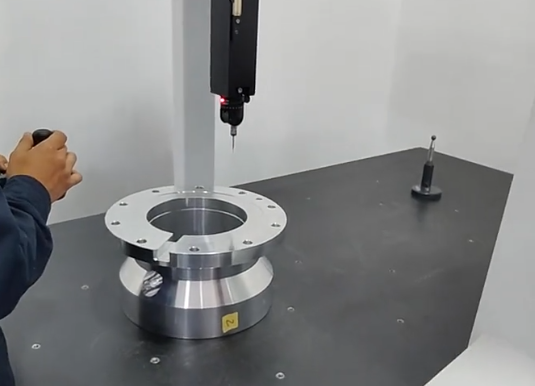
Inspection and Quality Assurance
Inspection costs increase with tolerance tightness, part complexity, and required documentation. Use of CMM (coordinate measuring machines), optical scanners, and specialized gauges involves both equipment and labor.
When designing parts, balancing functional requirements with pragmatic tolerance levels helps control both machining and inspection costs.
Issues and Practical Considerations in Aluminum Machining
While aluminum is generally considered a machinable material, several issues commonly arise in production environments.
Built-Up Edge and Surface Defects
Aluminum’s tendency to adhere to cutting edges can cause built-up edge, leading to poor surface finish and dimensional variation. Correct tool geometry, appropriate coatings, and adequate lubrication are necessary to mitigate this effect.
Distortion After Machining
Residual stresses in rolled plate or extrusions can cause parts to warp when significant material is removed. Stress-relieved, cast, or tooling plate can reduce distortion. Machining strategies that remove material symmetrically and intermediate stress-relief cycles can further improve stability.
Burr Formation
Aluminum tends to form burrs on exit edges of cuts, especially on drilled and milled features. Control of burr formation requires optimized cutting parameters, sharp tools, and dedicated deburring processes where necessary.
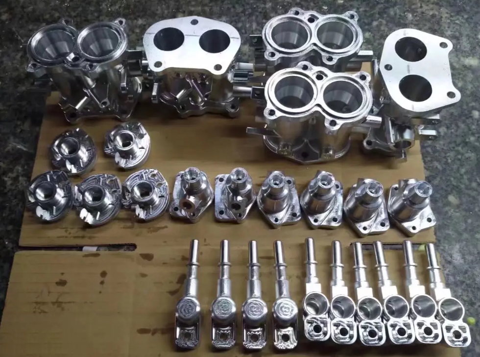
Industry Applications of Machined Aluminum Parts
Machined aluminum components are used across many sectors due to the combination of strength, weight, and corrosion resistance.
Aerospace and Defense
Aluminum is extensively used for structural components, brackets, housings, and mounts. High-strength alloys such as 7075 and 2024 are common where specific stiffness and fatigue performance are important.
Automotive and Transportation
In vehicles and rail systems, machined aluminum parts include suspension components, brackets, gearbox housings, and thermal management components. The balance of weight reduction and manufacturing cost is central in this sector.
Electronics and Thermal Management
Aluminum’s thermal conductivity makes it suitable for heat sinks, electronic housings, and cooling plates. Machined fins, channels, and mounting surfaces are used to manage heat dissipation in power electronics and computing equipment.
Industrial Equipment and Automation
Aluminum is used in machine frames, automation components, end-of-arm tooling, fixtures, and jigs. The material’s ease of machining supports customization and rapid iteration of mechanical designs.
How to Estimate and Control Aluminum Machining Costs
Cost estimation for aluminum machining integrates design complexity, material selection, and process planning. Several practical approaches can help manage cost while maintaining performance.
Design for Manufacturability (DFM)
Involving manufacturing expertise early in design allows identification of features that drive cost disproportionately. Adjusting wall thicknesses, tolerances, and surface finish requirements can significantly reduce machining time and scrap risk.
Batch Size and Setup Optimization
Larger batch sizes distribute setup costs over more parts, reducing cost per unit. Modular fixturing and standardized setups also help in managing small and medium batch production efficiently.
Supplier Capabilities and Equipment Match
Aligning part requirements with supplier capabilities is important:
High-precision, multi-axis parts should be directed to shops with appropriate 4-axis/5-axis and metrology equipment.
Simpler components may be more economical at facilities optimized for high-volume 3-axis machining and turning.
Conclusion
Aluminum machining is a versatile and mature manufacturing approach capable of producing precise, lightweight, and corrosion-resistant components for a wide range of industries. By understanding material behavior, machining processes, tolerance capabilities, surface treatments, and cost drivers, engineers and buyers can design and source aluminum parts that meet functional requirements while controlling lead time and cost.
FAQ
What is aluminum machining?
Aluminum machining is a subtractive manufacturing process that removes material from aluminum stock using CNC milling, turning, drilling, or tapping to produce precise components.
Why is aluminum widely used in machining?
Aluminum is lightweight, corrosion-resistant, highly machinable, and offers excellent strength-to-weight ratio, making it ideal for a wide range of industrial applications.
What aluminum alloys are best for machining?
Popular machinable aluminum alloys include 6061, 7075, 5052, and 2024, each offering different balances of strength, corrosion resistance, and machinability.
How does aluminum machining compare to steel machining?
Aluminum machining is generally faster, requires less cutting force, and reduces tool wear compared to steel, resulting in lower production costs.
