
What Is an Air Manifold Block
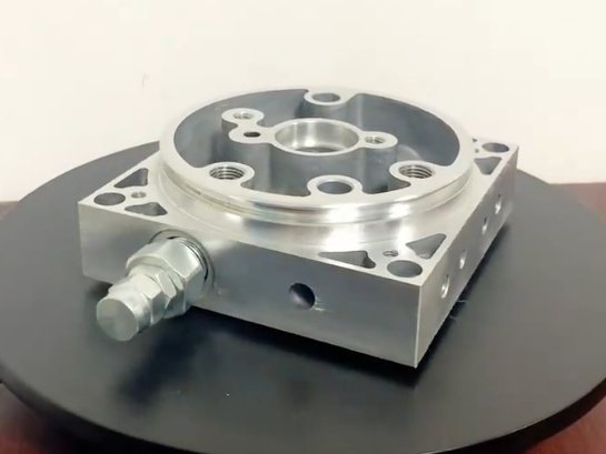
An air manifold block is a compact component used to distribute compressed air from one or more supply inlets to multiple outlets. It acts as a central node in a pneumatic system, routing air to valves, cylinders, tools, or other devices while minimizing hose runs and connection points.
In its simplest form, an air manifold block is a machined metal or plastic block with interconnected internal passages and threaded ports. It consolidates air distribution into a single, organized component, simplifying design, assembly, and maintenance of pneumatic circuits.
Core Functions and Applications
The air manifold block serves several fundamental functions in compressed air and pneumatic automation environments:
- Distribute compressed air from one supply to multiple circuits
- Provide organized mounting for valves, pressure regulators, and sensors
- Reduce the number of separate fittings, tees, and hoses
- Provide isolation points via integrated shut-off or plug ports
- Support modular expansion of pneumatic systems
Typical applications include industrial automation, machine tools, packaging lines, robotics, material handling systems, process control equipment, test rigs, and general compressed air distribution panels.
Key Design Types of Air Manifold Blocks
Air manifold blocks are available in several design configurations that address different system layouts and space constraints.
Inline and Bar Manifolds
Inline or bar manifolds are elongated blocks with a main supply channel running along the length of the body. Outlets are arranged in a linear pattern on one or multiple faces. They are used for:
- Supplying several valves or cylinders arranged in a row
- Mounting along machine frames or panels
- Simple, compact air distribution bars in cabinets
Central, Header, and Distribution Manifolds
Central or header manifolds are typically block-shaped or plate-like components used as main distribution hubs from a primary compressor line. They may incorporate ports on multiple faces to feed different machine sections or branch circuits.
Valve Manifold Blocks
Valve manifold blocks are designed specifically to mount multiple directional control valves in a shared block. These systems commonly feature:
Standardized valve interfaces (e.g., ISO, NAMUR, or proprietary patterns), shared supply and exhaust galleries, and integrated electrical or fieldbus interfaces via separate modules. They are widely used in automation islands to reduce tubing and simplify wiring.
Modular Manifolds
Modular manifolds consist of stackable or connectable segments which can be added or removed to match the number of stations required. Each segment may contain its own valve, regulator, flow control, or sensor, with O-ring seals between modules creating continuous supply and exhaust passages.
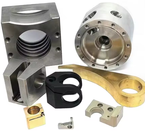
Materials and Surface Treatments
The choice of manifold material affects strength, corrosion resistance, cleanliness, weight, and compatibility with the working environment.
| Material | Typical Pressure Range | Key Properties | Typical Uses |
|---|---|---|---|
| Aluminum (e.g., 6061, 6082) | Up to approx. 10–16 bar (145–232 psi) and higher with proper design | Lightweight, good machinability, moderate corrosion resistance, suitable for most industrial compressed air | General automation, machine building, valve manifolds |
| Carbon Steel | High pressure capability, often above 20 bar (290 psi) depending on design | High strength, robust, may require coatings to prevent corrosion | Heavy-duty industry, high-pressure circuits, harsh mechanical environments |
| Stainless Steel (e.g., 304, 316) | Similar or higher than carbon steel for many designs | Excellent corrosion resistance, suitable for washdown and some aggressive media | Food and beverage, chemical, pharmaceutical, outdoor installations |
| Brass | Generally up to approx. 10–16 bar (145–232 psi) | Good corrosion resistance, good machinability, stable in many environments | General industrial use, compressed air, some fluid applications |
| Engineering Plastics (e.g., PA, PBT, PET) | Typically up to approx. 8–10 bar (116–145 psi), depending on design | Lightweight, corrosion free, electrical insulation, limited temperature range | Compact manifolds for light-duty automation, electronics, laboratory systems |
Surface treatments such as anodizing (for aluminum), zinc plating, nickel plating, or passivation (for stainless steel) can improve corrosion resistance and wear performance. The choice should align with humidity, possible chemical contact, and cleaning procedures in the installation environment.
Port Types, Sizes, and Thread Standards
Port type and size are critical design parameters because they determine compatibility with fittings, hoses, and valves, as well as the achievable flow rate.
Threaded Port Standards
Typical port threading standards include:
- NPT (National Pipe Taper): common in North America, taper thread sealing
- G / BSPP (British Standard Pipe Parallel): common in Europe and many global markets, used with sealing washers or O-rings
- BSPT (British Standard Pipe Taper): taper thread sealing used regionally
- Metric threads: often combined with O-ring face or form-fit sealing
Manufacturers usually clearly specify the thread standard; mixing incompatible thread forms can cause leaks, damage, or unsafe connections.
Port Size and Flow Considerations
Ports are typically designated by nominal size, such as 1/8", 1/4", 3/8", 1/2" for NPT or BSP, or by metric size for tubing connections. Larger ports allow higher flow with lower pressure drop but require more space. Port sizing must be evaluated together with expected flow and line length.
Tubing and Push-In Fittings
Many air manifold blocks are designed to work with push-in fittings and plastic tubing (e.g., 4 mm, 6 mm, 8 mm, 10 mm, 12 mm). The manifold body can have threaded ports that accept fittings, or integrated push-in connections. Selection should consider tubing outer diameter, operating pressure, and bending radius requirements.
Flow Capacity and Pressure Drop
Flow capacity is a central performance characteristic of an air manifold block. It defines the amount of air (usually in NL/min, L/min, or SCFM) that can flow through the manifold with a given pressure drop.
Key considerations:
Internal Passage Dimensions: The size and layout of internal channels affect turbulence and pressure loss. Straight, oversized passages typically yield lower pressure drop than narrow or sharply bent channels.
Port Size and Quantity: The main supply port must be large enough to feed all outlets simultaneously if required. Outlet size should be appropriate for each consuming device.
Operating Pressure: Required flow at working pressure must be evaluated based on all connected devices. Undersized manifolds can cause slow cylinder actuation or inadequate torque in pneumatic tools.
Manufacturers often provide flow curves or Kv/Cv values for manifolds. Where this data is available, it should be used during system design to verify that pressure and flow at the point of use meet device specifications.
Sealing Technologies and Leak Prevention
Reliable sealing is essential for efficient compressed air distribution. Leaks increase energy consumption, reduce system performance, and raise maintenance workload.
Common sealing methods include:
Thread Sealants and Tapes: Used on taper threads such as NPT and BSPT. Proper application prevents leaks and allows disassembly. Over-application should be avoided to prevent contamination of internal passages.
O-Ring Boss and Face Seals: Many aluminum and stainless manifold blocks use O-ring grooves around ports or at interface surfaces. These provide repeatable, robust sealing and are common in modular and valve manifold systems.
Gaskets Between Modules: Modular manifold segments often rely on precision-machined faces and elastomeric gaskets or seals between blocks to create continuous galleries.
To reduce leaks, threads should not be over-torqued, sealing surfaces must be clean and undamaged, and compatible seal materials should be selected relative to temperature and media.
Mounting and Integration in Pneumatic Systems
Mounting configuration affects accessibility, serviceability, and resistance to vibration.
Typical mounting arrangements:
Panel Mounting: Manifold blocks attached to control panels or inside enclosures. This is common for distribution manifolds feeding downstream machines. Care must be taken to allow access to all ports.
Machine Frame Mounting: Manifolds mounted on structural elements close to actuators to minimize tubing lengths. This can reduce response time and pressure drops.
DIN Rail or Bracket Mounting: Smaller manifolds and valve manifolds may be mounted via standardized brackets or DIN rail adapters to simplify integration in control cabinets.
In addition to mechanical mounting, integration requires:
Correct orientation of supply and exhaust ports
Provision for isolation valves and filters upstream
Clear labelling of outlets to match circuit documentation
Sufficient clearance for tools to tighten or remove fittings
Selection Criteria for an Air Manifold Block
Selecting an appropriate air manifold block involves balancing performance, compatibility, and installation constraints. The following criteria are essential in most design situations.
Operating Pressure and Safety Margin
The manifold’s maximum working pressure must exceed the system’s maximum operating pressure, including any possible surges. A safety factor is typically applied according to company standards or relevant directives. Proof and burst pressures supplied by manufacturers give additional insight into safety margins.
Flow Requirements and Port Configuration
Required flow for each outlet and the total manifold flow must be known or estimated. Manifold configuration should match this by selecting appropriate port sizes, number of outlets, and internal passage dimensions. For multiple high-consumption devices, a larger supply port or dual-supply configuration may be required.
Material Compatibility and Environment
Environment and media define acceptable material choices:
Corrosive or washdown environments favor stainless steel or specialized coatings
Cleanroom or hygienic applications may require stainless steel with smooth surfaces and compatible sealing materials
Outdoor installations must withstand humidity, UV, and temperature fluctuations
Weight-sensitive applications (for example robotics) may benefit from aluminum or engineering plastics
Temperature Range
The manifold and its seals must withstand minimum and maximum ambient and media temperatures. Both low temperatures (risk of brittleness or condensation) and high temperatures (risk of seal degradation) must be considered. Manufacturer data typically lists permissible temperature ranges for the assembled manifold.
Installation Space and Accessibility
Available installation space determines manifold shape, number of faces with ports, and orientation. Accessibility for maintenance is also important. If fittings cannot be easily reached, leak checks and component replacement become more complicated.
Compatibility with Valves and Accessories
For valve manifolds, compatibility with valve series and communication options is essential. Mounting interfaces, gasket patterns, and electrical connectors must match. For distribution manifolds, compatibility with existing fitting thread types and tubing sizes reduces the need for adapters.
Cost and Total System Impact
While manifold purchase price is important, total system cost should be evaluated. A manifold that reduces fittings, simplifies assembly, and minimizes leaks can improve overall cost effectiveness. In addition, standardizing on a manifold family can reduce spare part inventory.
Typical Issues in Manifold Applications
Several recurring issues can appear when air manifold blocks are specified or implemented without adequate consideration.
Undersized Flow Paths: If internal passages are too small, pressure drop increases and actuators may move slowly or inconsistently, especially during simultaneous operation of multiple outlets.
Incompatible Thread Standards: Mixing NPT and BSP threads can lead to leaks or mechanical damage. Misinterpretation of nominal sizes is a common issue when components from different markets are combined.
Leakage at Module Interfaces: For modular valve manifolds, incorrect assembly torque or damaged seals can cause internal or external leakage, affecting performance of several valves at once.
Limited Access for Maintenance: Poorly positioned manifolds make leak detection, fitting replacement, and reconfiguration difficult, increasing downtime when modifications are needed.
Installation Guidelines and Best Practices
Proper installation helps ensure long-term reliability and optimized flow performance.
Pre-Installation Checks:
Verify manifold type, port sizes, and thread standards against the design documentation. Inspect machined surfaces, ports, and threads for contamination or damage. Confirm that sealing elements (O-rings, gaskets) are present and undamaged.
Mounting:
Secure the manifold on a stable, rigid base using mounting holes or brackets. Avoid stressing the manifold body by misaligned fasteners or bending forces from heavy piping. Where necessary, support external pipes and hoses independently.
Connection of Fittings and Tubing:
Use appropriate thread sealant for taper threads, avoiding contamination of internal flow paths. Tighten fittings to recommended torque values. Use correct tubing outer diameter and ensure clean, square cuts before insertion into push-in fittings.
System Commissioning:
Pressurize the system gradually and check all joints for leaks using approved methods. Verify pressure at outlets and observe actuator performance. If necessary, adjust supply pressure or re-evaluate manifold sizing.
Maintenance, Inspection, and Troubleshooting
Regular inspection helps maintain efficiency and prevent unplanned downtime in pneumatic systems that use manifold blocks.
Routine Inspection Tasks:
Check for audible leaks around fittings and manifold joints
Inspect tubing for signs of wear, kinks, or abrasion
Verify that mounting hardware remains tight and that no cracks are visible in the manifold body
Scheduled Maintenance:
Re-torque critical fittings if recommended by manufacturer guidelines
Clean external surfaces to prevent buildup that could hide leaks
Replace worn or damaged seal elements during planned shutdowns
Troubleshooting Common Issues:
Low Pressure at Actuator: Confirm main line pressure, check for restrictions in filters or regulators, and inspect manifold ports and internal pathways for contamination or narrowing. In applications with high simultaneous demand, evaluate whether manifold sizing is sufficient.
Intermittent Operation: Look for loose fittings, fluctuating supply pressure, or obstruction in shared galleries of valve manifolds.
Localized Leakage: Identify specific leak points using soapy solution or other leak detection tools, then re-seat or replace fittings, O-rings, or gaskets as required.
Dimensional and Technical Data Reference
Manufacturers provide detailed technical data that should be consulted during design and selection.
| Parameter | Description | Design Relevance |
|---|---|---|
| Maximum Working Pressure | Highest continuous pressure at which the manifold can safely operate | Must exceed system working pressure with a suitable safety margin |
| Proof and Burst Pressure | Pressure levels used during testing and failure conditions | Indicates safety robustness and margin beyond normal operation |
| Flow Coefficient (Kv or Cv) | Measure of flow capacity through manifold passages | Used to calculate pressure drop and verify flow capability |
| Port Type and Size | Thread standard and nominal dimensions of supply and outlet ports | Determines compatibility with fittings and devices |
| Temperature Range | Minimum and maximum permissible operating temperatures | Ensures seal and material suitability for environment |
| Material and Surface Treatment | Base material and any coatings or treatments applied | Defines corrosion resistance, strength, and cleanliness |
| Number of Stations / Outlets | Total number of usable outlet ports or valve stations | Must match or exceed the number of connected devices |
| Mounting Pattern | Hole positions, sizes, and other interface dimensions | Important for mechanical integration and panel layout |
Standards and Reference Practices
While many air manifold blocks are proprietary designs, they often must work together with components defined by established standards.
Directional valves may follow ISO interface patterns, ensuring compatibility with standardized valve manifold blocks. Threaded ports are usually designed according to national or international pipe and metric standards. Internal cleanliness and quality testing may align with company or industry-specific practices for pneumatic equipment.
Consulting the relevant standards, manufacturer documentation, and in-house engineering guidelines ensures correct integration in the broader pneumatic system.
FAQ About Air Manifold Blocks
What is an air manifold block?
An air manifold block is a component used in pneumatic systems to distribute compressed air from a single inlet to multiple outlets efficiently.
What are air manifold blocks commonly used for?
They are widely used in automation systems, manufacturing equipment, pneumatic control systems, and industrial machinery to supply air to valves, cylinders, and other pneumatic devices.
Are air manifold blocks compatible with different thread standards?
Yes, air manifold blocks can be manufactured with various thread standards such as NPT, BSPP, BSPT, or metric threads.
What materials are air manifold blocks made from?
Air manifold blocks are typically made from aluminum, stainless steel, brass, or engineered plastics, depending on pressure requirements and operating environments.
