
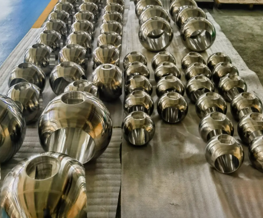
Inconel and related nickel-based superalloys are widely used where high strength, corrosion resistance, and heat resistance are essential. At the same time, they are among the most demanding materials to machine. This guide explains, in a systematic and technical manner, how to machine Inconel effectively, from material understanding to process optimization and quality control.
About Inconel and Its Machinability
Inconel is a family of nickel-chromium-based superalloys designed for high temperature and highly corrosive environments. Their properties that make them desirable in service also make them difficult to machine.
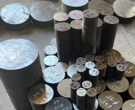
Common Inconel Grades for Machining
The most commonly machined Inconel grades include:
- Inconel 718: Precipitation-hardenable, high strength up to about 700 °C, widely used in aerospace turbine components and power generation.
- Inconel 625: Solid-solution strengthened, excellent corrosion resistance, often used in chemical processing and marine applications.
- Inconel 725: Similar to 625 but age-hardenable, used in oil and gas components.
- Inconel 600/601: Good oxidation resistance, used in furnace components and heat-treat fixtures.
Machinability varies between grades. In general, age-hardened and high-strength grades such as Inconel 718 in hardened condition are the most demanding.
Key Material Properties Affecting Machining
The following properties directly influence cutting behavior and parameter selection:
| Property | Inconel 718 (solution treated & aged) | Inconel 625 (annealed) |
|---|---|---|
| Ni content (wt%) | 50–55 | 58 min |
| Cr content (wt%) | 17–21 | 20–23 |
| Typical tensile strength (MPa) | ~1200–1400 | ~690–830 |
| Yield strength (MPa) | ~1000–1200 | ~275–550 |
| Elongation (%) | ~10–20 | ~30–50 |
| Hardness (HRC / HB) | ~36–44 HRC | ~200 HB |
| Thermal conductivity (W/m·K at 20 °C) | ~11–12 | ~9–11 |
| Coefficient of thermal expansion (µm/m·K) | ~13–15 | ~12–13 |
The combination of low thermal conductivity, high strength at elevated temperatures, and high work hardening tendency leads to elevated cutting forces and rapid tool wear if the process is not carefully controlled.
Why Inconel Is Considered Difficult to Machine
The main technical reasons include:
- Low thermal conductivity: Heat is concentrated at the cutting edge, increasing wear and the risk of thermal cracking.
- High work hardening: The material hardens quickly when deformed, so rubbing or light cuts create a hardened layer that is difficult to cut in the next pass.
- High strength at cutting temperatures: Cutting forces and stresses on the tool remain high even at elevated temperatures.
- Toughness and ductility: Continuous chips, built-up edges, and chip evacuation issues can occur when parameters and tool geometries are not optimized.
General Principles of Machining Inconel
Successful Inconel machining requires rigorous control of cutting conditions and tooling. Several key principles apply across turning, milling, drilling, and other operations.
Maintain Positive Cutting Action
Avoid rubbing and excessive ploughing. Depth of cut and feed should be sufficient to stay below the hardened layer created by previous passes. Very small cuts tend to increase work hardening and reduce tool life.
Manage Heat Effectively
Use abundant cutting fluid, preferably high-pressure coolant directed accurately at the cutting zone. The objective is to evacuate heat with chips and coolant while avoiding steep thermal gradients in the tool that might cause cracking.
Optimize Chip Control
Chip control is crucial to prevent chip re-cutting and to maintain a stable process. Appropriately designed chipbreakers, sufficient feed per revolution/tooth, and the correct combination of speed and depth of cut are needed to generate short, curled chips.
Use Rigid Setups and Stable Machines
Rigidity minimizes vibration and intermittent contact, which are detrimental to tool life and surface integrity. Machine tools should have high stiffness, precise spindle bearings, and minimal backlash. Workholding fixtures and tool overhang must be optimized to reduce deflection.
Tooling Selection for Inconel Machining
The choice of tool material, geometry, and coating strongly influences process reliability and cost.
Tool Materials for Inconel
Common tool materials include:
Carbide tools are widely used for most roughing and semi-finishing operations:
- Submicron grain or fine-grain tungsten carbide with high hot hardness and toughness.
- Grades optimized for high-temperature wear resistance and resistance to notch wear.
Ceramic tools (typically SiAlON or whisker-reinforced ceramics) can be used for high-speed rough turning of certain Inconel alloys in continuous cuts. They offer high hot hardness but lower toughness, so they require stable conditions and are less suitable for interrupted cuts.
CBN (cubic boron nitride) tools are used much less frequently on Inconel than on hardened steels because nickel-based superalloys do not offer a machining environment that fully benefits CBN. However, in some finishing operations at lower speeds, polycrystalline CBN can be applied.
High-speed steel (HSS) tools are generally limited to low-speed operations, manual machining, or specialized forms where carbide is not practical.
Tool Geometry Considerations
Tool geometry significantly affects cutting forces, chip shape, and heat generation. Relevant features include:
- Positive rake angles: Reduce cutting forces and heat, but excessive positive rake may weaken the cutting edge.
- Strong edge preparations: Controlled hone or chamfer to avoid chipping and micro-fracturing of the cutting edge.
- Rounded nose radii: Moderate nose radius improves surface finish and distributes cutting loads, but large radii may cause chatter if rigidity is insufficient.
- Appropriate relief angles: Prevent rubbing while maintaining sufficient support behind the cutting edge.
Coatings for Tools Machining Inconel
Coatings extend tool life by reducing friction and increasing wear resistance. Common coatings include:
- TiAlN or AlTiN: Good high-temperature oxidation resistance and hardness.
- AlCrN: Often used in milling and drilling with improved oxidation resistance.
- Multilayer PVD coatings: Designed to resist abrasive and adhesive wear in nickel alloys.
CVD coatings are less common due to the need for sharper edges and reduced edge rounding; however, certain CVD-coated carbides are successfully used in stable roughing applications.
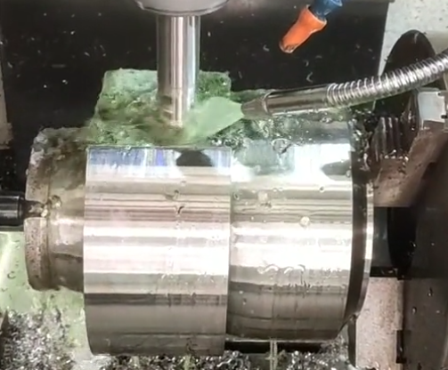
Cutting Parameters for Inconel Turning
Turning is one of the most common operations for Inconel components. Cutting data must be chosen to balance productivity, tool life, and workpiece integrity.
Typical Ranges for Turning Parameters
Exact values depend on grade, hardness, tool material, and machine capability, but the table below presents indicative ranges for carbide tools in Inconel 718 and 625.
| Operation | Cutting speed vc (m/min) | Feed f (mm/rev) | Depth of cut ap (mm) |
|---|---|---|---|
| Rough turning (Inconel 718) | 20–60 | 0.20–0.40 | 1.5–4.0 (depending on rigidity) |
| Semi-finishing (Inconel 718) | 30–70 | 0.10–0.25 | 0.5–2.0 |
| Finishing (Inconel 718) | 40–80 | 0.05–0.15 | 0.2–0.8 |
| Rough turning (Inconel 625) | 40–90 | 0.20–0.45 | 1.5–4.0 |
| Finishing (Inconel 625) | 50–100 | 0.05–0.20 | 0.2–1.0 |
When using ceramic tools for rough turning Inconel 718, cutting speeds may be significantly higher, often in the range of 120–300 m/min or more, but only in continuous cuts and with robust setup.
Depth of Cut Strategy in Turning
Depth of cut should be large enough to cut beneath the work-hardened surface layer from the prior pass, which can extend approximately 0.1–0.3 mm deep depending on conditions. Light skimming cuts with low feed should be avoided whenever possible.
For roughing, a strategy of fewer passes with larger depths of cut generally improves tool life and reduces work hardening, provided that machine power and rigidity are sufficient.
Feed Rate and Surface Integrity
Higher feed rates can assist with chip breaking and reduce heat per unit length of cut, but also increase surface roughness. For finishing operations requiring tight surface finish, typical feeds may be 0.05–0.15 mm/rev, while roughing may use up to 0.40–0.45 mm/rev as long as forces remain acceptable.
Tool Wear Mechanisms in Turning Inconel
Common wear mechanisms include:
- Flank wear: Caused by abrasion, adhesive wear, and high temperatures.
- Crater wear: Occurs on the rake face where chips flow over the tool.
- Notch wear: At the depth of cut line due to work hardening and intermittent contact.
- Chipping and fracture: Due to mechanical shock, interrupted cuts, or inadequate edge preparation.
Monitoring tool wear and replacing inserts before catastrophic failure is important to maintain dimensional accuracy and avoid damage to the workpiece.
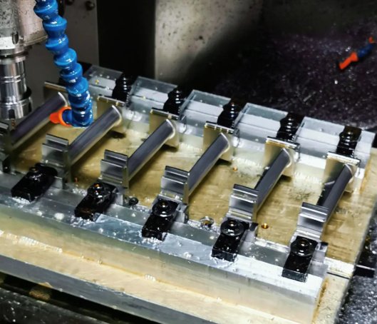
Cutting Parameters for Inconel Milling
Milling operations on Inconel components often involve variable engagement, interrupted cuts, and complex geometries. Proper selection of cutter type, insert geometry, and parameters is essential.
Milling Cutter Selection
Recommended choices include:
- Solid carbide end mills with variable helix for smaller features.
- Indexable insert cutters for larger surfaces and higher material removal rates.
- High-feed milling cutters that use shallow axial depths and high feed per tooth to reduce radial forces.
Cutters should be designed for high rigidity with minimal runout. A reduced number of flutes or inserts can sometimes improve stability and chip evacuation in difficult materials.
Milling Parameter Guidelines
Milling typically uses lower cutting speeds than turning and higher feed per tooth to promote efficient chip formation and heat removal. Indicative ranges for carbide tools are:
- Cutting speed vc: approximately 15–50 m/min for Inconel 718, possibly higher for softer grades such as annealed 625.
- Feed per tooth fz: around 0.03–0.12 mm/tooth depending on tool diameter, engagement, and rigidity.
- Radial depth of cut ae: often reduced to 10–30% of tool diameter for high-speed or high-feed strategies.
- Axial depth of cut ap: balanced with radial engagement to maintain stable cutting forces.
Climb milling (down milling) is usually preferred for Inconel to improve tool life and surface quality; it reduces rubbing and deflection compared to conventional milling.
Entry Strategies and Engagement Control
Sudden full-width engagement should be avoided. Instead, use ramping, helical interpolation, or step-over strategies to gradually introduce the tool into the material. Constant chip load and consistent cutter engagement minimize shock loads on the cutting edges.
Tool Wear in Milling
Wear mechanisms are similar to turning but often amplified by interrupted cutting. Edge chipping is particularly critical in milling. Stable fixturing, optimized cutting paths, and correct coolant application reduce these effects.
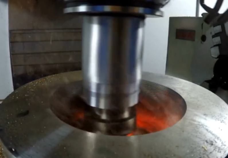
Drilling, Boring, and Hole-Making in Inconel
Hole-making in Inconel is particularly demanding due to chip evacuation and heat accumulation deep in the hole.
Tooling for Drilling Inconel
Options include:
- Solid carbide drills with through-coolant, optimized point geometry, and wear-resistant PVD coatings.
- Carbide-tipped drills for larger diameters in conventional setups.
- High-performance indexable insert drills where machine power and rigidity allow.
Drills should have polished flutes or geometries that facilitate chip evacuation. Through-tool coolant is highly advantageous, especially for deep holes.
Drilling Parameter Ranges
Typical parameter guidelines for carbide drills in Inconel include:
- Cutting speed vc: approximately 10–30 m/min for Inconel 718 and 625.
- Feed per revolution f: in the range of 0.05–0.20 mm/rev depending on drill diameter and tool type.
Peck drilling is often required for deep holes to control chip length and improve evacuation. However, the number of pecks should be minimized to avoid excessive heat cycling on the cutting edges.
Reaming and Boring
Reaming must be done at lower speeds and careful feeds to maintain hole quality without excessive tool wear. Carbide or cermet reamers with through-coolant are preferable. Boring tools should be rigid with minimal overhang and sharp, properly supported edges.
Coolant and Lubrication Strategies
Coolant application significantly affects tool life and surface quality when machining Inconel. Heat management is as important as tool selection and cutting parameters.
Coolant Type and Concentration
Water-soluble cutting fluids with additives for extreme pressure and anti-weld properties are commonly used. Some operations may benefit from oil-based fluids, especially in drilling and tapping, but heat dissipation is generally better with water-based coolants.
Maintaining proper concentration and cleanliness of coolant helps ensure consistent performance and prevents corrosion or residue build-up on tools and workpieces.
Coolant Delivery
High-pressure coolant (e.g., in the range of 50–150 bar, depending on system capability) directed precisely at the cutting zone improves chip breaking and heat removal. For internal operations like deep-hole drilling, through-tool coolant is particularly effective.
Coolant nozzles should be aligned to follow chip flow and to penetrate the cutting zone rather than spraying broadly over the area.
Minimum Quantity Lubrication (MQL)
MQL is less common for Inconel machining due to the high heat load. In some special milling applications with small tools and high cutting speeds, MQL can be used, but careful testing is required.
Workholding, Fixturing, and Machine Requirements
Mechanical stability and accurate positioning are essential for maintaining dimensional tolerances and surface integrity in Inconel machining.
Machine Tool Requirements
Key aspects include:
- High rigidity and robust structure to handle high cutting forces.
- Spindle with sufficient torque at low to medium speeds.
- Accurate servo control and minimal backlash in feed axes.
- Effective coolant delivery system, preferably with high-pressure capability.
Workholding and Fixturing Practices
Workpieces should be clamped securely with minimum possible overhang to reduce vibration. Soft jaws, custom fixtures, and support for thin-walled sections help prevent deformation. When machining thin sections, balanced material removal and careful sequence planning prevent distortion from residual stresses.
Surface Integrity and Metallurgical Considerations
In critical applications, machining must not only achieve geometric accuracy but also preserve the material’s advantageous properties. Surface integrity covers surface roughness, residual stress, microstructural changes, and potential defects.
Surface Roughness Targets
Typical surface roughness requirements for Inconel components vary by application:
- General structural parts: Ra around 1.6–3.2 µm.
- Sealing surfaces, bearing seats, or precision fits: Ra around 0.4–1.6 µm.
Achieving fine surface finish often requires lower feed rates, optimized tool nose radius, and stable cutting conditions with minimal vibration.
Residual Stresses and Work Hardening
Machining can introduce tensile or compressive residual stresses and increase hardness at the surface. Excessive tensile stresses and heavy work hardening can reduce fatigue life and impair performance in high-temperature or cyclic loading environments.
To control these effects:
- Maintain sharp tools and adequate edge support.
- Avoid heavy rubbing and repeated passes over the same surface with low depth of cut.
- Control heat input through correct speeds and coolant application.
Avoiding Surface Damage and Microcracks
Surface defects such as microcracks, laps, tears, and smeared material are unacceptable in critical components. They can be minimized by:
- Choosing tool geometries that avoid aggressive ploughing.
- Refraining from excessive feed marks due to high feed at finishing stages.
- Maintaining consistent cutting conditions without sudden load changes.
Dimensional Accuracy and Tolerances
Nickel-based superalloys like Inconel can exhibit spring-back and thermal expansion effects during machining, influencing dimensional accuracy.
Managing Deflection and Spring-Back
Tool and workpiece deflection can cause undersize or oversize conditions if not considered. Strategies include:
- Minimizing tool overhang and using robust toolholders.
- Adjusting cutting parameters to reduce radial and axial forces.
- Using support features such as tailstocks or steady rests in turning for long parts.
Spring-back of material after cutting means that finishing passes may need to be planned with slightly different allowances compared to steels.
Compensation for Thermal Effects
Heat generated during machining causes thermal expansion of both tool and workpiece. It may be necessary to:
- Allow for part cooling before final measurement and finishing operations.
- Use coolant effectively to stabilize temperature.
- Apply machine tool compensation functions where available.
Burr Control, Deburring, and Edge Quality
Burr formation in Inconel is a common issue at edges, intersections, and hole exits. Burrs may affect assembly, fatigue life, and fluid flow in components.
Burr Reduction at Source
Several approaches help reduce burr formation:
- Optimized cutting direction to keep the burr on a non-critical side of the feature.
- Correct feed, speed, and tool geometry to ensure clean shearing rather than tearing.
- High-quality, sharp tools with appropriate edge preparation.
Deburring Methods
When burrs cannot be completely eliminated, suitable deburring methods include:
- Manual deburring with carbides or abrasive tools for small batches.
- Mechanical brushing with appropriate brush materials and parameters.
- Abrasive flow or vibratory finishing for complex internal passages (depending on tolerances and part configuration).
Process Planning and Machining Strategies for Inconel
Effective Inconel machining is supported by structured process planning that accounts for machine capability, tooling, and target performance.
Roughing, Semi-Finishing, and Finishing Sequence
A multi-stage strategy is often used:
- Roughing: Remove bulk material with robust tools and moderate cutting speeds, prioritizing consistent chip formation and minimal work hardening.
- Semi-finishing: Bring part close to final size, refine surfaces, and prepare uniform allowances for finishing.
- Finishing: Achieve final dimensions and surface quality using stable conditions and carefully selected tools and parameters.
Intermediate stress relief heat treatments may be scheduled for heavily loaded or complex parts, depending on design requirements and residual stress considerations.
Toolpath Selection and CAM Considerations
Toolpaths should preserve constant cutter engagement and avoid abrupt changes in direction or depth of cut. For milling, trochoidal and high-efficiency toolpaths can reduce temperature and increase tool life by limiting radial engagement and maintaining constant chip load.
Inspection, Quality Control, and Documentation
Components made of Inconel are often used in critical systems; therefore, rigorous quality control is necessary.
Dimensional Inspection
Coordinate measuring machines (CMMs), precision gauges, and in-process probing are used to verify dimensions. Inspection should consider that parts must reach thermal equilibrium with the metrology environment, especially after intensive machining.
Surface and Structural Evaluation
Surface roughness can be measured with contact or optical profilometers. For applications where surface integrity is critical, additional examinations may be required:
- Non-destructive testing (NDT), such as dye penetrant or eddy current inspection, to detect surface-breaking discontinuities.
- Metallographic analysis, including microhardness profiles or microstructure evaluation of sample coupons, where specified by standards or customer requirements.
Traceability and Process Documentation
Documenting tool batches, cutting parameters, machine setups, and inspection results allows traceability and facilitates troubleshooting or process refinement in future production runs.
Common Issues and Practical Considerations in Inconel Machining
Certain recurrent technical issues appear frequently in workshops machining Inconel. Recognizing and addressing them helps stabilize production.
Tool Life Variability
Tool life can vary significantly due to small changes in setup or material condition. Factors to control include:
- Consistency of material hardness and heat treatment.
- Uniform cutting fluid concentration and delivery pressure.
- Toolholder clamping force and runout.
Chip Evacuation Problems
Poor chip control can lead to chip nesting around tools or components, re-cutting of chips, and surface damage. Adjusting feed, depth of cut, chipbreaker design, and coolant direction is often necessary to achieve reliable chip evacuation.
Dimensional Drift Over Long Runs
Progressive tool wear and thermal effects can cause dimensions to drift over long production runs. Implementing in-process measurements, tool life monitoring, and planned offset adjustments reduces scrap and rework.
Safety Considerations in Inconel Machining
Machining Inconel generates fine chips and dust, particularly in high-speed operations. Appropriate safety measures include:
- Machine enclosures to contain chips and coolant.
- Proper guarding and interlocks on CNC equipment.
- Coolant management to prevent mist inhalation and skin irritation.
- Personal protective equipment (PPE) such as safety glasses, gloves, and protective clothing.
FAQ
Why is Inconel difficult to machine?
Inconel is difficult to machine because it work-hardens quickly, retains heat, and has high tensile strength, which accelerates tool wear and increases cutting resistance.
Is CNC suitable for Inconel Machining?
Yes, CNC machining is ideal because it provides precision, repeatability, and the ability to maintain consistent cutting parameters.
What grades of Inconel are commonly machined?
Inconel 625, 718, and 600 are among the most commonly machined grades due to their industrial demand.
What coolant is best for Inconel Machining?
High-pressure, water-soluble coolants or oil-based cutting fluids are commonly used to dissipate heat effectively.
How does Inconel Machining affect production cost?
Production costs are typically higher because of slower machining speeds, expensive tooling, and increased machine time.
