
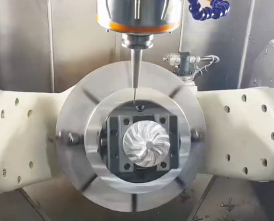
CNC prototyping is one of the most widely used methods for producing precise, functional prototypes from metal and plastic. Understanding how its cost is formed helps engineers, buyers, and product managers make informed design and sourcing decisions and avoid unexpected overruns.
How CNC Prototyping Pricing Is Usually Structured
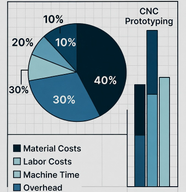
CNC machining service providers commonly build quotations from several cost blocks rather than a single “per part” number. Knowing these components clarifies why two similar-looking quotes can differ significantly.
- Machine and labor time
- Material and stock preparation
- Setup and programming
- Tooling and consumables
- Quality control and documentation
- Secondary operations and finishing
Most shops calculate an internal hourly rate for each machine type (3‑axis mill, 5‑axis mill, turning center, mill‑turn, etc.) that includes depreciation, maintenance, operator labor, and overhead. This rate is multiplied by the estimated machining and setup time, and then material and other items are added.
Material Selection and Its Impact on CNC Prototype Cost
Material choice affects both raw material expense and the machining effort required. Two parts with identical geometry but different materials can have noticeably different prices.
Material Category and Typical Cost Behavior
Basic rules that often apply:
- Common aluminum alloys usually offer low material and machining cost for prototypes.
- Carbon steels are generally economical but may require more cutting effort than aluminum.
- Stainless steels and high‑temperature alloys increase tool wear and cycle time.
- Engineering plastics often machine quickly but may need specialized fixturing to avoid deformation.
| Material Type | Raw Material Cost (Relative) | Machinability | Impact on Tool Wear | Common Prototype Use |
|---|---|---|---|---|
| Aluminum 6061 / 6082 | Low | Very good | Low | General mechanical parts, housings |
| Aluminum 7075 | Medium | Good | Medium | High strength components, aerospace parts |
| Mild Steel (e.g., 1018) | Low | Good | Medium | Shafts, brackets, structural parts |
| Tool Steel (e.g., D2, H13) | Medium to high | Moderate to difficult | High | Molds, wear‑resistant parts |
| Stainless Steel 304 / 316 | Medium to high | Moderate | High | Corrosion‑resistant assemblies, medical components |
| Titanium Alloys (e.g., Ti‑6Al‑4V) | High | Difficult | Very high | Aerospace, implants, high strength/weight ratio parts |
| Brass | Medium | Very good | Low | Fittings, decorative, electrical parts |
| Engineering Plastics (e.g., POM, PEEK, PC) | Low to high (depends on grade) | Good to moderate | Low | Functional prototypes, insulators, medical devices |
Stock Size, Waste, and Procurement
Material cost is not only the weight of the finished part. It includes:
- Standard stock size availability (round bar, plate, block)
- Required oversize for clamping and machining allowance
- Minimum order quantities from suppliers
- Lead time and urgency premiums
A prototype that fits into a standard round bar often costs less than a similar part that requires an oversize plate or custom block, simply because stock utilization and purchasing are more efficient.
Part Geometry and Complexity as Cost Drivers
Geometry determines whether a part can be produced on a simple 3‑axis machine or needs 4‑axis, 5‑axis, or mill‑turn, and how many setups are required. Complexity directly affects cycle time, setup time, programming effort, and required machine type.
Key Geometric Factors
Elements that tend to increase CNC prototyping cost include:
- Deep cavities with high depth‑to‑tool‑diameter ratios
- Thin walls and ribs that are prone to vibration or deflection
- Small internal radii requiring micro tools and low feed rates
- Freeform surfaces requiring multi‑axis simultaneous machining
- Features on multiple faces that require several setups or 5‑axis access
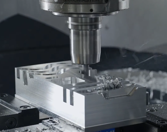
As a rule of thumb, parts that are prismatic and accessible from one or two directions are more economical than parts requiring complex orientation and tool paths.
Feature Density and Machining Time
Every added pocket, hole, thread, or slot contributes to machining time. For example:
If a 3‑axis aluminum part requires 25 minutes of roughing and 15 minutes of finishing, adding numerous precision holes, countersinks, and chamfers can easily add another 10–20 minutes, multiplied by the shop’s hourly rate. On multi‑part prototype orders, this impact accumulates.
Tolerances, GD&T, and Their Pricing Effect
Tolerances define how closely the manufactured part must match the nominal dimensions. Tighter tolerances require slower machining parameters, specific process planning, and more detailed inspection.
Typical Tolerance Ranges
Common tolerance situations in CNC prototypes:
General tolerances: ±0.1 mm (±0.004 in) are easily achievable on most CNC machines without special measures for many materials.
Moderately tight tolerances: around ±0.02–0.05 mm (±0.0008–0.002 in) often require more careful tool selection, stable fixturing, and optimized cutting conditions.
High precision tolerances: in the range of ±0.005–0.01 mm (±0.0002–0.0004 in) may need finishing passes with lower feed, possibly grinding or honing after CNC machining, stable temperature control, and extended inspection processes.
GD&T Callouts and Functional Surfaces
Geometric dimensioning and tolerancing (GD&T) requirements such as flatness, perpendicularity, position, circularity, or runout can significantly influence cost, especially when they apply to large surfaces or multiple features simultaneously.
Cost is mainly affected when:
- Multiple datum references must be controlled in a single setup
- Form tolerances require fine finishing passes and stable clamping
- Positional tolerances on hole patterns require precision drilling/reaming and comprehensive inspection
For CNC prototyping, limiting tight tolerances only to critical functional features reduces cost while keeping the prototype technically valid.
Surface Finish and Post‑Processing Costs
Surface finish requirements influence toolpath strategy, cutting conditions, and additional treatments. A basic machined surface is often the least expensive, while decorative or protective finishes add operations.
| Finish Type | Description | Typical Roughness (Ra) | Added Process Steps | Relative Cost Impact |
|---|---|---|---|---|
| As‑machined | Tool marks visible, no extra finishing | ~1.6–3.2 μm | None beyond machining | Very low |
| Bead blasting | Uniform matte surface | ~3.2–6.3 μm | Masking (if needed), blasting | Low to medium |
| Anodizing (Type II) | Decorative and corrosion‑resistant for aluminum | Depends on base preparation | Chemical treatment, coloring, sealing | Medium |
| Hard anodizing (Type III) | Hard wear‑resistant coating | Depends on process | Thick layer, tighter control | Medium to high |
| Powder coating | Thick decorative and protective coating | Surface texture varies | Pre‑treatment, coating, curing | Medium |
| Polishing | Improved gloss or transparency | Sub‑micron possible | Manual or semi‑automatic polishing steps | High (especially for complex shapes) |
| Plating (e.g., nickel, chrome) | Corrosion resistance, appearance | Depends on substrate and process | Surface activation, plating, sometimes polishing | Medium to high |
Base Finish from the CNC Machine
The base finish is mainly determined by:
- Tool type and geometry
- Spindle speed and feed per tooth
- Step‑over and step‑down strategy on planar and 3D surfaces
- Machine tool condition (spindle runout, rigidity)
Where the drawing allows a broader roughness range, machining time and cost can be lower, because heavier cuts and larger step‑overs are acceptable.
Quantity, Batch Size, and Economies of Scale
CNC prototyping is often associated with small quantities, but even within low volumes, batch size has a significant impact on the unit price.
Setup and Programming Distribution
Setup and programming represent largely fixed costs for a given part geometry. They may include:
- CAM programming and toolpath verification
- Machine setup (tool loading, probing, offset setting)
- First‑article trial and adjustment
If a part requires 3 hours of combined programming and setup, producing 1 piece versus 20 pieces dramatically changes the per‑unit allocation of those hours. For that reason, quotes for 1, 5, 10, and 50 pieces can show decreasing unit costs even when machining time per piece remains almost identical.
Practical Planning Consideration
When possible, grouping prototype needs into slightly larger batches can reduce cost per part. However, for early design verification, ordering a very small batch may still be more economical overall than overproducing parts that later become obsolete after design iteration.
Setup, Programming, and Fixturing Effort
Setup and fixturing complexity influences both cost and lead time. Some prototypes are easily clamped using standard vises or chucks, while others need custom fixture design and manufacturing.
Programming Complexity
CAM programming effort increases with:
- Number of operations and tool changes
- Multi‑axis strategies for freeform surfaces
- Critical collision avoidance on 5‑axis machines
- Requirement for optimized tool paths to achieve demanding tolerances or surface finishes
For simple prismatic parts, programming can be relatively quick. For complex 3D surfaces, sculpted components, or parts needing simultaneous 5‑axis machining, programming may take several hours, and this time must be paid for even if only a few pieces are produced.
Fixturing and Workholding
Workholding decisions affect repeatability and handling time between operations. Considerations for fixturing include:
- Part stiffness and clamping force limits
- Required access to multiple faces in a single setup
- Datums and reference surfaces according to the drawing
- Use of soft jaws, vacuum fixtures, or dedicated plates
Custom fixtures add design and machining effort but may be justified for prototypes that are expected to evolve into low‑volume production, where the fixture can then be reused.
Machine Type and Axis Count Influence on Cost
The choice of machine tool directly influences both hourly rate and available capability. More sophisticated machines cost more to own and operate but can reduce setups and improve overall accuracy for complex parts.
Typical Machine Categories
Common machine types used in CNC prototyping include:
- 3‑axis vertical machining centers
- 4‑axis mills with rotary tables or trunnions
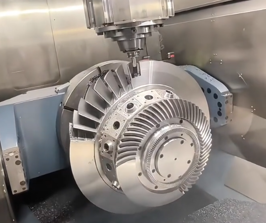
- 5‑axis simultaneous machining centers
- CNC lathes (2‑axis turning)
- Mill‑turn centers with live tooling and Y‑axis
3‑axis machines are economical for flat and prismatic parts. 5‑axis machines are chosen for parts with features on multiple faces or complex 3D geometry. Although the hourly rate of a 5‑axis machine generally exceeds that of a 3‑axis machine, the reduction in setups and greater flexibility often justify its use for certain prototypes.
Inspection, Quality Control, and Documentation
Quality control is not only a technical requirement but also a cost element. CNC prototypes may require different levels of inspection, from simple dimensional verification with calipers to complete reports based on CMM measurements.
Inspection Scope
Inspection cost is influenced by:
- Number of dimensions and features to check
- Measurement methods (hand tools, gauges, CMM, optical devices)
- Sampling plan (100% inspection vs. partial sampling)
- Formal documentation (FAI reports, material certificates, traceability)
A prototype project that includes full first‑article inspection, with traceable records of key characteristics, naturally costs more than one where only basic checks are required. When specifying inspection requirements, aligning them with the prototype’s actual use and risk level avoids unnecessary cost.
Secondary Operations and Assembly
Many CNC prototypes require operations beyond basic milling or turning, which contribute additional cost and scheduling steps.
Common Secondary Operations
Frequently requested operations include:
- Thread rolling or thread forming (for specific fasteners and materials)
- Heat treatment for steels (hardening, tempering, stress relieving)
- Welding or brazing of multiple CNC‑machined components
- Press‑fit or bonded assembly of inserts, bushings, or bearings
- Laser marking, engraving, or part identification
Each additional step introduces handling time and often requires external processes (for example, outsourced heat treatment or surface treatment), which can lead to added logistics cost. For early prototypes, simplifying assembly or reducing the number of post‑machining operations can lead to a more economical overall solution.
Project Management, Lead Time, and Urgency
Lead time requirements strongly influence CNC prototyping cost. Shorter deadlines often require overtime, priority scheduling, or parallel machine use, all of which increase cost.
Standard vs. Expedited Delivery
Standard lead times allow the shop to sequence jobs optimally and share machines among multiple customers. Expedited projects must be prioritized, sometimes interrupting current jobs and using additional resources to achieve the requested delivery date. This is typically reflected in higher quotation values for the same part when requested on a rush basis.
Design and Cost Optimization Considerations
Many cost‑related factors can be influenced at the design stage. Design for manufacturability principles allow engineers to maintain functionality while reducing machining complexity and processing time.
Typical Cost‑Relevant Design Decisions
Some examples of decisions that influence prototype cost include:
- Using hole sizes and threads that match standard tools and taps
- Relaxing non‑critical tolerances to general machining ranges
- Simplifying undercuts and internal features that require special tooling
- Keeping wall thicknesses and ribs within ranges that can be machined without excessive deflection
- Consolidating features to reduce the number of setups or required machine orientations
When cost is a major concern, exchanging 3D models and drawings with the machining supplier and discussing alternative solutions often results in a more efficient design while still meeting functional requirements.
Common Cost‑Related Issues in CNC Prototyping
Certain recurring issues frequently lead to higher‑than‑expected CNC prototyping costs. Recognizing them early helps avoid budget problems.
Ambiguous Drawings and Incomplete Specifications
Drawings with unclear dimensions, missing tolerances, or incomplete material and finish specifications require additional clarification. Time spent resolving these points is part of the project cost and may delay the quotation process.
Mixing Prototype and Production Requirements
Sometimes prototypes are specified with the same documentation and traceability level as full production parts, including extensive inspection plans and certifications. Unless essential for the objective of the prototype, these requirements can significantly increase cost without adding corresponding value at the prototype stage.
