
Custom flange machining is the process of manufacturing non‑standard or special flanges by removing material from metal stock to achieve specified dimensions, faces, bores, bolt patterns, and sealing features. It is widely used in piping, pressure vessels, pumps, compressors, valves, and rotating equipment where standard catalog flanges cannot meet specific design, space, or performance requirements.
Scope and Application of Custom Flange Machining
Custom machined flanges are applied when standard ASME, EN, or other catalog flanges cannot satisfy particular needs related to pressure rating, geometry, material, or integration with existing equipment. Typical applications include:
- Adapting legacy or proprietary connections in brownfield facilities
- Integrating pumps, compressors, or heat exchangers from different standards
- Accommodating special gaskets, sealing faces, or instrument ports
- Handling high‑temperature, corrosive, or abrasive media
Custom flanges may be produced in single pieces, small batches, or medium series, with machining strategies and cost structures adjusted to suit each volume range.
Types of Custom Flanges and Key Features
While terminology varies by region and standard, most custom flanges are derived from well‑known categories, modified in dimensions, drilling, or materials. Common flange configurations include:
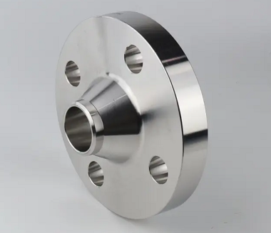
Weld Neck and Long Weld Neck Flanges
Weld neck flanges feature a tapered hub that is butt‑welded to the pipe, providing smooth stress distribution in high‑pressure and high‑temperature service. Customization often relates to:
- Non‑standard neck length or taper for stress or space requirements
- Special bore to match custom pipe schedules or heavy‑wall components
- Modified hub OD to clear adjacent structures or insulation
Long weld neck flanges extend the hub length, often used for vessel nozzles, with precise machining of bore, face, and transition radius to ensure proper flow and weld quality.
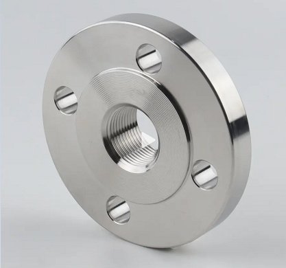
Slip‑On, Socket Weld, and Threaded Flanges
These flanges are used primarily for small‑bore piping, moderate pressures, and compact arrangements. Custom machining commonly focuses on:
Slip‑on flanges – Modified thickness, raised face or flat face, non‑standard bolt circle diameters, or combination bolt patterns to link different standards.
Socket weld flanges – Precisely machined socket depth, shoulder radius, and bore to control weld penetration and alignment with small‑diameter pipes.
Threaded flanges – Customized thread type (NPT, BSP, special taper), thread tolerances, and thread relief to match existing threaded connections or special equipment.
Blind, Orifice, and Spectacle Flanges
Blind flanges close the end of a line or vessel opening. Custom versions may integrate instrument ports, inspection openings, or reinforcement features. Orifice flanges incorporate machined recesses, taps, and alignment features for flow measurement plates. Spectacle and spacer flanges are manufactured by profile cutting and finish machining for quick changeover between blind and open configurations.
Special Geometry and OEM Flanges
In many cases, flanges must match the interface geometry of OEM equipment such as pumps, turbines, or valves. These flanges often require:
Non‑circular outlines, asymmetric bolt patterns, precision alignment dowels, and machined pockets or grooves for O‑rings and profile gaskets. Flange machining in these cases depends heavily on accurate CAD data and robust fixturing to reproduce complex shapes consistently.
Technical Requirements and Dimensional Parameters
Custom flanges must satisfy a combination of design, functional, and manufacturing requirements. Careful definition of key parameters reduces rework and cost. Typical dimensional and technical parameters include:
Dimensional Standards and Interfaces
Even when dimensions are custom, they are usually referenced to existing standards for compatibility. Common standards include ASME B16.5, ASME B16.47, EN 1092‑1, and various JIS, GOST, or manufacturer‑specific norms. Important dimensional aspects:
Nominal pipe size (NPS or DN) – Governs bore and exterior dimensions where standard pipes are connected. Pressure class – Determines minimum flange thickness, bolt size, and gasket contact area. Bolt circle diameter, number of holes, and bolt hole size – Critical for interchangeability and load distribution. Raised face height, ring‑joint groove dimensions, and tongue‑and‑groove geometry – Define gasket seating and sealing performance.
Tolerances and Fits
Dimensional tolerances in flange machining ensure proper assembly, sealing, and mechanical integrity. Typical tolerance considerations include:
Overall dimensions – Outside diameter, thickness, and hub length generally held to ISO or ASME tolerances based on size and function. Bore tolerances – Dictate the fit between flange and mating pipe or nozzle; common fits range from close sliding to interference, depending on welding and alignment requirements. Bolt hole tolerances – Typically set to allow bolt insertion without excessive clearance; position tolerances are essential to prevent assembly misalignment. Concentricity and runout – Concentricity between bore and bolt circle and face runout must be controlled to prevent gasket over‑compression, leakage, or misalignment in rotating equipment interfaces.
Surface Finish and Sealing Faces
Surface finish on the sealing face has a direct impact on gasket performance and sealing reliability. Standard requirements often specify the Ra (arithmetic average roughness) and the tool lay pattern. Typical practices:
Raised face for soft gaskets – Common surface roughness in the range of 3.2–6.3 μm Ra, with a continuous spiral serration to create micro‑channels that enhance gasket seating. Ring‑type joint (RTJ) grooves – Precision machined grooves with tighter tolerances and smoother surfaces to suit metallic ring gaskets; groove dimensions are controlled to ensure correct gasket compression. Flat face for brittle or full‑face gaskets – Usually finer surface finish to distribute load uniformly, especially for cast iron or glass‑lined equipment. Tongue‑and‑groove or male‑female faces – Require consistent width, depth, and alignment to ensure positive gasket confinement and prevent extrusion.
Materials for Custom Flange Machining
Material selection for custom flanges considers pressure, temperature, medium composition, corrosion allowance, weldability, and mechanical properties. Machinability and availability also influence cost and delivery time.
| Material Category | Common Grades | Key Properties | Machinability | Typical Use Cases |
|---|---|---|---|---|
| Carbon & Low Alloy Steel | A105, A350 LF2, A694 F52–F65 | Good strength, economical, suitable for moderate to high pressure, wide temp ranges | Generally good; low alloy may require optimized tooling | General process piping, oil & gas, power, structural nozzles |
| Stainless Steel | A182 F304/L, F316/L, F321, F347 | Corrosion resistance, good cryogenic performance, non‑rusting surfaces | Moderate; work hardening requires controlled cutting conditions | Chemical, food, pharma, water treatment, clean services |
| Duplex & Super Duplex | F51 (2205), F53, F55 | High strength, excellent chloride stress corrosion resistance | More difficult; demands rigid setups, lower cutting speeds | Offshore, seawater systems, aggressive chloride environments |
| Nickel & High‑Nickel Alloys | Alloy 625, 825, C‑276 | Outstanding corrosion resistance, high temp strength | Challenging; tool wear and heat must be managed carefully | Acid handling, high‑temperature, severe corrosion services |
| Aluminum & Non‑Ferrous Alloys | 6082, 6061, bronze, brass | Lightweight, good conductivity, specific corrosion profiles | Generally easy; risk of built‑up edge in some alloys | Low‑pressure systems, instrumentation, lightweight structures |
| Specialty Materials | Titanium, zirconium | High strength‑to‑weight, excellent corrosion resistance in specific media | Demand careful control of heat and cutting parameters | Aerospace, high‑end chemical, nuclear service |
Pre‑Machining Preparation and Stock Production
Before precision machining, flange blanks must be produced in forms that balance material utilization with machining time. Common blank production methods include forging, plate cutting, and bar/round stock preparation.
Forged Flange Blanks
Forged blanks are widely used for pressure‑bearing flanges and critical services. The forging process refines the grain structure, improving mechanical properties and reliability. Typical steps:
Heating billets or ingots to forging temperature, open‑die or closed‑die forming to approximate flange shape, trimming excess material, controlled cooling, and subsequent heat treatment. Machining allowances are included on OD, thickness, and faces to allow full cleanup and accurate dimensions.
Plate‑Cut and Burned Blanks
For larger diameter or low‑pressure flanges, blanks can be cut from plate using oxy‑fuel, plasma, or waterjet processes. After cutting, thermal distortions are mitigated by controlled cooling or stress‑relief heat treatment. Machining then removes the heat‑affected zone and establishes precise dimensions, faces, and bores.
Round Bar and Hollow Bar
Small‑diameter or ring‑type flanges may be machined from solid bar or hollow bar. This approach reduces forging tooling costs and is well suited to low‑volume custom work. Material removal is higher, but stock availability and flexible geometry often offset the extra machining time.
Core Machining Methods for Custom Flanges
Custom flange machining combines several processes to achieve the required geometry and finish. The choice of machine tools and methods depends on size, complexity, material, and batch size.
Turning Operations
Turning is the primary operation for circular flanges. CNC lathes or vertical turning lathes are used to machine:
Outside and inside diameters – Rough and finish turning to size, with allowances for subsequent finishing if needed. Flange faces – Machined flat, raised, or profiled sealing surfaces with controlled surface roughness and tool lay. Hubs and necks – Tapered or stepped profiles, accurate lengths, and blending radii to match design and stress requirements. Ring‑joint grooves and gasket recesses – Precision turned and grooved with appropriate form tools to conform to RTJ, O‑ring, or custom gasket specifications.
Drilling and Tapping
Drilling forms bolt holes, instrument ports, and threaded connections. Key aspects:
Bolt circle drilling – Coordinated on CNC machining centers or drilling jigs to maintain accurate pitch circle diameter, hole spacing, and orientation. Counterboring – Used for socket head cap screws or bolt head recesses where clearance is limited. Threaded holes – Machined using tapping or thread milling, with careful control of alignment and depth for blind holes.
Milling and Profiling
Milling operations are employed when flanges require non‑round profiles, flats, keyways, alignment features, or specific mounting geometries. Typical milling tasks:
Machining of non‑circular outer shapes to match OEM equipment or structural limitations. Slotting and keyway creation for shaft connections or anti‑rotation features. Machining of alignment pads, ribs, or mounting feet as part of complex adapter flanges. Milling of grooves and pockets where turning is not feasible due to geometry.
Boring, Facing, and Counterboring
Internal bores and critical faces often require boring operations on horizontal or vertical machines for accuracy and surface finish. Applications include:
Accurate bore sizing for tight fits with pipes or vessel nozzles. Counterbores at gasket faces to accommodate special seal carriers or step gaskets. Precision facing of multiple surfaces in one setup to control parallelism and squareness, especially important for multi‑flange assemblies or stacked components.
CNC vs. Manual Machining
CNC equipment enhances repeatability, speed, and complex path control, especially for multi‑operation flanges and medium series production. Manual lathes and mills remain viable for single‑piece or very low volume work, particularly for simple geometries or repair flanges. Selection is influenced by flange size, tolerances, geometry complexity, and lead time requirements.
Heat Treatment, Stress Relief, and Hardness Control
Heat treatment is frequently integrated with flange machining to achieve required mechanical properties and dimensional stability. Common practices:
Normalizing and quenching/tempering for carbon and low‑alloy steels to achieve specified strength and toughness. Solution annealing for stainless steels to restore corrosion resistance and relieve work hardening. Stress relief after heavy machining or thermal cutting to reduce residual stresses and minimize distortion during final machining and service. Hardness control to meet code and customer requirements, monitored by hardness testing at specified locations on the flange.
Surface Treatments and Corrosion Protection
After machining, flanges may receive additional treatments to enhance corrosion resistance, cleanliness, or appearance. Typical options include:
Shot blasting or sandblasting – Removes scale and machining residues, providing a uniform surface for coating or painting. Painting systems – Epoxy, polyurethane, zinc‑rich primers, or other coating systems according to environmental exposure and client specifications. Electroplating or galvanizing – Zinc plating or hot‑dip galvanizing for carbon steel flanges in atmospheric or buried service. Passivation – Chemical treatment of stainless steels to enrich the chromium oxide layer and remove free iron from machining processes. Phosphate or other conversion coatings – Provide temporary corrosion protection during storage and transport.
Inspection, Testing, and Quality Control
Systematic inspection and testing ensure that custom flanges conform to drawing specifications, standards, and service requirements. Quality control spans from incoming raw material to final inspection.
Dimensional and Visual Inspection
Dimensional checks use calipers, micrometers, height gauges, bore gauges, and coordinate measuring machines. Critical dimensions such as OD, thickness, bore, bolt circle, bolt hole diameter, and face flatness are verified. Visual inspection identifies surface defects, machining marks, burrs, sharp edges, and coating quality, with specific acceptance criteria for sealing areas.
Nondestructive Examination (NDE)
Depending on service criticality and specifications, nondestructive testing methods may include:
Ultrasonic testing – Evaluates internal soundness of forged or plate‑cut blanks. Magnetic particle testing – Detects surface and near‑surface cracks in ferromagnetic materials, especially in weld‑repaired areas. Dye penetrant testing – Used on non‑magnetic materials, such as stainless steels, to find surface‑breaking discontinuities. Radiographic testing – Applied when there are weldments in the flange or flange‑to‑pipe assemblies.
Pressure, Leak, and Functional Testing
Where required, flanges integrated into assemblies may undergo hydrostatic or pneumatic testing to a specified pressure. Leak testing of sealing faces and gasket interfaces can also be performed using helium, air, or other media according to sensitivity requirements. Functional tests may include assembly trials with mating components to verify fit and alignment.
Cost Structure in Custom Flange Machining
The cost of custom flange machining results from multiple interacting factors. Understanding these elements helps optimize designs for manufacturability and budget adherence.
| Cost Component | Description | Factors Affecting Magnitude |
|---|---|---|
| Material Cost | Base metal required for flange blanks and machining allowances | Material grade, size and thickness, stock form (forging, plate, bar), market price |
| Machining Time | Actual cutting hours on lathes, mills, drills, and boring machines | Flange size and complexity, tolerances, surface finish, tool paths, machine type |
| Setup and Programming | Preparing fixtures, programming CNC, and first‑article run | Batch size, part complexity, need for special jigs, frequency of design changes |
| Tooling and Consumables | Cutting tools, inserts, drill bits, coolants, gauging tips | Material machinability, cutting parameters, required tolerances and finishes |
| Heat Treatment & NDE | Thermal processing, stress relief, and nondestructive testing | Material grade, service class, code requirements (e.g., pressure vessel, offshore) |
| Coating and Finishing | Surface preparation, painting, plating, passivation | Environmental exposure, customer specifications, coating system complexity |
| Quality Documentation | Certificates, inspection reports, traceability records | Industry standards, project requirements, client audit level |
| Overhead and Logistics | Administrative, handling, packaging, and transport costs | Order size, destination, protective packaging, export requirements |
Typical Cost Considerations and Optimization
Project planners and engineers can influence flange machining costs by refining specifications and coordinating early with manufacturers. Key considerations include:
Material selection – Choosing a grade with adequate, but not excessive, corrosion and mechanical performance reduces material and machining costs. Standardization of features – Aligning face types, bolt patterns, and thicknesses across a project reduces setup variety and simplifies tooling. Tolerance rationalization – Specifying tolerances and surface finishes only as tight as functionally necessary reduces machining time and inspection costs. Batch consolidation – Grouping similar flanges in one order improves machine utilization and lowers setup time per piece. Design for manufacturability – Avoiding unnecessary complex contours or transitions that do not contribute to performance limits machining steps.
Common Issues in Custom Flange Machining and Practical Considerations
In practice, several recurring issues appear when specifying and producing custom flanges. Addressing them in the design and sourcing stages improves reliability and lead times.
Dimensional Misalignment and Assembly Fit
Misalignment in bolt circles, bores, or faces can prevent flanges from assembling properly or cause gasket seating problems. To minimize this risk, consistent coordinate systems, accurate drawings, and clear reference dimensions are essential. When matching existing equipment, precise measurement of the mating flange using calibrated tools or 3D scanning is recommended.
Material Availability and Lead Time
Some special alloys or large‑size forgings have long procurement lead times. Early confirmation of material availability and potential substitution options helps avoid schedule delays. For small quantities, using plate or bar stock may provide faster delivery than custom forgings, with the trade‑off of additional machining.
Surface Finish and Gasket Compatibility
Inappropriate surface finish on sealing faces can lead to leakage, excessive gasket compression, or premature gasket failure. Matching the specified Ra and lay pattern to the gasket type and pressure class ensures reliable sealing. It is important to specify any special requirements for metallic, spiral wound, or profile gaskets clearly on the drawing.
Documentation and Traceability
Industrial and regulated applications often require full documentation of material origins, heat treatment records, inspection results, and NDE reports. Establishing documentation requirements at the quotation stage ensures that all records are captured and certified during production rather than reconstructed later.
Best Practices for Specifying Custom Machined Flanges
Effective communication between engineering, procurement, and machining suppliers reduces iterations and unforeseen costs. Useful practices include:
Providing complete drawings with all necessary views, dimensions, tolerances, and surface finish symbols. Referencing applicable standards for dimensional, material, and testing requirements. Defining sealing face types, gasket types, and target roughness values. Specifying inspection and testing requirements, including NDE methods and acceptance criteria. Clarifying any special packaging, labeling, or preservation needs for shipping and storage. When possible, sharing 3D models in neutral formats to assist CNC programming and collision checking.
