
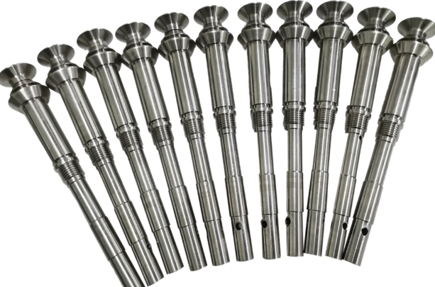
A shaft is a rotating machine element used to transmit power and motion from one component to another. Shafts support rotating parts such as gears, pulleys, flywheels, couplings, and rotors, and they operate under combined torsional, bending, and sometimes axial loads. This guide explains the definition, functions, engineering classifications, materials, design parameters, surface treatments, and machining processes for shafts in a technically structured way.
Fundamental Definition and Functions of Shafts
A shaft is typically a cylindrical member designed to carry torque and associated loads while rotating about its axis. In power transmission systems, the shaft links the prime mover (electric motor, engine, turbine) to driven machines (pumps, compressors, conveyors, machine tools).
Key functions include:
- Transmitting torque and rotational motion between components
- Supporting rotating elements such as gears, pulleys, sprockets, rotors, and couplings
- Maintaining precise alignment between supported elements and bearings
- Accommodating bending loads from belt tensions, gear forces, and self-weight of components
Engineering design of shafts aims to satisfy strength, stiffness, fatigue life, manufacturability, and assembly requirements, while keeping cost, weight, and envelope dimensions within specified limits.
Engineering Classification of Shafts
Shafts can be classified by function, cross-section, geometry, and manufacturing method. In power transmission and machine design, functional classification is commonly used.
Transmission Shafts
Transmission shafts carry power between power generation and consuming devices over certain distances. They usually operate at moderate to high speeds and must withstand torsional and bending stresses.
Typical examples:
- Countershafts and layshafts in gearboxes
- Line shafts in workshops, mills, or processing lines
- Propeller shafts in vehicles and ships
Transmission shafts often carry pulleys, gears, couplings, and sprockets, and include features such as keyways, splines, and shoulders.
Machine Shafts
Machine shafts form an integral part of a machine and are not simply connecting elements. They often have more complex geometry and interface surfaces.
Examples include:
- Crankshafts in engines and compressors
- Rotor shafts in electric motors and generators
- Camshafts in internal combustion engines
These shafts are often subject to complex cyclic loading and require careful fatigue and dynamic analysis.
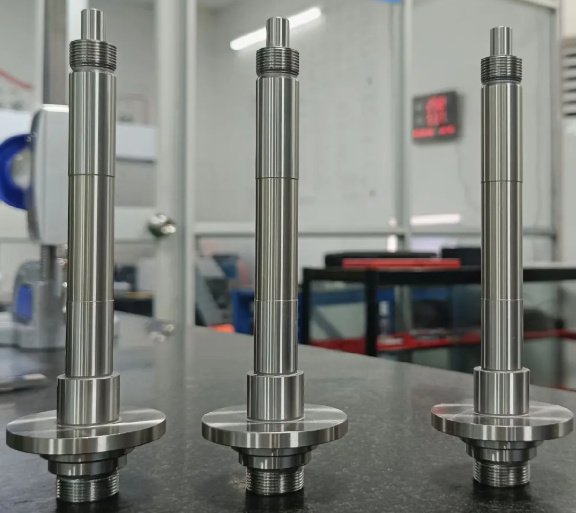
Spindles
Spindles are relatively short shafts that support tools or workpieces, usually in machine tools or precision equipment. They prioritize stiffness, runout control, and high rotational accuracy.
Common spindle applications:
- Lathe spindles for workpiece holding
- Milling and machining center spindles for tool holding
- Grinding spindles for wheel mounting
Axles and Stub Shafts
An axle is a non-rotating or slowly rotating member that supports rotating elements such as wheels. While axles primarily carry bending loads, many design principles overlap with shaft design, especially for combined load conditions.
Stub shafts are short lengths of shaft integral or attached to a larger rotating element, such as the projecting shaft end of a motor or gearbox, used for coupling connection or mounting auxiliary components.
Classification by Cross-Section and Geometry
Shafts are most commonly circular in cross-section, but other shapes are used for specific requirements:
Circular shafts: Solid or hollow, round cross-section, isotropic torsional properties and convenient to manufacture.
Hollow shafts: Reduced weight for the same torque capacity and increased torsional rigidity-to-weight ratio. They are common in automotive drive shafts, aerospace applications, and large rotating equipment.
Non-circular shafts: Square, hexagonal, or splined geometries used when positive torque transmission without keys is required, or when indexing is necessary. These are usually over short lengths.
Key Design Parameters and Mechanical Considerations
Shaft design requires evaluation of mechanical strength, stiffness, fatigue life, dynamic behavior, and compatibility with bearings and mounted components. The following parameters are central to shaft engineering.
Torque Capacity and Torsional Stress
Shafts must safely transmit the maximum torque expected in service, including transient and starting conditions. Torsional shear stress is typically limited by allowable material stress and design safety factors.
For a solid circular shaft subjected to torque T:
τmax = (16T) / (π d³)
where d is the shaft diameter.
For a hollow shaft with outer diameter do and inner diameter di:
τmax = (16T) / [π (do⁴ − di⁴) / do]
Allowable torsional stress is selected based on material yield strength, ultimate strength, and desired safety factor, accounting for stress concentrations from shoulders, keyways, and grooves.
Bending Loads and Combined Stress
Shafts carry bending moments due to weights of gears, pulleys, couplings, and belt tensions, as well as gear mesh reactions. Combined bending and torsion produce equivalent stress, which is commonly evaluated using distortion energy or maximum shear stress theories.
Combined stress analysis considers:
- Bending moment diagrams along the shaft length
- Torsional moment distribution from transmitted power
- Resultant equivalent stresses at critical sections
Shaft Deflection and Stiffness
Excessive shaft deflection can cause misalignment, uneven gear tooth loading, vibration, and premature bearing failure. Stiffness constraints often control shaft diameter more than strength in high-speed and precision applications.
Key stiffness considerations:
- Maximum allowable lateral deflection to meet gear mesh or coupling alignment limits
- Slope at bearing locations and near gears or couplings
- Torsional angle of twist over critical spans
Critical Speed and Dynamic Behavior
Rotating shafts have natural frequencies; if operating speed approaches a natural frequency, resonance and large vibrations may occur. Critical speed analysis ensures that operating speeds are either below the first critical speed or that the shaft system is adequately designed for supercritical operation.
Parameters influencing critical speed:
- Mass distribution and locations of attached components
- Shaft stiffness and support conditions
- Damping within bearings and couplings
Stress Concentration and Fatigue Life
Shafts often fail by fatigue at geometric discontinuities such as shoulders, keyways, retaining ring grooves, and threaded ends. Design must minimize stress concentration factors and select appropriate surface treatment and fillet radii.
Common measures include:
- Generous fillet radii at diameter steps
- Smooth transitions between sections and features
- Use of splines instead of deep keyways for high torque
Standard Shaft Dimensions and Tolerance Considerations
Many shafts follow standardized dimensions and tolerance systems to simplify design and ensure interchangeability with bearings, couplings, and other components.
Standard Diameters
Standard shaft diameters often follow preferred number series (e.g., R10, R20), as well as bearing inner diameter series used in rolling bearings. Typical preferred ranges include small diameters from a few millimeters for precision spindles to several hundred millimeters for heavy-duty industrial shafts.
Fits and Tolerances
Fits between shafts and mating components are selected based on functional requirements such as torque transmission, assembly method, and disassembly frequency.
| Fit Type | Functional Description | Typical Applications |
|---|---|---|
| Clearance fit | Small intentional gap; free or easy sliding assembly | Bearings requiring free rotation on shafts, easily removable couplings, pulleys mounted with set screws |
| Transition fit | Either slight clearance or slight interference | Gears or hubs requiring accurate location but removable with moderate force |
| Interference fit | Intentional overlap; press or shrink fit | Permanent or semi-permanent mounting of gears, rotors, couplings, and bearing inner rings |
Standards such as ISO tolerance systems define shaft designation letters (e.g., h, k, n) and IT grades. Selection considers load, torque, surface finish, thermal conditions, and assembly method (press, shrink, or hydraulic mounting).
Materials for Shafts and Their Properties
Material selection affects strength, fatigue resistance, weight, machinability, corrosion resistance, and cost. Carbon steels are widely used, but alloy steels, stainless steels, aluminum alloys, and other materials are specified for particular environments and performance requirements.
Carbon Steels
Plain carbon steels are commonly used for general-purpose shafts where very high strength or special environmental resistance is not required.
Typical categories:
- Low carbon steels: Good ductility and weldability, moderate strength, used for lightly loaded shafts, line shafts, and general machinery shafts
- Medium carbon steels: Higher strength and hardness after heat treatment, used in automotive and industrial shafts subjected to heavier loads
Alloy Steels
Alloy steels containing elements such as chromium, nickel, molybdenum, or vanadium provide improved strength, hardenability, and fatigue resistance. They are used in highly loaded or safety-critical shafts.
Typical applications:
- Crankshafts and camshafts
- Heavy-duty gear shafts and turbine shafts
- High-speed spindle shafts requiring high fatigue strength
Stainless Steels
Stainless steel shafts are used where corrosion resistance is essential, such as in food processing machinery, marine equipment, chemical processing plants, and pharmaceutical machinery.
Common types:
- Austenitic stainless steels for excellent corrosion resistance and good formability
- Martensitic stainless steels where higher strength and hardness with moderate corrosion resistance are needed
Aluminum and Non-Ferrous Alloys
Aluminum shafting offers reduced weight with moderate strength, useful in aerospace, robotics, and light-duty drive systems. For high-strength requirements with weight minimization, certain high-strength aluminum alloys and other non-ferrous alloys are chosen.
Non-ferrous shaft materials are also used for special properties such as non-sparking behavior, electrical conductivity, or improved corrosion resistance (e.g., copper alloys in certain marine or chemical environments).
Composite Shafts
In specific applications where weight reduction and high stiffness are critical, such as high-speed drive shafts and aerospace components, composite shafts with fiber-reinforced polymer construction are used. They offer high specific stiffness and can be tailored for anisotropic properties.
Heat Treatment and Surface Treatments for Shafts
Heat treatment and surface modification processes improve strength, hardness, wear resistance, and fatigue performance. Selection depends on base material and service conditions.
Common Heat Treatment Processes
Heat treatment processes for shaft steels include:
- Normalizing: Refines grain structure and improves machinability, used for general-purpose shafts
- Quenching and tempering: Increases strength and toughness of medium and alloy steels
- Case hardening: Produces a hard wear-resistant surface with a tough core, typically by carburizing, carbonitriding, or nitriding
Surface Treatments and Coatings
Surface treatments are applied to enhance fatigue strength, corrosion resistance, and wear behavior.
Typical treatments:
- Induction hardening: Local surface hardening of critical regions such as bearing seats and gear mounting surfaces
- Nitriding: Produces a hard, wear-resistant surface layer with minimal distortion
- Hard chrome plating: Improves wear and corrosion resistance and allows dimension correction
- Phosphate or oxide coatings: Provide limited corrosion protection and improved lubricant retention
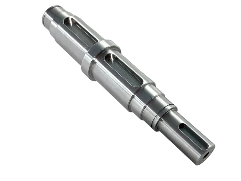
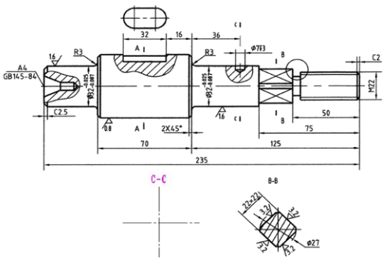
Shaft Features: Shoulders, Keyways, Splines, and Threads
Shafts incorporate various geometric features to accommodate components, transmit torque, and enable assembly. These features introduce stress concentrations, so design must balance functionality with strength.
Shoulders and Steps
Shoulders are diameter transitions that provide axial location for bearings, gears, pulleys, and collars. Proper fillet radii and surface finish at shoulders are important for fatigue strength.
Keyways and Keys
Keyways are longitudinal slots in shafts and hubs that accommodate keys to transmit torque between shaft and mounted components.
Common key types:
- Parallel keys: Rectangular cross-section, widely used for general torque transmission
- Taper keys: Provide tight fit with wedge action, often used where disassembly is infrequent
Keyways reduce shaft strength due to reduced cross-section and increased stress concentration. This effect is considered in design by applying correction factors in stress calculations.
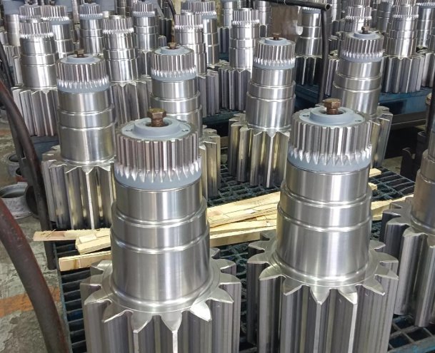
Splines
Splines consist of multiple tooth-like projections on the shaft engaging mating grooves in the hub. They distribute torque over several teeth, improving load capacity and alignment compared with single keys.
Advantages include:
- Higher torque capacity
- Better concentricity and alignment of mounted components
- Capability for axial sliding of hubs in sliding-spline designs
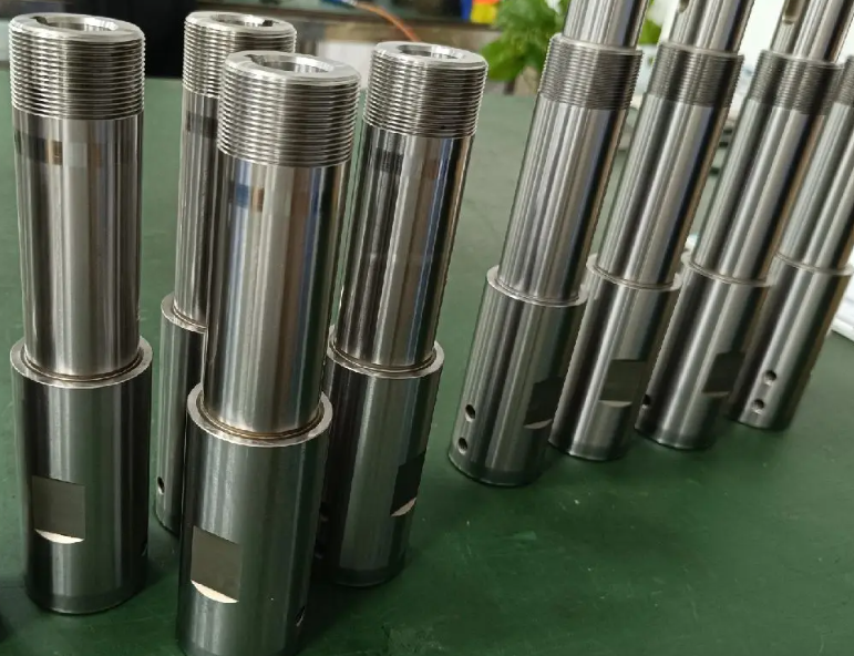
Threads
Threads on shafts are used for nuts, end fasteners, and adjustment mechanisms. Because threads have high stress concentration, heavily loaded shaft regions are usually unthreaded, and threads are positioned in lower-stress areas or are provided with relief grooves and fillets.
Machining Processes for Shafts
Machining converts raw material into finished shafts with specified geometry, tolerances, and surface finish. Process selection depends on required accuracy, production volume, material, and cost constraints.
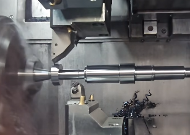
Turning and Centerless Turning
Turning on lathes is the primary method for producing cylindrical shaft surfaces. Operations include rough and finish turning to bring shafts to required diameter and straightness.
Centerless turning or centerless grinding is used for shafts where high concentricity and tight diameter control over long lengths are required. It supports the shaft without centers, reducing deformation and enabling uniform material removal.
Grinding
Grinding is applied to achieve fine surface finish, tight tolerances, and precise cylindricity, particularly on bearing seats, seal surfaces, and critical diameter fits.
Types of grinding used for shafts:
- Cylindrical grinding for external diameters
- Centerless grinding for long, slender shafts
- Internal grinding for bores in hollow shafts or hubs
Keyway and Spline Machining
Keyways are machined using milling, slotting, or broaching. For high-volume production, broaching provides accurate and repeatable profiles.
Splines are produced by:
- Hobbing or shaping for external splines
- Broaching or shaping for internal splines
Drilling, Boring, and Threading
Drilling and boring operations create axial holes for lubrication passages, weight reduction, or for forming hollow shafts. Threading is performed by turning, rolling, or tapping, depending on thread size, accuracy, and production volume.
Finishing, Straightening, and Balancing
After CNC machining, shafts may require straightening to correct minor bending, surface polishing for improved finish, and dynamic balancing where high rotational speeds and low vibration are essential.
Dynamic balancing compensates for mass eccentricities by adding or removing mass at selected locations, reducing vibration and bearing loads.
Surface Finish and Geometric Tolerances
Surface finish and geometric tolerances directly influence shaft performance, particularly in high-speed and precision applications.
Surface Roughness Requirements
Different shaft regions require different roughness levels:
- Bearing seats: fine finish to ensure load distribution and minimize wear
- Seal surfaces: very smooth finish to protect sealing elements and prevent leakage
- General surfaces: moderate finish adequate for structural performance
Geometric Tolerances
Geometric tolerances specify permissible deviations in form and position, including:
- Runout (radial and axial) for precision spindles and bearing seats
- Cylindricity for uniform load distribution
- Concentricity between multiple diameters
These tolerances ensure proper alignment of mounted components and minimize vibration and uneven loading.
Common Issues and Practical Considerations in Shaft Applications
In practice, shafts must perform reliably over long service lives. Several practical considerations influence design and machining decisions.
Wear and Lubrication
Shafts running in bearings, bushings, or seals require adequate lubrication to minimize wear and friction. Proper selection of bearing type, lubricant, and surface finish is important for maintaining film thickness and preventing metal-to-metal contact.
Corrosion and Environmental Conditions
Exposure to moisture, chemicals, and elevated temperatures can cause corrosion and degradation. Material choice, protective coatings, and seals are selected according to the operating environment.
Assembly and Maintenance
Ease of assembly and disassembly affects maintenance time and cost. Choices such as keyed vs. splined connections, press fits vs. shrink fits, and the number of components on a shaft impact serviceability.
Representative Shaft Material and Property Overview
The following table summarizes representative categories of shaft materials with typical characteristics relevant to selection and design. Actual values depend on exact grade, heat treatment, and specification.
| Material Category | Typical Characteristics | Typical Shaft Applications |
|---|---|---|
| Low carbon steel | Good ductility, weldability, moderate strength, economical, suitable for normalizing | Line shafts, light-duty transmission shafts, general machine shafts |
| Medium carbon steel | Higher strength and hardness after quenching and tempering, good balance of cost and performance | Automotive shafts, gear shafts, moderate-duty crankshafts |
| Alloy steel | Enhanced hardenability, fatigue resistance, and toughness; suitable for case hardening | Heavy-duty gear shafts, high-speed spindles, critical drive shafts, engine crankshafts |
| Stainless steel | Corrosion resistance, acceptable strength, may be non-magnetic (austenitic grades) | Food processing shafts, marine shafts, chemical processing equipment |
| Aluminum alloy | Low density, good specific stiffness, easy machining, lower fatigue strength than steels | Lightweight drive shafts, robotics, aerospace auxiliary shafts |
| Composite material | Very high specific stiffness, tailored anisotropic properties, corrosion resistance | High-speed drive shafts, aerospace and specialized industrial applications |
FAQ
What is a shaft in mechanical engineering?
A shaft is a rotating mechanical component used to transmit torque and power between different parts of a machine, such as motors, gearboxes, and pumps.
What are the main types of shafts?
Common shaft types include transmission shafts, drive shafts, line shafts, counter shafts, spindle shafts, solid shafts, and hollow shafts, each designed for specific applications.
What is the difference between a solid shaft and a hollow shaft?
A solid shaft offers higher stiffness, while a hollow shaft provides a better strength-to-weight ratio and is preferred in high-speed applications.
What machining processes are used for precision shafts?
Precision shafts are machined using CNC turning, grinding, milling, drilling, and polishing to achieve tight tolerances and smooth surface finishes.
Where are shafts commonly used?
Shafts are widely used in automotive systems, industrial machinery, pumps, compressors, turbines, marine equipment, and power transmission systems.
