
Knurling is a chipless or low-chip metalworking process that creates a regular textured pattern on cylindrical, conical, or flat surfaces. It is widely used for grips, press fits, decorative finishes, and indexing marks. This guide covers knurling patterns, types, machining methods, tooling, parameters, and quality considerations in a systematic and technical way.
What Is Knurling and Why It Is Used
Knurling is the process of impressing or cutting a repetitive pattern of ridges and grooves into a workpiece surface, typically on a lathe or specialized knurling machine. The texture is generated using hardened rolls (knurls) with pre-formed teeth that are forced or fed into the rotating workpiece.
Common functional objectives include:
- Improved hand grip on knobs, handles, fasteners, and tools
- Increased interference for press fits and overmolding
- Enhanced friction coupling between components
- Visual indexing and orientation marks
- Decorative texture on consumer and industrial products
Knurling is preferred when a repeatable texture is required with high productivity, and when machining a pattern by milling or engraving would be inefficient.
Fundamentals of Knurl Geometry and Terminology
Standardized terminology is essential for selecting the correct knurl and parameters.
Key geometric concepts:
- Knurl pattern: The macroscopic texture layout (straight, diamond, diagonal, etc.).
- Knurl pitch: Distance between adjacent teeth measured along the circumference or axial direction, often given in TPI (teeth per inch) or mm pitch.
- Tooth profile: Shape of each individual tooth (e.g., V-shaped, truncated, rounded).
- Knurl diameter: Outside diameter of the knurling wheel.
- Knurled diameter: Resulting nominal diameter of the finished textured portion.
Correct matching of knurl pitch to the workpiece diameter is important for form knurling to avoid double tracking, pattern overlap, or incomplete flanks.
Primary Knurling Patterns
Knurl patterns are categorized according to the orientation and interaction of teeth. The pattern affects grip, aesthetics, debris retention, and manufacturability.
Straight Knurling
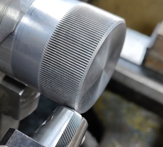
Straight knurling consists of parallel ridges running along the axis of a cylinder. The teeth are oriented circumferentially, creating axial grooves.
Characteristics:
- High directional grip, effective against rotational slip
- Simpler pattern formation and easier alignment
- Common on knobs, thumb wheels, and sleeves where torque transmission is important
Straight knurls typically have a single set of teeth and are less sensitive to diameter-pitch mismatch than diamond patterns but still benefit from proper matching.
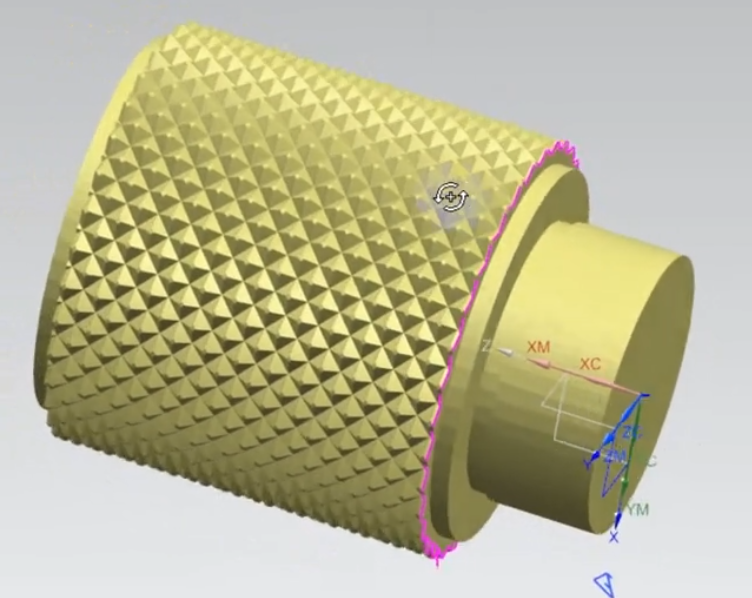
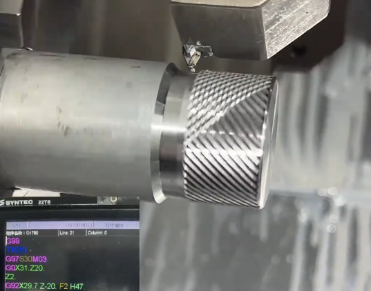
Diamond Knurling
Diamond knurling is produced by crossing two sets of diagonal teeth, forming a regular array of pyramidal peaks.
Characteristics:
- Multi-directional grip and high friction in both axial and circumferential directions
- Common for hand-operated parts such as tool handles, camera controls, and instrument knobs
- Distinctive aesthetic often used for decorative purposes
Diamond knurls can be:
Male (raised) diamonds: Ridges form peaks above the original surface, ideal for maximum grip.
Female (recessed) diamonds: Common in applications where debris accumulation must be minimized or for complementary mating surfaces.
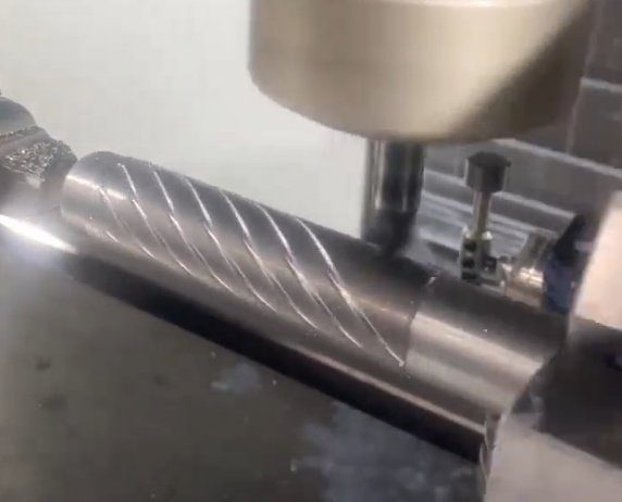
Diagonal Knurling
Diagonal knurling uses a single set of teeth oriented at an angle to the axis. It is essentially one half of a diamond pattern.
Use cases include:
• Visual orientation marks on fasteners and collars
• Matching with a complementary diagonal on a mating component
• Situations where a simple angled texture is desired and cross-rolling is not necessary
Other Specialized Patterns
Some manufacturers provide specialized knurling patterns such as:
• Crossline variants with non-symmetric angles
• Serrated patterns optimized for press-fit retention in plastics or elastomers
• Micro-knurling with very fine pitch for compact components and miniature devices
These patterns obey the same geometric principles but are tailored for specific friction, retention, or cosmetic requirements.
Major Knurling Types by Process
Knurling can be classified by how material is displaced or removed. The two main process categories are form knurling and cut knurling, with several tool configurations in each.
| Process Type | Material Behavior | Typical Machine | Suitable Materials | Key Considerations |
|---|---|---|---|---|
| Form Knurling (Rolling) | Plastic deformation, no chip removal | Engine lathe, CNC lathe | Ductile metals (steel, aluminum, brass) | Higher radial load, diameter growth, need robust fixturing |
| Cut Knurling | Chipping/cutting of material | Engine lathe, CNC lathe | Harder or brittle materials, precision parts | Lower radial load, better surface definition, more parameter control |
| Die-Press Knurling | Forming via press tooling | Presses, stamping equipment | Sheet metal, small cylindrical items | High-volume production, dedicated tooling |
Form Knurling (Roll Knurling)
Form knurling uses hardened roller wheels forced radially into the rotating workpiece, plastically deforming the surface to match the teeth. It is the most common approach on general-purpose lathes.
Key features:
• No intentional chip production; surface material is displaced
• Workpiece diameter increases in the knurled zone
• Requires sufficient machine rigidity and power
• Suitable for medium to coarse patterns and most ductile metals
Form knurling is often preferred for high throughput and robust components where tight dimensional tolerance on the knurled diameter is not critical, or can be accounted for in design.
Cut Knurling
Cut knurling uses specially shaped tool wheels or inserts that cut into the workpiece surface while feeding rather than simply displacing material. The profile is generated by material removal instead of pure plastic deformation.
Advantages:
• Lower radial forces, reduced risk of deflection on slender parts
• Sharper, more precise tooth geometry and cleaner roots
• Reduced tendency to cause work hardening near the surface
• Less sensitivity to exact diameter-pitch match than form knurling
Cut knurling is widely used in precision components, harder alloys, and where accurate pattern replication is required with minimal pattern distortion.
Die-Press and Non-Lathe Knurling Methods
Besides lathe-based knurling, patterns can be produced by pressing or rolling in dedicated equipment:
• Progressive dies or coining dies in stamping operations for sheet or thin-walled parts
• Rotary swaging and rolling machines for continuous production of knurled rods
• Cold heading and forming processes that integrate knurling into the forming cycle of fasteners or pins
These methods are advantageous for large production runs where per-part cycle time and consistency are critical, and where lathe-style processing would be inefficient.
Knurling Tool Designs and Configurations
Knurling tools are assemblies that hold and guide the knurl wheels. Their design directly affects pattern formation, tool life, and machine loading.
Single-Wheel Knurling Tools
Single-wheel tools press one knurl roll into the workpiece. They are simple and compact, commonly used for straight and diagonal patterns.
Characteristics:
• Well suited for external knurling on accessible cylindrical surfaces
• Radial load is applied on one side, tending to deflect the workpiece if not supported properly
• Often used on manual lathes due to ease of setup
Opposed Double-Wheel (Straddle) Tools
Opposed tools mount two knurl wheels that contact the workpiece from opposite sides, balancing radial forces.
Key benefits:
• Reduced bending load on the workpiece, suitable for slender parts
• More uniform deformation and better pattern registration
• Improved dimensional control over knurled diameter
These tools are frequently used for form knurling when machine rigidity or workpiece stiffness are limited.
Cut-Type Knurling Tools
Cut-type tools are designed to position the knurl wheels at a specific lead angle and depth, often with adjustable settings for cutting depth and feed. Tooling may resemble threading tools in their geometry and setup logic.
Typical features include:
• Fine control of radial infeed and axial feed
• Positive rake cutting edges integrated into the knurl profile
• Insert-based systems for rapid replacement of worn cutting wheels
Internal Knurling Tools
Internal knurling is used to texture bores or internal surfaces. Tools may include expanding arbors or radial arms with small knurl wheels.
Considerations:
• Restricted access and chip evacuation for cut knurling
• Tool deflection control due to overhang
• Limited maximum pattern pitch and diameter
Internal knurling is common in bushings, sleeves, and components requiring improved bonding with insert-molded plastics or adhesives.
Knurl Pitch, Diameter Matching, and Pattern Integrity
For form knurling in particular, proper synchronization between workpiece diameter and knurl pitch is necessary to avoid pattern defects.
Pitch and Diameter Relationship
The basic objective is to ensure that an integer number of knurl teeth fit around the workpiece circumference. For a knurl wheel with pitch p, the theoretical ideal diameter D satisfies:
D ≈ (N × p) / π
Where N is an integer number of teeth engaged. In practice, diameters are chosen so that the ratio of circumference to pitch is close to an integer, within an acceptable tolerance that avoids double tracking.
Common Pattern Defects Related to Pitch
• Double tracking: The knurl pattern appears to shift or overlay two sets of teeth, producing irregular diamonds or ridges.
• Incomplete flanks: Under-formed peaks or valleys where the knurl teeth do not re-engage previous impressions correctly.
• Pattern wandering: The diamond or straight ridges do not maintain constant spacing along the length of the knurled area.
These issues are mitigated by careful selection of workpiece diameters, consistent infeed strategy, rigid tooling, and correct alignment of the tool to the workpiece axis.
Recommended Knurling Parameters
Proper choice of speed, feed, and infeed strategy is central to reliable knurling quality. Values vary with material, machine capability, tool type, and knurl pitch.
| Material | Process Type | Surface Speed (m/min) | Feed Rate (mm/rev) | Notes |
|---|---|---|---|---|
| Mild steel | Form knurl | 10–30 | 0.2–0.5 | Moderate pressure, coolant recommended |
| Aluminum alloys | Form knurl | 20–50 | 0.2–0.6 | Avoid excessive pressure to reduce galling |
| Brass | Form knurl | 15–40 | 0.15–0.4 | Good formability, typically clean pattern |
| Alloy steel (pre-hardened) | Cut knurl | 8–20 | 0.1–0.3 | Use cutting fluid, maintain sharp tools |
| Stainless steel | Cut knurl | 8–18 | 0.1–0.25 | Lower speed to limit work hardening |
Infeed Strategies
Radial infeed must be controlled to achieve full tooth depth without overloading the machine or damaging the workpiece.
Typical approaches:
• Single heavy infeed: One substantial plunge to full depth followed by axial feeding. Used in rigid setups with robust workpieces.
• Incremental infeed: Several smaller plunges with intermediate passes to gradually reach full depth. Reduces risk of distortion or chatter.
• Angled infeed (cut knurling): Combination of radial and axial movement to maintain a consistent cutting depth and load.
Coolant and Lubrication
Coolant or lubricants help in:
• Reducing friction between the knurl and workpiece
• Improving surface finish and definition of tooth edges
• Lowering tool and workpiece temperatures
Cut knurling benefits particularly from suitable cutting fluids to carry away chips and prevent built-up edge on the knurl teeth.
Material Considerations for Knurling
The response of a material to knurling depends on its hardness, ductility, and surface condition.
Soft and Ductile Metals
Materials such as aluminum, brass, and low-carbon steels respond well to form knurling, as they tolerate plastic deformation without cracking. Care must be taken to:
• Avoid excessive pressure that can smear the pattern
• Use properly sharpened and clean knurl wheels to prevent galling
• Possibly harden the surface after knurling if wear resistance is required
Hard and Work-Hardening Materials
Stainless steels, high-strength alloys, and hardened materials are often better suited to cut knurling.
Key points:
• Lower surface speeds to control work hardening and heat
• Use robust tooling and rigid setups to maintain pattern geometry
• Prefer cut tools with appropriate rake and clearance angles
Non-Metallic Materials
Knurling can be applied to plastics, elastomers, and composites, particularly for improved bonding and anti-slip surfaces.
Special considerations:
• Reduced pressure to avoid tearing or local overheating
• Coarser patterns for elastomers to maintain function under compression
• Possible use of modified knurl tooth geometries optimized for soft materials
Dimensional and Surface Quality Control
Knurling modifies both diameter and surface texture. Quality control must address both aspects to maintain functional and assembly requirements.
Diameter and Tolerance Management
In form knurling, the finished diameter is larger than the pre-knurled diameter due to material displacement. The exact increase depends on pattern depth and pitch.
Common approaches:
• Turning the shaft to a pre-knurl undersize so that the final knurled diameter meets the required tolerance.
• Specifying a functional tolerance band for the knurled section that allows for deformation-induced variation.
• Measuring diameter at multiple angular positions to check for out-of-roundness caused by uneven forming.
Surface Finish and Pattern Uniformity
Inspection methods include:
• Visual examination for missing teeth, tearing, or double tracking
• Profile measurement using contact or optical instruments to verify tooth height, pitch, and flank angle
• Comparators or replicas for high-volume inspection of repeated knurled parts
Pattern uniformity along the length and around the circumference is crucial for consistent grip and interference behavior in press-fit applications.
Common Practical Difficulties
Typical issues encountered in production include:
• Excessive machine load and chatter when form knurling on light-duty lathes
• Deformation or bending of slender shafts due to unbalanced radial forces
• Rapid wear or chipping of knurl wheels in abrasive or hard materials
• Poor pattern replication when pitch and diameter are not adequately matched
These can be mitigated through appropriate tool selection, use of opposed tools, adjustment of process parameters, and verification of setup alignment.
Applications of Knurling in Industry
Knurling is widely applied in diverse sectors where controlled friction and visual texture are required.
Hand-Operated and Adjustment Components
Examples include instrument knobs, camera controls, medical device adjusters, tool handles, and switches. Diamond or straight knurls are used to provide grip even when operated with gloves or in oily conditions.
Mechanical Coupling and Press Fit Enhancement
Knurled surfaces are frequently used on shafts, pins, and inserts that are overmolded with plastic or pressed into mating components. The textured profile increases mechanical interlock and retention force.
Decorative and Identification Features
Consumer products, luxury tools, and electronic enclosures often use knurling for aesthetic effect combined with tactile feedback. Additionally, selective knurling can provide tactile cues or visual indicators for alignment and orientation.
Best Practices for Reliable Knurling Operations
Reliable knurling depends on controlled process conditions, suitable tooling, and attention to machine capability.
Tool and Machine Setup
Key recommendations:
• Align the knurl tool squarely with the workpiece axis to prevent skewed patterns
• Use appropriate support (tailstock, steady rest) for long or slender parts
• Confirm secure clamping of the knurl wheels to avoid axial play
• Inspect knurl teeth regularly for wear or chipping and replace as necessary
Process Planning and Documentation
Consistent results are achieved by:
• Documenting chosen speeds, feeds, infeed strategy, and coolant usage
• Standardizing on specific knurl pitches and patterns for common part families
• Defining acceptable tolerance ranges for knurled diameters and surface characteristics in drawings and specifications
FAQ
What is knurling?
Knurling is a machining process that creates a patterned texture on the surface of a workpiece, typically using a lathe, to improve grip, aesthetics, or functionality.
What are the main types of knurling patterns?
The most common knurling patterns are straight knurling, diamond knurling, and diagonal knurling, each serving different functional or aesthetic needs.
What are common applications of knurled parts?
Typical applications include control knobs, thumb screws, shafts, rollers, grips, and adjustment components.
What is the difference between form knurling and cut knurling?
Form knurling displaces material using pressure from knurl wheels, increasing the workpiece diameter and requiring higher radial loads. Cut knurling removes material with cutting edges integrated into the knurl, producing sharper patterns with lower radial forces and better suitability for harder materials and precision applications.
How much does knurling increase shaft diameter?
The diameter increase depends on knurl pitch and depth, as well as material properties. As a general guideline, the diameter growth may range from a few tenths of a millimeter for fine knurls to more than 1 mm for coarse patterns. Pre-machining the shaft to an undersized diameter and verifying results on sample parts is the most reliable way to achieve a target final size.
