
Aerospace CNC machining is a primary manufacturing method for structural, propulsion, landing gear, and interior components in aircraft and spacecraft. It provides high dimensional accuracy, repeatability, and material flexibility for both prototype and serial production. This guide explains the technical characteristics, typical applications, materials, process workflows, tolerances, surface finishes, quality control practices, and cost factors specific to aerospace CNC machining.
Core Characteristics of Aerospace CNC Machining
Aerospace CNC machining differs from general industrial machining by its higher precision requirements, stringent documentation, and use of difficult-to-machine alloys and high-performance polymers. The process must ensure traceable, repeatable production of safety-critical parts that operate under high loads, temperature extremes, and corrosive environments.
Precision and Tolerances
Aerospace components often require tighter tolerances than standard industrial parts. Common tolerance ranges include:
- General machined features: ±0.05 mm to ±0.01 mm
- Critical bores, bearing seats: ±0.005 mm to ±0.002 mm
- Flatness/parallelism for mounting surfaces: 0.02 mm to 0.005 mm per 100 mm
Such tolerances are maintained through rigid machine structures, thermal stability, high-resolution encoders, and closed-loop control systems.
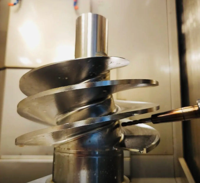
Multi-Axis Capability
Complex aerodynamic shapes, internal channels, and integrated features require multi-axis machining. Typical capabilities:
- 3-axis CNC milling: simple prismatic parts, brackets, flanges
- 4-axis CNC milling: turbine disks, impellers, parts with radial features
- 5-axis CNC milling: blisks, blades, structural nodes, housings with undercuts
On turning centers, Y-axis and sub-spindle configurations enable complete machining in one clamping, reducing tolerance stack-up and setup time.
Repeatability and Process Stability
Production of aerospace parts often spans years, with periodic batch orders. Process stability is supported by:
1) Standardized setups: Documented fixtures, tooling, and programs ensure consistent part positioning and clamping conditions.
2) Controlled cutting parameters: Tool libraries with pre-validated feeds, speeds, and depths of cut for specific materials maintain consistent surface integrity and tool life.
Machine capability indices (Cp, Cpk) are monitored for critical dimensions to demonstrate process capability over time.
Key Aerospace Components Manufactured by CNC
CNC machining is used across multiple aerospace subsystems, from airframe to propulsion to interiors. Below are typical part types and their characteristics.
Airframe and Structural Components
Airframe parts must provide high strength and stiffness at minimal weight, often with thin walls and complex internal pockets.
Typical parts include:
- Wing ribs, spars, and stringers
- Fuselage frames and bulkheads
- Structural brackets, fittings, and joints
Technical characteristics:
Wall thickness often ranges from 0.8 mm to 3.0 mm in aluminum, with larger structural members featuring local reinforcements where loads are concentrated. Deep pockets with high aspect ratios require optimized roughing and finishing strategies to avoid deformation.
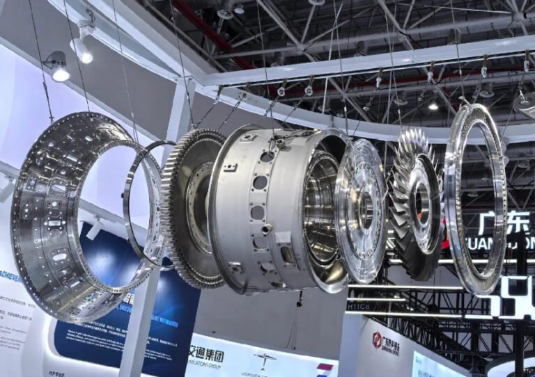
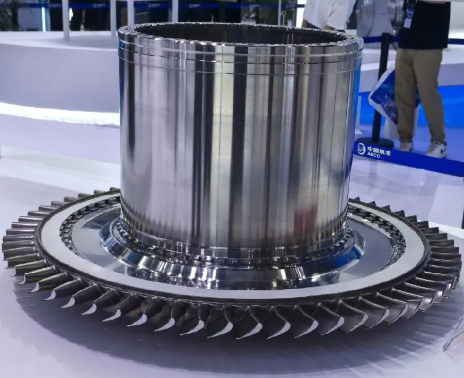
Engine and Propulsion Components
Engine parts demand high-temperature resistance, fatigue strength, and precise geometry for aerodynamic and thermodynamic efficiency.
Common CNC-machined engine parts:
- Compressor and turbine blades
- Blisks (bladed disks)
- Casing components, bearing housings, and gear housings
- Fuel system components and injector bodies
In many cases, 5-axis simultaneous machining is used to profile blades, manage complex shroud geometries, and maintain tight chord and twist tolerances. Superalloys and titanium alloys require low cutting speeds, high cutting forces, and wear-resistant tooling.
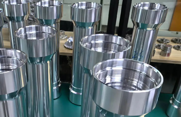
Landing Gear and Actuation Components
Landing gear elements are subjected to high impact loads and repeated cyclic stresses.
Representative components include:
- Main and nose gear cylinders and pistons
- Axles, trunnions, and torque links
- Actuator housings and shafts
These parts are often made from high-strength steels and titanium, with critical surfaces such as bearing seats, sealing surfaces, and threads requiring fine tolerances and controlled surface roughness.
Cabin, Interior, and Avionics Components
While structural requirements are lower than for primary structures, interior and avionics components still demand high reliability and effective integration.
Typical parts include:
- Instrument panels and bezels
- Avionics housings and heat sinks
- Seat components, armrests, and mounting brackets
These components frequently use aluminum, magnesium, engineered plastics, and composite inserts. Dimensional tolerances are combined with cosmetic requirements, especially for visible surfaces.
Materials Used in Aerospace CNC Machining
Aerospace CNC machining covers a wide range of metallic and non-metallic materials, each selected for specific strength, weight, temperature, and corrosion-resistance requirements.
Aluminum Alloys
Aluminum is widely used for airframe structures and interior components due to its low density, machinability, and good strength-to-weight ratio.
Common aerospace aluminum alloys and characteristics include:
| Alloy | Typical Applications | Key Properties |
|---|---|---|
| 2024-T3/T4 | Wing and fuselage skins, structural fittings | High strength, good fatigue resistance, lower corrosion resistance |
| 6061-T6 | Fixtures, non-critical structures, interior parts | Good strength, excellent machinability and weldability |
| 7075-T6/T73 | Highly stressed structural parts, landing gear components | Very high strength, moderate corrosion resistance, good machinability |
Cutting speeds for aluminum can be very high, often in the range of 300–800 m/min depending on tool material and coating, with high chip loads to maximize material removal rates.
Titanium Alloys
Titanium alloys are used where high strength, low density, and corrosion resistance are essential, particularly near hot zones or where weight savings are crucial.
Common alloys and uses:
- Ti-6Al-4V (Grade 5): General structural components, engine mounts, landing gear components
- Ti-6Al-4V ELI: Components requiring improved fracture toughness
- Beta titanium alloys: Springs, high-strength fasteners
Titanium machining requires lower cutting speeds (often 30–80 m/min for carbide tools), high coolant flow, and rigid setups to control deflection. Heat generation and tool wear are significant. Thin-walled titanium structures must be machined with optimized toolpaths to minimize distortion and vibration.
Nickel-Based Superalloys
Nickel-based superalloys are used for high-temperature engine parts such as turbine blades, disks, and combustor components.
Representative alloys:
- Inconel 718: Disks, shafts, engine mounts, high-temperature fasteners
- Inconel 625: Exhaust components, hot gas path parts
- Waspaloy and similar alloys: Highly stressed, high-temperature turbine components
These alloys maintain mechanical properties at temperatures exceeding 600 °C but are challenging to machine. Cutting speeds may range from 15–60 m/min, with low radial depths of cut and aggressive cooling to limit tool wear and preserve surface integrity. Tool life is monitored closely, and adaptive toolpath strategies are used to manage heat and vibration.
Steels and Stainless Steels
Aerospace applications use both carbon steels and stainless steels for landing gear, fasteners, shafts, and structural elements.
Common materials:
- 300M and 4340 steels: Landing gear, bolts, highly loaded structural elements
- 17-4PH stainless: Shafts, fittings, components with corrosion and strength requirements
- 15-5PH and 13-8Mo: Critical corrosion-resistant structural parts
Heat treatment and machining sequence must be coordinated to maintain dimensional stability and required mechanical properties. Grinding may follow turning or milling for critical bearing surfaces.
Engineered Plastics and Composite-Related Machining
Engineering plastics and composite-related machining include operations on polymer components and metallic inserts used in composite assemblies.
Typical materials:
- PEEK and carbon fiber reinforced PEEK: High-temperature, high-strength interior and structural components
- PTFE and fluoropolymers: Seals, insulation, low-friction components
- Phenolic materials: Insulating and structural components
Machining plastics requires careful control of cutting speeds, tool geometry, and clamping to avoid melting, burrs, or distortion. For composite-related work, CNC machining often drills or routes cured composite parts with diamond-coated tools to minimize delamination.
Dimensional Control, Tolerances, and Surface Quality
Dimensional and geometric accuracy are critical for assembly, vibration performance, load transfer, and sealing. Aerospace CNC machining addresses multiple categories of tolerances and surface conditions.
Dimensional and Geometric Tolerances
Drawings typically use GD&T (Geometric Dimensioning and Tolerancing). Common requirements:
- Position tolerance for holes and dowels: 0.02–0.1 mm depending on function
- Runout of rotating components: 0.01–0.05 mm TIR
- Perpendicularity, parallelism, and concentricity within 0.01–0.05 mm
To maintain such tolerances, CNC programs integrate probing cycles to verify datum locations and compensate for small setup deviations. Thermal effects are controlled through stable room temperatures and machine compensation systems.
Surface Roughness Requirements
Surface finish requirements vary by function:
- General structural surfaces: Ra 1.6–3.2 µm
- Sealing surfaces and bearing seats: Ra 0.2–0.8 µm
- Aerodynamic surfaces: Ra 0.4–1.6 µm, with tight control over waviness
Surface roughness is verified using contact profilometers or non-contact optical devices. Finishing processes such as grinding, superfinishing, or lapping may be applied after CNC machining when necessary.
Surface Integrity and Subsurface Effects
Beyond roughness, surface integrity includes residual stress, microhardness, and metallurgical condition. Excessive heat or tool wear can cause microcracks, work hardening, or structural changes in sensitive alloys. Cutting parameters, tool condition, and coolant delivery are controlled to maintain acceptable surface integrity, especially for fatigue-critical components.
Process Workflow in Aerospace CNC Machining
A structured process workflow supports consistent manufacturing quality and traceability from design to finished part.
Design Review and Manufacturability Analysis
Before machining begins, engineers review 3D models and drawings for manufacturability. Typical checks include:
- Access for cutting tools and required tool lengths
- Minimum wall thickness and pocket design to prevent deformation
- Availability of suitable material stock and blank sizes
Possible adjustments are defined within the constraints of certification and functional requirements, such as adding machining reliefs or redesigning non-critical features to simplify toolpaths.
CAM Programming and Toolpath Strategy
CAM software is used to generate CNC programs from CAD models. Considerations include:
- Selection of cutting strategy (e.g., high-speed machining, trochoidal milling)
- Tool type selection (end mills, drills, reamers, form tools) and toolpath optimization
- Collision avoidance in multi-axis operations and fixture clearance
Toolpaths are simulated to check for collisions, over-travel, and excessive tool engagement. For complex 5-axis work, post-processors create machine-specific code with synchronized axis movements.
Fixture Design and Part Clamping
Reliable fixtures are crucial, especially for thin-walled or long, slender parts. Fixture design addresses:
- Proper support and clamping to minimize deflection
- Repeatable locating features tied to datum structures
- Clearance for cutting tools and chip removal
Modular fixtures may be used for families of parts, while dedicated fixtures are common for high-volume or high-precision components. Vacuum fixtures or soft jaws can be used for thin plate and skin components.
Machining Operations and In-Process Inspection
Machining steps typically follow a defined sequence:
- Roughing operations remove bulk material with high material removal rates.
- Semi-finishing operations leave a controlled allowance for finishing, stabilizing remaining stresses.
- Finishing operations achieve final tolerance and surface finish with lower cutting forces.
In-process inspections using machine probes or external gauges verify critical dimensions mid-process. Deviations may trigger automatic tool offsets or adjustments to maintain tolerance.
Post-Machining Operations
After CNC machining, components often undergo additional processes such as:
- Deburring and edge finishing
- Heat treatment (if not performed prior to final machining)
- Surface finishing and coating
- Final inspection and marking for traceability
Post-process steps are integrated into the overall production plan to avoid dimensional changes and preserve surface integrity.
Surface Finishes and Protective Coatings
Aerospace parts require controlled surface finishes and protective layers to ensure corrosion resistance, wear resistance, and joint performance.
Mechanical and Chemical Surface Finishes
Common mechanical and chemical finishing processes after CNC machining include:
- Bead blasting or shot peening: For stress improvement and surface texturing.
- Mechanical polishing: For cosmetic or low-friction surfaces.
- Chemical etching: For surface preparation before bonding or coating.
Shot peening parameters such as intensity and coverage are controlled for fatigue-critical parts, and process verification is documented.
Anodizing and Conversion Coatings
Aluminum parts often receive anodizing or conversion coatings for corrosion protection and, in some cases, improved paint adhesion.
Typical treatments:
- Type II anodizing: General corrosion protection and color coding.
- Type III hard anodizing: Wear-resistant surfaces for sliding and bearing sections.
- Chromate conversion coatings (e.g., Alodine-type processes): Thin, conductive layers for bonding and electrical continuity.
Coating thickness ranges are controlled, often between 5–25 µm, depending on the application and specification.
Plating, Painting, and Special Coatings
Other coatings used with machined aerospace parts include:
- Electroless nickel plating: Corrosion and wear protection with uniform thickness
- Cadmium or zinc-nickel plating: Corrosion protection for fasteners and steel parts
- Specialized thermal barrier coatings (TBCs): For high-temperature engine components
Coating selection and sequence are coordinated with machining to avoid compromising dimensional accuracy or creating unwanted residual stresses.
Quality Control and Certification Requirements
Quality assurance in aerospace CNC machining is structured around standardized systems and detailed traceability. Parts often support flight safety and require documented conformity at every stage.
Quality Management Systems and Documentation
Many aerospace manufacturers work under standards such as AS9100 and ISO 9001. Key elements include:
- Controlled documentation of procedures, work instructions, and inspection plans
- Traceability of materials, processes, and inspection results to each part and batch
- Periodic audits of processes and equipment
Documentation may include certificates of conformity, material certificates, heat treatment reports, and coating process records.
Inspection Methods and Measurement Equipment
Inspection of aerospace parts uses a combination of contact and non-contact methods:
- CMM (Coordinate Measuring Machines) for high-accuracy measurement of complex geometry
- Optical or laser scanning systems for free-form surfaces and blade profiles
- Profilometers for surface roughness measurement
- Gauges (plug, ring, air gauges) for critical bores and fits
Measurement uncertainty is quantified, and calibration schedules are maintained for all instruments. For certain critical parts, 100% inspection is performed; for others, sampling plans follow statistical process control techniques.
Traceability and Part Identification
Traceability links each finished part to its raw material batch, process steps, and inspection results. Part identification may be achieved by:
- Laser marking
- Dot peen marking
- Engraving or stamping on designated, non-critical areas
This ensures that in the event of any issue, affected components can be rapidly identified and segregated.
Cost Drivers in Aerospace CNC Machining
The total cost of CNC machined aerospace parts is influenced by material, complexity, precision, lot size, and quality requirements. Understanding the primary cost drivers helps to align design and production planning with budget expectations.
Material Costs and Utilization
High-performance alloys such as titanium and nickel-based superalloys have significantly higher raw material costs than standard steels or aluminum. Additionally, many aerospace parts are machined from solid billets or forgings, resulting in high buy-to-fly ratios, sometimes 5:1 or higher for heavily pocketed structures.
Material-saving strategies include:
- Using near-net-shape forgings or castings where feasible
- Optimizing nesting of parts in plate or bar stock
- Reducing unnecessary stock allowances in design, as long as manufacturing tolerances are achievable
Machine Time and Cycle Time
Machine time is often the largest contributor to production cost. Factors that impact cycle time include:
- Number of operations and setups
- Material removal volume and allowance
- Required surface finish and tolerance levels
Cycle time can be reduced by using high-speed machining, optimized toolpaths, multi-axis operations that reduce repositioning, and automated pallet systems for lights-out production.
Tooling and Consumable Costs
Tooling costs cover cutting tools, toolholders, workholding fixtures, and probes. Difficult-to-machine materials consume tools more rapidly, increasing consumable usage. Cost considerations include:
- Frequency of tool changes and tool life per part
- Cost of specialized tools (e.g., special form cutters, diamond-coated drills)
- Development and fabrication of dedicated fixtures, particularly for complex thin-walled parts
Standardized tooling and modular fixtures help distribute cost over multiple part numbers and batches.
Programming, Setup, and Non-Recurring Engineering (NRE)
Complex aerospace parts require significant upfront engineering effort:
- CAM programming and toolpath optimization
- Fixture and workholding design and verification
- Machining trials and process validation runs
These activities generate non-recurring engineering costs, which are distributed across the expected part volume. Low-volume or prototype parts may therefore have a higher cost per piece than high-volume production items.
Inspection and Quality Assurance Costs
Inspection of aerospace components often takes substantial time and specialized equipment. High requirements for dimensional verification, documentation, and traceability increase labor and overhead costs.
Influencing factors include:
- Percentage of features requiring CMM measurement
- Need for 100% inspection versus sampling
- Additional tests such as non-destructive testing (NDT) when specified
Automation of inspection steps and integration of in-process measurement can reduce overall cost but may require additional initial investment.
Typical Cost Ranges and Comparative Overview
Cost per aerospace CNC machined part varies widely based on size, material, complexity, and volume. While exact figures depend on specific requirements and regions, the relative cost relationships can be indicated as follows.
| Part Type | Material | Relative Cost Level | Main Cost Drivers |
|---|---|---|---|
| Simple bracket | Aluminum 6061/7075 | Low to Medium | Short cycle times, moderate material cost, minimal setups |
| Thin-walled structural rib | Aluminum 7075 | Medium | Long machining time, high material removal, fixturing complexity |
| Engine blade or blisk segment | Titanium or superalloy | High | Difficult material, 5-axis machining, tight tolerances, heavy inspection |
| Landing gear cylinder | High-strength steel | Medium to High | Large volume, precision bores, heat treatment, grinding |
| Avionics housing | Aluminum or magnesium | Medium | Multiple internal features, threads, sealing surfaces, finishing |
The relative cost level reflects combined effects of raw material pricing, machining difficulty, precision requirements, and inspection complexity.
Practical Considerations and Common Issues
Aerospace CNC machining must address several practical issues that can affect part quality, delivery time, and cost.
Thin-Walled Features and Deformation
Many aerospace structures rely on thin walls and deep pockets to reduce weight. Common issues include chatter, local distortion, and dimensional drift after unclamping. Mitigation techniques include:
- Optimized toolpaths with lower radial engagement and multiple light passes
- Use of support ribs during machining, later removed in finishing steps
- Controlled clamping forces and balanced support of critical areas
Process planning must consider the order of operations to minimize residual stresses and deformation, especially in high-strength alloys.
Heat Management in Hard-to-Machine Alloys
Superalloys and titanium generate high cutting temperatures and specific cutting forces. Without effective heat management, tool wear and surface integrity issues arise. Considerations include:
- High-pressure coolant delivery to the cutting zone
- Use of coated carbide tools or ceramics for specific operations
- Conservative cutting parameters tuned to tool and material limits
Continuous monitoring of tool wear and scheduled tool changes prevent defects in critical surfaces.
Burr Formation and Deburring
Burr formation around holes and edges, especially in aluminum and titanium, is a recurring issue. Effective deburring is essential to prevent assembly problems and potential crack initiation points.
Approaches include:
- Toolpath strategies that minimize burrs, such as climb milling and optimized entry/exit
- Use of deburring tools in the CNC process for confined locations
- Manual or automated deburring processes after machining
Deburring requirements should be integrated into time estimates and inspection criteria to avoid surprises in lead time and cost.
