
In CNC machining, “precision” and “accuracy” are often used as if they mean the same thing, but they describe different performance characteristics. Understanding the difference is essential for specifying tolerances, selecting suppliers, programming machines, and interpreting inspection reports.
Core Definitions: Precision, Accuracy, and Repeatability
Precision and accuracy are statistical concepts applied to machining results. They describe where measured dimensions land relative to each other and relative to the target value.
Accuracy
Accuracy describes how close a measurement or machined feature is to its intended or nominal value. In CNC machining, this typically refers to how close the actual dimension is to the CAD or drawing specification.
- High accuracy: Average of the measured values is very close to the nominal dimension.
- Low accuracy: Measured values are systematically shifted away from the nominal (systematic error or bias).
Example: A shaft specified at 20.000 mm is machined and measured at 19.985, 19.986, 19.984, 19.985 mm. The average is 19.985 mm, which is 0.015 mm smaller than the target. This process has a bias of −0.015 mm (accuracy error) even though the results are clustered tightly.
Precision
Precision describes how tightly a group of measurements or machined dimensions cluster together, regardless of how close they are to the target value.
- High precision: Low variation between parts; results are very consistent.
- Low precision: Large scatter; results fluctuate significantly from part to part.
Using the same example, the four measurements (19.985–19.986 mm) are very close to each other, indicating high precision.
Repeatability and Reproducibility
Two additional terms are important for a full understanding:
- Repeatability: The ability of the same machine, operator, setup, and conditions to produce the same measurement for the same part feature over multiple trials.
- Reproducibility: The variation in measurements when conditions change, such as different operators, fixtures, or inspection devices.
In practice, repeatability is closely related to precision. A process with poor repeatability cannot be precise.
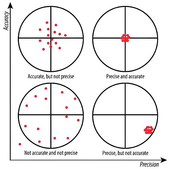
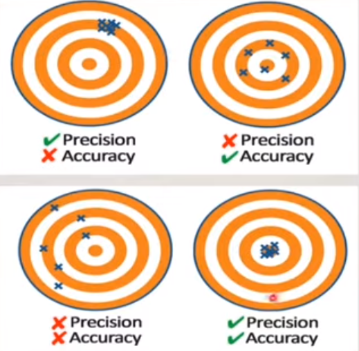
Visualizing Precision vs Accuracy in CNC Machining
The classic way to visualize precision and accuracy is with a target and bullet holes, but in machining a more practical view is a capability plot of measured dimensions versus the nominal value and tolerance limits.
| Case | Accuracy | Precision | Typical Measurement Pattern | Implication |
|---|---|---|---|---|
| High accuracy, high precision | High (mean near nominal) | High (low scatter) | Measurements tightly clustered around nominal | Ideal machining process with stable outputs and minimal bias |
| High accuracy, low precision | High (mean near nominal) | Low (high scatter) | Measurements scattered widely but averaged near nominal | Many parts may fail tolerance despite small average error |
| Low accuracy, high precision | Low (mean offset from nominal) | High (low scatter) | Measurements tightly clustered but shifted away from nominal | Simple offset correction can often fix the problem |
| Low accuracy, low precision | Low | Low | Measurements scattered and mean far from nominal | Requires both calibration and process improvement |
How Precision and Accuracy Relate to Tolerances
Tolerances translate functional requirements into quantitative limits that CNC machinists must meet. Precision and accuracy determine whether the process can consistently produce parts within these limits.
Nominal Dimensions and Tolerance Zones
Every critical dimension on a drawing has:
- Nominal size (target value).
- Upper and lower tolerance limits (e.g., 20.000 ± 0.010 mm → 19.990–20.010 mm).
Accuracy is about where the average of measurements falls relative to this zone. Precision is about how tightly the measurements fit within the zone.
Symmetric vs Asymmetric Tolerances
Many CNC drawings use symmetric bilateral tolerances (±). Others apply unilateral tolerances (e.g., +0.000 / −0.020 mm). In either case:
• A high-precision but inaccurate process may consistently sit near one tolerance boundary, risking out-of-spec parts if conditions change slightly.
• A high-accuracy, low-precision process may produce some parts at each boundary and some outside, making capability unpredictable.
Relation to Functional Requirements
Functional requirements dictate how strict tolerances must be. For instance:
• Sliding fits and bearing bores require controlled clearances; both precision and accuracy are critical for mating parts.
• Non-critical cosmetic features mainly require adequate accuracy to avoid visibly wrong geometries; precision is less critical.
Machine Capability vs Process Capability
Precision and accuracy are influenced by both the machine tool and the entire machining process. A highly capable machine cannot compensate for unstable process conditions, and vice versa.
Machine Tool Accuracy and Precision
Key machine specifications related to accuracy and precision include:
- Linear positioning accuracy (e.g., ±0.005 mm across the travel).
- Repeatability (e.g., ±0.002 mm for axis repositioning).
- Backlash compensation performance.
- Thermal stability and thermal compensation systems.
Machine accuracy describes how closely commanded positions match actual positions. Machine precision relates to how consistently the axis can return to commanded locations.
Even if a machine has high inherent accuracy, issues such as insufficient warm-up, mechanical wear, or inadequate calibration can introduce systematic errors, affecting dimensional accuracy of parts.
Process Capability (Cp, Cpk)
Process capability indexes quantify how well an actual machining process can meet tolerance requirements over time. Although they are statistical, they are directly tied to practical precision and accuracy.
Common indicators:
- Cp: Compares the width of the tolerance to the spread of the process (precision). It assumes the process mean is centered.
- Cpk: Considers both spread and centering (precision and accuracy). It is the minimum of the capability relative to each tolerance limit.
Cp is influenced mainly by variation (precision). Cpk is influenced by both variation (precision) and mean shift (accuracy). High Cp with low Cpk usually indicates a precise but inaccurate process (consistent but off-center).
Typical Numerical Ranges in CNC Machining
Different CNC equipment and setups achieve different levels of precision and accuracy. The following table shows indicative ranges (actual performance depends on specific machines, conditions, and materials):
| Machine / Setup Type | Typical Dimensional Accuracy | Typical Precision (Part-to-Part Variation) | Common Tolerance Capability |
|---|---|---|---|
| General-purpose 3-axis CNC mill (standard shop) | ±0.025–0.050 mm | ±0.010–0.030 mm | ±0.050–0.100 mm on most features |
| High-end 3/5-axis machining center with thermal control | ±0.005–0.015 mm | ±0.003–0.010 mm | ±0.010–0.020 mm on precision features |
| CNC turning center (standard) | ±0.010–0.020 mm | ±0.005–0.015 mm | ±0.020–0.050 mm on diameters |
| Precision CNC lathe for tight tolerance work | ±0.003–0.010 mm | ±0.002–0.005 mm | ±0.005–0.015 mm on critical diameters |
| CNC router for plastics/wood | ±0.100–0.250 mm | ±0.050–0.150 mm | ±0.150–0.300 mm on general features |
These ranges show that precision (tight clustering) is usually better than absolute accuracy when the process is stable and well controlled. Fine-tuning tool offsets and compensation can then bring the process mean to the nominal value.
Sources of Error Affecting Precision and Accuracy
Different error sources influence precision and accuracy in different ways. Some cause random variation (affecting precision), while others create systematic shifts (affecting accuracy).
Mechanical Errors
Mechanical aspects of the machine and fixturing contribute to dimensional deviations:
- Backlash and axis play: Creates position error during reversal, affecting both accuracy and precision.
- Ball screw pitch error: Leads to scale errors over travel, primarily affecting accuracy.
- Guideway wear: Can introduce variable friction and micro-movements, reducing precision.
- Spindle runout: Affects circularity and small-feature dimensions, often impacting precision.
Thermal Effects
Temperature changes cause expansion and contraction of machine components, fixtures, tools, and workpieces:
- Machine structure heating: Can shift axes alignment and zero positions (accuracy issue).
- Workpiece heating during cutting: Alters dimensions during machining, influencing both accuracy and precision.
- Ambient temperature fluctuation: Causes drift over time, typically seen as slow accuracy changes.
Thermal compensation systems and controlled environments are typical methods to mitigate these effects in high-precision machining.
Tooling-Related Errors
Cutting tools directly shape the workpiece, so their condition strongly affects dimensions:
- Tool wear: Gradually changes effective tool size or edge position, causing accuracy drift if not compensated.
- Tool deflection: Under cutting load, tools bend, creating dimensional error dependent on cutting conditions (both accuracy and precision).
- Toolholder runout: Creates eccentric cutting, influencing bore size, surface quality, and precision.
Workholding and Fixturing Errors
Fixturing determines the part’s position and rigidity:
- Clamping distortion: Flexible parts may deform under clamping force and relax after unclamping, affecting accuracy.
- Location repeatability: Poorly controlled locating surfaces or worn locators reduce precision.
- Stack-up of fixture components: Multiple interfaces can introduce misalignment, primarily affecting accuracy.
Programming and Coordinate Errors
Even with an ideal machine, programming errors can degrade results:
- Incorrect tool length or diameter offsets: Shift all related dimensions, an accuracy issue.
- Incorrect workpiece zero (work offset): Systematic shift of all programmed features.
- Interpolation errors and CAM output resolution: Can affect curve accuracy, especially in freeform surfaces.
Measurement and Inspection Errors
Inspection must be more accurate and precise than the machining process it evaluates. Common issues include:
- Inadequate gauge accuracy relative to tolerance.
- Operator-dependent measurement variation in manual measurements.
- Temperature differences between machining and inspection environments.
Measurement errors can misrepresent actual precision and accuracy, leading to incorrect conclusions about process performance.
Impact on Geometric Dimensioning and Tolerancing (GD&T)
GD&T defines how part features may deviate from perfect geometry while still fulfilling their functional role. Precision and accuracy directly affect the ability to meet geometric tolerances.
Form and Profile Tolerances
Features such as straightness, flatness, circularity, and profile of a surface are primarily related to consistency along a feature, so they are more sensitive to precision:
- Poor precision leads to surfaces or edges that deviate in an uncontrolled way.
- Accuracy influences how the feature sits relative to nominal geometry but does not change internal variation patterns.
Orientation and Location Tolerances
Features such as position, parallelism, perpendicularity, and concentricity depend on how accurately features are aligned and placed relative to datum references:
- Systematic setup errors, incorrect datums, and misaligned fixtures degrade accuracy of locations and orientations.
- Process variation (e.g., tool deflection differences, inconsistent clamping) reduces precision of feature placement.
High-precision machining reduces scatter of geometric deviations, while high accuracy ensures the average feature location and orientation are correct relative to the datum structure.
Precision vs Accuracy in CNC Quality Control
Quality control in CNC machining uses measurement data to quantify and improve both precision and accuracy. The way measurements are analyzed reveals which aspect needs correction.
Using Statistical Data
From repeated measurements of a critical dimension, two key metrics are usually examined:
- Mean (average) of the measurements: Indicates accuracy relative to nominal.
- Standard deviation or range: Indicates precision (spread) of the process.
If the mean is far from nominal but variation is low, adjusting offsets or calibrating the machine typically improves accuracy. If the variation is large, process stability must be improved first.
Control Charts and Monitoring
Control charts are used to track machining processes over time:
- X̄ charts (mean): Monitor accuracy drift.
- R or σ charts (range or standard deviation): Monitor precision changes.
A control chart will clearly show if the process is stable but off-target (accuracy problem) or unstable with high variation (precision problem).
Practical Pain Points in CNC Projects
In real projects, misunderstanding precision and accuracy often leads to unnecessary cost, rework, and scrap.
Overly Tight Tolerances Without Capability Analysis
Setting very tight tolerances without confirming the machine and process capability can cause:
- Excessive rejection rates due to insufficient precision.
- Multiple adjustment iterations to chase accuracy and reduce scrap.
- Higher inspection workload and measurement costs.
Misinterpreting Inspection Results
Common issues include:
- Assuming a small average deviation means the process is good, despite large scatter (precision problem hidden by acceptable accuracy).
- Declaring the process unstable when only a systematic bias exists that could be corrected through offsets or calibration.
Supplier Communication Gaps
When specifying requirements to machining suppliers, not clearly distinguishing between precision and accuracy can result in misunderstandings:
- Suppliers may meet mean dimensional targets but with inadequate repeatability.
- Or they may maintain tight clustering while offsetting dimensions to compensate for measurement or setup errors.
How to Improve Precision in CNC Machining
Improving precision means reducing random variation between parts or within features. Focus is placed on stabilizing the process and eliminating sources of inconsistency.
Stabilizing the Machine and Environment
- Maintain consistent machine warm-up routines to minimize thermal fluctuations.
- Use controlled ambient temperature where feasible.
- Schedule preventive maintenance to address wear before it affects repeatability.
Optimizing Tooling and Cutting Conditions
- Select rigid toolholders and appropriate tool overhang to limit deflection.
- Balance cutting parameters to minimize vibration and chatter.
- Standardize cutting conditions for repeated work to improve repeatability.
Improving Workholding Consistency
- Use precise locating features and hard stops for repeatable setup.
- Design fixtures to distribute clamping forces and minimize distortion.
- Clean contact surfaces regularly to avoid chips affecting position.
Standardizing Operating Procedures
- Document setup and measurement procedures.
- Train operators to follow consistent practices in loading, measuring, and adjusting.
- Reduce unnecessary adjustments that introduce variation.
How to Improve Accuracy in CNC Machining
Improving accuracy means reducing systematic deviation between the process mean and the target value. This often involves calibration, offsets, and geometric corrections.
Calibration and Compensation
- Perform machine geometry checks (e.g., laser interferometry for linear axes, ballbar tests for circularity).
- Apply axis compensation tables provided by the control to correct scale and straightness errors.
- Regularly calibrate probing systems, tool setters, and measurement instruments.
Offset Optimization
- Use tool length and diameter offsets derived from accurate measurements.
- Adjust workpiece offsets (work coordinates) to align machining with actual part location.
- Review offsets after thermal stabilization of the machine for consistent accuracy.
Model and Program Integrity
- Verify that CAM post-processor outputs match the machine’s kinematics and control specifics.
- Ensure that the CAD model reflects the latest design revision.
- Check for unit mismatches or scaling errors between CAD, CAM, and CNC control.
Closed-Loop Feedback with Probing
- Use in-machine probing to locate the workpiece and update offsets.
- Check critical features and apply corrections mid-process when possible.
- Implement adaptive machining strategies based on measured deviations.
Balancing Precision, Accuracy, and Cost
Achieving very high precision and accuracy usually increases cost through more advanced equipment, tighter environmental control, higher inspection effort, and longer cycle times.
Defining Realistic Requirements
- Base tolerances on functional and assembly requirements, not arbitrary values.
- Evaluate how much variation and mean shift can be tolerated without impacting performance.
- Consider separate tolerance zones for critical and non-critical features to optimize cost.
Matching Process Capability to Requirements
- Select machine tools and fixtures appropriate to the required tolerance class.
- Use pilot runs and capability studies to confirm that Cp and Cpk align with quality targets.
- Adjust design tolerances or process strategies if capability is insufficient.
Quality vs Throughput Considerations
- High-speed machining may increase throughput but can affect precision if not controlled.
- Multiple finishing passes improve accuracy and precision but extend cycle time.
- Inline measurement and adaptive correction improve accuracy but add to process complexity.
Key Takeaways for CNC Engineers and Purchasers
The distinction between precision and accuracy has practical consequences in CNC machining:
- Precision refers to consistency; accuracy refers to closeness to the target.
- High precision with low accuracy indicates a stable but biased process; offsets or calibration can often correct it.
- High accuracy with low precision indicates a process that occasionally hits the target but with large scatter, leading to unpredictable quality.
- Both precision and accuracy must be adequate relative to the specified tolerances and functional requirements.
Focusing on process stabilization (precision) first and then eliminating bias (accuracy) is a systematic way to improve CNC machining performance and reduce scrap and rework.
