
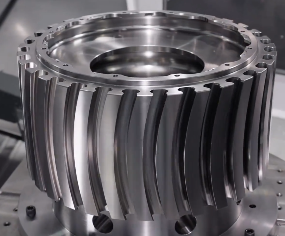
Precision CNC machining is widely used to manufacture complex components that must meet extremely tight dimensional tolerances and high geometric accuracy. These requirements are critical in industries such as aerospace, medical devices, automotive powertrain, semiconductor equipment, optics, robotics, and instrumentation, where any deviation can affect performance, reliability, or safety.
This article explains in detail how modern CNC machining systems achieve and maintain tight tolerances, covering machine design, cutting tools, fixtures, programming, process parameters, environmental control, metrology, and quality assurance practices.
About Tolerances and Accuracy in CNC Machining
To understand how CNC machining achieves tight tolerances, it is essential to clearly define the key dimensional concepts used in precision manufacturing.
Dimensional Tolerance
Dimensional tolerance is the allowable variation in a part feature size around its nominal value. It is typically expressed as a plus/minus value (e.g., 10.000 ± 0.005 mm) or as an upper and lower limit.
Commonly referenced ranges in CNC machining include:
- General machining: ±0.05 mm (±0.002 in)
- Precision machining: ±0.01 mm (±0.0004 in)
- High-precision machining: ±0.005 mm (±0.0002 in) or tighter
The achievable tolerance depends on material, geometry, machine capability, process stability, and inspection method. Tighter tolerances require stricter control of each contributing factor.
Accuracy vs. Repeatability vs. Resolution
Three related but distinct terms describe machine performance:
- Accuracy: How close a measured value is to the true or nominal value (e.g., how close the actual hole diameter is to the intended size).
- Repeatability: The machine’s ability to return to the same position under the same conditions (e.g., running the same program multiple times and obtaining the same dimensions).
- Resolution: The smallest increment of motion that the control system can command or measure (e.g., 0.0001 mm per encoder pulse).
High resolution alone does not guarantee high accuracy; it must be combined with precise mechanical construction, proper calibration, and compensation.
Geometric Tolerances and GD&T
Modern precision requirements are often specified using geometric dimensioning and tolerancing (GD&T). These controls describe not only size but also shape, orientation, and location of features.
Typical GD&T symbols controlled by CNC machining include:
- Form: straightness, flatness, circularity, cylindricity
- Orientation: parallelism, perpendicularity, angularity
- Location: position, concentricity, symmetry
- Runout: circular runout, total runout
Achieving geometric tolerances often requires multi-axis machining, precise fixturing, and carefully planned process sequences to control cumulative error and distortion.
Machine Tool Design Factors Enabling High Accuracy
The inherent design and construction of the CNC machine tool form the foundation of achievable accuracy. No amount of compensation or adjustment can fully overcome fundamental mechanical limitations.
Machine Structure and Rigidity
High-precision CNC machines use robust and carefully engineered structures to minimize elastic deformation under cutting loads. Common characteristics include:
Machine base and column:
- Materials: cast iron, polymer concrete, or heavily ribbed steel structures for high stiffness and damping
- Finite element analysis (FEA)-based design to optimize rigidity and natural frequencies
Guideway systems:
- Linear guideways or box ways with large contact areas and high load capacity
- Preloaded roller or ball guides to minimize backlash and compliance
Higher stiffness reduces deflection due to cutting forces, ensuring that the tool tip stays closer to the intended path and dimension.
Thermal Stability and Temperature Control
Thermal effects are a major source of dimensional error. Temperature changes cause the machine structure, spindle, and workpiece to expand or contract, shifting the cutting position.
High-accuracy machines incorporate several measures to control thermal behavior:
- Symmetrical machine layouts to distribute heat evenly
- Thermal isolation of heat sources such as motors and spindles
- Spindle chiller systems to stabilize spindle temperature
- Coolant temperature regulation to maintain consistent cutting conditions
- Ambient temperature control in the machining environment
Typical high-precision machining environments maintain temperature within approximately ±1–2 °C, or even tighter for ultra-precision applications.
Linear Drives, Ball Screws, and Guide Accuracy
CNC machine axes are driven either by high-precision ball screws with servo motors or by direct linear motors. Key attributes affecting tolerance capability include:
Ball screws:
- Ground ball screws with low lead error
- Preloaded nuts to eliminate backlash
- High pitch accuracy (often within a few micrometers per 300 mm)
Linear motors:
- Eliminate mechanical transmission components
- Offer high dynamic response and minimal backlash
High-quality linear guideways with precise straightness and angular accuracy ensure that axes move in the intended direction without undesirable deviations.
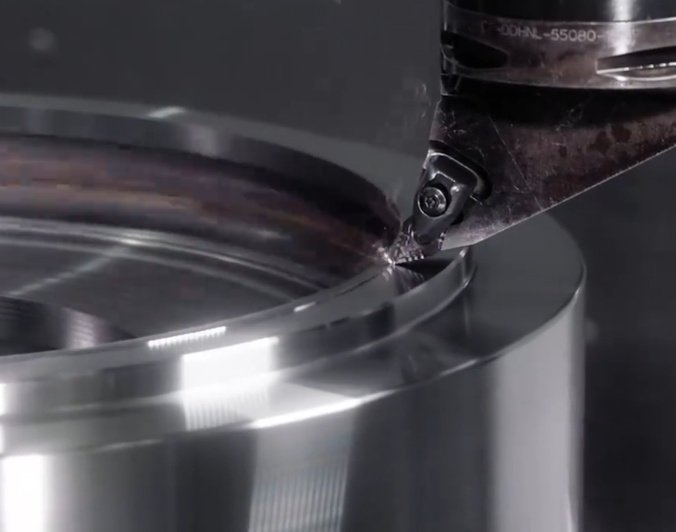
Spindle Design and Runout Control
The spindle is critical to dimensional accuracy and surface quality. Important spindle characteristics include:
- Low radial and axial runout (often ≤ 2–3 µm or better at the taper)
- High-precision bearings with appropriate preload
- Thermally stable design with controlled cooling
- Taper interface systems with repeatable tool seating (e.g., HSK, BT, CAT)
Spindle runout directly affects hole diameters, circularity, and surface finish. Ultra-precision applications may require sub-micrometer runout specifications.
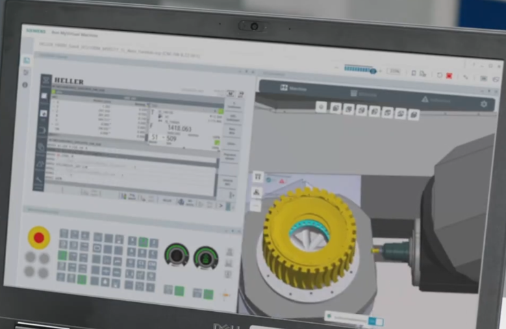
Control Systems, Feedback, and Compensation
Modern CNC control systems incorporate multiple feedback and compensation mechanisms to achieve and maintain high accuracy across the working envelope.
High-Resolution Encoders and Feedback Loops
Position feedback is obtained from encoders on the axes. The control system uses closed-loop servo control to match actual position to commanded position.
Key aspects:
- Scale or rotary encoders with fine resolution (e.g., 0.0001 mm or finer)
- Glass or magnetic linear scales mounted directly on the axes to measure actual table position
- High bandwidth servo loops to quickly correct deviations
Direct feedback from linear scales compensates for errors in ball screws, couplings, and thermal expansion of drive components.
Error Mapping and Volumetric Compensation
Every machine has inherent geometric errors: positioning error, straightness error, squareness error, and rotary axis misalignment. These can be measured and compensated.
Typical procedures include:
- Laser interferometer measurement of linear positioning error along each axis
- Ballbar measurement of circular interpolation error and contouring performance
- Volumetric error mapping using specialized instruments to capture multi-axis interaction errors
The results are stored in the CNC as error maps. During operation the control applies compensation to commanded positions, improving volumetric accuracy across the entire working volume.
Backlash and Pitch Error Compensation
Backlash and lead errors in ball screws can introduce positioning inaccuracies, especially when reversing direction. To mitigate these effects, high-precision CNC systems use:
- Mechanical preload and optimized ball screw design
- Electronic backlash compensation in the control
- Pitch error compensation tables along each axis
These methods help maintain consistent positioning performance under varying motion patterns.
Cutting Tool Selection and Tool-Related Accuracy Factors
Even with a highly accurate machine and control system, cutting tools and their management strongly influence the achievable tolerances and surface quality.
Tool Geometry, Material, and Coating
For tight tolerance machining, tool geometry and material must be matched to the workpiece material and required finish.
Important considerations:
- Tool material: carbide, cermet, CBN, PCD, HSS, or ceramics depending on hardness, abrasiveness, and thermal properties of the workpiece
- Geometry: rake angle, clearance angle, edge preparation, helix angle, corner radius or chamfer
- Coatings: TiAlN, TiCN, AlTiN, DLC, or other specialized coatings to reduce wear and heat
Stable tool geometry ensures consistent cutting forces, reducing dimensional drift during production runs.
Tool Holding, Runout, and Balance
The interface between the spindle and the cutting tool is another critical element. Improper tool holding can introduce runout, vibration, and deflection. Measures to minimize these effects include:
- High-precision tool holders (e.g., shrink-fit, hydraulic, high-precision collet chucks)
- Tool holder balancing to reduce vibration at high spindle speeds
- Minimized tool overhang to increase stiffness
Tool runout directly affects hole size, surface finish, and tool wear patterns, especially in drilling, reaming, and small-diameter end milling.
Tool Wear, Tool Life Management, and Compensation
Tool wear gradually changes tool dimensions and cutting behavior, which can lead to drift in part dimensions. In high-precision environments, tool wear is controlled by:
- Defined tool life limits based on time, cutting length, or number of parts
- In-process measurement to detect when dimensions start deviating
- Automatic tool offset compensation based on measured size trends
- Tool condition monitoring systems (e.g., spindle power, vibration, acoustic emission)
Tool length and diameter offsets are maintained accurately in the machine’s tool offset table. Changes in tool geometry are compensated by updating these offsets either manually or automatically.
Workholding, Fixturing, and Part Stability
How the workpiece is held and supported strongly influences the final dimensional accuracy and geometric integrity. Poor fixturing can negate the benefits of a highly accurate machine and program.
Fixture Rigidity and Repeatability
Precision fixturing aims to locate and support the workpiece in a defined, repeatable manner while resisting cutting forces. Typical principles include:
- Use of reference datums matched to design reference surfaces
- 3-2-1 locating principle (three points to define a plane, two for linear constraint, one for rotational constraint)
- Short, stiff clamping paths and direct support beneath cutting areas
- Use of hardened and ground locators, pins, and bushings
Repeatable fixture location minimizes variation between setups and allows reliable use of work offsets and coordinate transformation.
Clamping Forces, Distortion, and Deformation Control
Excessive or uneven clamping forces can distort the part, especially thin-walled or slender components. When the part is unclamped after machining, it may spring back, creating out-of-tolerance conditions.
To mitigate this, precision fixturing often includes:
- Uniform distribution of clamping forces
- Use of vacuum chucks or low-distortion clamping systems for thin parts
- Support under flexible areas to prevent deflection
- Optimized clamping sequence to avoid introducing stress
The machining process may also be split into roughing and finishing operations with different fixturing strategies to minimize residual stresses before finishing passes.
Workpiece Material Behavior and Stress Relief
Material properties and internal stresses influence dimensional stability. Key considerations include:
- Pre-machining stress relief heat treatments for castings, forgings, or welded structures
- Controlled removal of material to minimize uneven stress release
- Intermediate stress relief between roughing and finishing for critical parts
Stable material conditions help ensure that dimensions remain within tolerance not only during machining but also over the service life of the part.
Process Planning, Programming, and Path Generation
Accurate components result from detailed process planning and optimized CNC programming, not just from accurate machines. Careful selection of strategies helps control heat input, tool deflection, and geometric fidelity.
Operation Sequencing for Dimensional Stability
The order in which features are machined affects cumulative error and distortion. General principles for tight-tolerance machining include:
- Roughing operations first to remove the bulk of material and relieve stress
- Semi-finishing operations to bring features close to final size
- Finishing operations with light cuts, often using separate finishing tools
- Machining critical datum features early and referencing subsequent operations from them
- Splitting complex parts into multiple setups while maintaining consistent datums
Sequencing is particularly important for thin-walled parts, long shafts, and components with interacting geometric tolerances.
CAM Toolpaths and Tool Engagement Control
CAM (Computer-Aided Manufacturing) systems generate toolpaths that greatly influence cutting forces and temperature. For high accuracy, toolpaths are designed to maintain controlled tool engagement:
- Constant tool load strategies (e.g., trochoidal milling, adaptive clearing) for roughing
- Climb milling where feasible to reduce deflection and improve surface finish
- Optimized step-over and step-down values to limit radial and axial forces
- Smoothing of toolpaths to avoid sudden direction changes and jerks
Multi-axis toolpaths (3+2 or full 5-axis) are used when necessary to maintain a short tool length and to align the tool with complex features, improving both rigidity and access.
Cutter Compensation, Tool Offsets, and Program Accuracy
Dimensional control relies on accurate interpretation of the programmed toolpath relative to the actual cutting edges. Key mechanisms include:
- Cutter radius compensation (G41/G42) to account for actual cutter diameter
- Tool length compensation (G43/G44) for changes in tool length, especially after tool change
- Use of precise tool presetting equipment for initial tool offset measurement
When geometry changes are needed (for example, to correct a small diameter error), adjusting offsets rather than altering the CAD model ensures consistent dimensional corrections without modifying the nominal design.
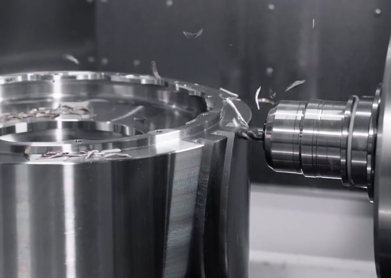
Cutting Conditions, Heat, and Vibration Control
Cutting parameters and dynamic behavior directly influence dimensional accuracy and surface integrity. Stable cutting processes minimize uncontrolled tool deflection and thermal distortion.
Feeds, Speeds, and Depths of Cut
Optimal cutting conditions balance high productivity with low forces and limited heat generation. For tight tolerances, finishing passes typically use:
- Reduced feed per tooth compared to roughing
- Shallow depth of cut and small radial engagement
- Moderate cutting speeds tuned to tool material and workpiece
Lower cutting forces during finishing minimize elastic deflection in the tool, workpiece, and machine structure, improving dimensional consistency.
Coolant Selection and Application
Coolant plays multiple roles: chip evacuation, lubrication, and temperature control. For precision machining, coolant systems are designed to:
- Maintain consistent coolant temperature to avoid thermal fluctuations
- Deliver coolant directly to the cutting zone, often through-tool coolant for deep holes
- Provide adequate flow to remove chips and prevent recutting
In some ultra-precision or finishing applications, minimum quantity lubrication (MQL) or even dry machining may be used when it leads to more predictable thermal behavior and less distortion.
Vibration, Chatter, and Dynamic Stability
Vibration and chatter adversely affect surface finish and dimensional accuracy. Dynamic stability is managed by:
- Selecting tool and holder combinations with favorable modal characteristics
- Adjusting spindle speed to avoid resonance frequencies
- Using variable pitch cutters to disrupt vibration patterns
- Employing damped tool holders for long overhangs
Stable cutting reduces random deviations and ensures repeatable feature dimensions over long production runs.
Environmental Control and Shop Conditions
Even with advanced machines and careful programming, the surrounding environment can introduce dimensional variation if not controlled appropriately.
Temperature and Humidity Management
Workpiece and machine dimensions change with temperature. To maintain tight tolerances, high-precision machining is commonly carried out in controlled rooms.
Typical measures include:
- Maintaining room temperature within ±1–2 °C, or better for very tight tolerances
- Avoiding drafts or direct airflow on machines or workpieces
- Allowing sufficient warm-up time for machines to reach thermal equilibrium
- Storing and inspecting critical parts in the same controlled environment
Humidity control helps protect sensitive materials and measuring instruments but generally plays a secondary role compared to temperature in dimensional stability.
Cleanliness, Chip Management, and Contamination Control
Chips, debris, and contamination can interfere with accurate machining and measurement. Good practices include:
- Regular cleaning of machine tables, fixtures, and workholding surfaces
- Effective chip conveyors and coolant filtration systems
- Preventing chips from being trapped between part and fixture locating surfaces
- Keeping metrology equipment in clean, controlled environments
Even small chips or debris under a workpiece can cause micrometer-level dimensional errors or angular misalignment.
Metrology, Inspection Strategies, and Feedback
Achieving tight tolerances requires not only producing accurate parts but also verifying them with suitable measurement methods. Metrology provides feedback for process adjustment and confirmation of compliance with specifications.
| Measurement Method | Typical Application | Typical Accuracy Range |
|---|---|---|
| Digital calipers | General dimensions, low to medium precision features | ±0.02 mm to ±0.03 mm |
| Micrometers | Shaft diameters, thickness, small external features | ±0.001 mm to ±0.003 mm |
| Dial bore gauges | Internal diameters and bore roundness | ±0.002 mm to ±0.005 mm |
| Height gauges + surface plate | Heights, steps, basic squareness and flatness | ±0.005 mm to ±0.01 mm |
| CMM (Coordinate Measuring Machine) | Complex 3D geometries, GD&T, profile, location | ±0.001 mm to ±0.005 mm (depending on machine and volume) |
| Optical comparators | Profiles, small features, 2D shapes | ±0.005 mm to ±0.01 mm |
| Surface roughness testers | Surface finish (Ra, Rz, etc.) | Depending on sensor and range |
| Laser scanners/optical 3D systems | Freeform surfaces, fast overall inspection | Typically micrometer to tens of micrometers |
In-Process Measurement and Probing
In many precision applications, measuring only after machining is insufficient. In-process measurement allows automatic correction before parts go out of tolerance.
Common techniques include:
- On-machine touch probes to locate part datums and measure critical features
- Tool setting probes to determine tool length and diameter directly in the machine
- Automatic offset adjustment based on probing results
Probing cycles can be integrated into CNC programs to measure features such as bores, pockets, or step heights, and then apply compensation to subsequent operations.
Offline Inspection and CMM Verification
For many critical components, final inspection is performed on high-accuracy coordinate measuring machines or other specialized equipment. Typical procedures include:
- Inspecting reference datums and primary dimensions
- Evaluating geometric tolerances: flatness, position, runout, etc.
- Generating full inspection reports for traceability and quality records
CMM measurement data can be analyzed statistically to identify trends, support process capability analysis, and guide corrective actions in machining.
Process Control, SPC, and Quality Assurance
High accuracy and tight tolerances must be maintained not only for individual parts but consistently across production batches. This requires structured process control and quality management practices.
Statistical Process Control (SPC) and Capability
SPC uses statistical methods to monitor key dimensions over time. Typical steps include:
- Selecting critical-to-quality (CTQ) dimensions based on function and tolerance sensitivity
- Regular measurement of these dimensions during production
- Plotting data on control charts (e.g., X-bar and R charts)
- Calculating process capability indices such as Cp and Cpk
High process capability indicates that the process reliably stays well within tolerance limits, reducing scrap and rework.
Gage R&R and Measurement System Analysis
Measurement systems themselves must be capable of resolving the required tolerances. Gage repeatability and reproducibility (Gage R&R) studies assess:
- Repeatability: variation when the same operator measures the same part multiple times
- Reproducibility: variation between different operators
- Overall measurement variation relative to part tolerance
As a general guideline, the measurement system variation should represent only a small fraction of the total tolerance to reliably distinguish acceptable from nonconforming parts.
Documentation, Traceability, and Process Standardization
Consistent high accuracy results from standardized, documented procedures. Typical elements include:
- Process plans and work instructions detailing setups, tools, and parameters
- Control of CNC program versions and change management
- Tool management systems with traceability of tool batches and usage
- Record keeping of inspection results, deviations, and corrective actions
Comprehensive documentation and traceability facilitate root-cause analysis when deviations occur and support compliance requirements in regulated industries.
Typical Accuracy Ranges in Precision CNC Machining
Actual achievable tolerances depend on part size, geometry, material, and production volume. The following ranges provide a general overview of what is commonly attainable under well-controlled conditions.
| Accuracy Level | Typical Tolerance Range | Example Applications |
|---|---|---|
| Standard machining | ±0.05 mm to ±0.1 mm | General mechanical parts, brackets, non-critical housings |
| Precision machining | ±0.01 mm to ±0.02 mm | Precision bushings, alignment features, moderate-fit components |
| High-precision machining | ±0.005 mm to ±0.01 mm | Hydraulic components, precision shafts, bearing seats |
| Ultra-precision machining | ≤ ±0.002 mm (≤ ±2 µm) | Optical components, high-end instrumentation, certain aerospace and semiconductor parts |
These ranges are indicative and assume properly maintained machines, optimized processes, and suitable environmental and inspection conditions. Actual capability must be verified for each specific application.
Common Practical Considerations and Issues
Implementing and maintaining tight-tolerance CNC machining often involves managing several recurring issues. Addressing these systematically improves both accuracy and productivity.
Thermal Drift Over Long Production Runs
As machines operate over several hours, temperatures gradually rise, leading to dimensional drift. Without compensation, parts produced later in the run may deviate from nominal dimensions.
Mitigation measures include:
- Machine warm-up routines before critical production
- Monitoring of key dimensions and periodic offset adjustment
- Use of thermal compensation functions when available
- Stabilizing coolant and ambient temperature
Balancing Productivity with Tolerance Requirements
Tighter tolerances often require lighter finishing cuts, finer tools, and more inspection, which can reduce throughput. Effective process planning aims to concentrate tight tolerances only where functionally necessary, avoiding over-specification of non-critical features.
Small Feature and Micro-Machining Challenges
Very small features or micro-machined components present specific difficulties:
- Extremely small tools are more prone to breakage and deflection
- Tool runout becomes a significant portion of feature size
- Measurement of micro-features requires specialized metrology
Managing these aspects demands strict control of toolholding, spindle condition, and inspection methods.
Conclusion
Precision CNC machining achieves tight tolerances and high accuracy through the combined effect of machine design, thermal stability, high-resolution controls, well-engineered cutting tools and fixtures, optimized process planning, controlled cutting conditions, and rigorous metrology and quality assurance.
Each element—from spindle runout and fixture rigidity to CAM toolpath strategy and CMM verification—contributes to the final dimensional result. When these factors are systematically designed, controlled, and monitored, CNC machining can reliably produce components with micrometer-level tolerances and complex geometric requirements, supporting the demands of advanced industries and critical applications.
