
CNC milling can deliver very high dimensional accuracy, but achievable tolerances depend on machine capability, process setup, material, tooling, and feature type. Understanding realistic tolerance levels is essential for economical, manufacturable designs and reliable parts.
Fundamental Concepts of CNC Milling Tolerances
Tolerance defines the permissible deviation from a nominal dimension. In CNC milling, tolerances are applied to linear dimensions, hole sizes, geometric relationships, and surface characteristics.
Types of tolerances in CNC milling
- Dimensional tolerances: linear sizes (length, width, thickness, diameter)
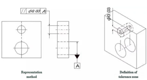
- Geometric tolerances (GD&T): form, orientation, location, and runout controls
- Surface-related tolerances: surface roughness and flatness of milled faces
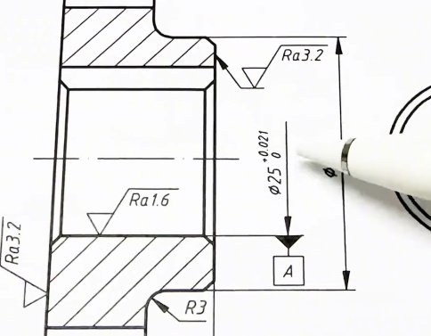
Dimensional tolerances are commonly expressed as unilateral or bilateral limits (e.g., 10.00 ±0.05 mm). Geometric tolerances use feature control frames in accordance with standards such as ASME Y14.5 or ISO 1101.
Typical CNC Milling Tolerance Ranges
Modern CNC mills can achieve different levels of accuracy depending on whether the operation is roughing, semi-finishing, or finishing. The following ranges are typical for well-maintained industrial equipment and controlled environments.
| Accuracy level | Typical linear tolerance (mm) | Typical linear tolerance (inch) | Typical applications |
|---|---|---|---|
| General machining | ±0.10 to ±0.20 | ±0.004 to ±0.008 | Brackets, housings, non-critical plates |
| Standard precision | ±0.05 to ±0.10 | ±0.002 to ±0.004 | Mechanical parts, fixtures, enclosures |
| High precision | ±0.01 to ±0.02 | ±0.0004 to ±0.0008 | Tooling, alignment features, precision jigs |
| Ultra-precision (selected features) | ±0.002 to ±0.005 | ±0.00008 to ±0.0002 | Mating bores, critical locators, precision optics mounts |
These ranges are indicative and assume appropriate tool paths, tooling, fixturing, and quality control. Achieving the tightest bands is usually limited to specific features, not the entire part.
Standard Tolerance Systems and Reference Grades
Many engineering drawings use standardized tolerance classes. These systems communicate general tolerances without specifying them on every dimension.
ISO 2768 general tolerances
ISO 2768 is widely used for machined parts. It defines general tolerances for linear and angular dimensions, and geometrical tolerances, where no specific tolerance is indicated.
- ISO 2768-m (medium): suitable for most general CNC-milled components
- ISO 2768-f (fine): used where higher precision is needed without detailed individual tolerances
Typical ISO 2768-m ranges for linear dimensions are approximately ±0.1 to ±0.3 mm for lengths up to 120 mm, widening with part size. ISO 2768-f is tighter, commonly around ±0.05 to ±0.15 mm in similar size ranges.
IT grades (International Tolerance grades)
IT grades (e.g., IT7, IT8, IT9) provide a systematic way to define hole and shaft fits. CNC milling commonly achieves IT8–IT10 for milled features and IT7–IT8 for precision bores combined with boring or reaming.
| IT grade | Approx. tolerance band at 10 mm (µm) | Typical machining method |
|---|---|---|
| IT7 | 16–25 | Finish boring, reaming, precision milling of selected features |
| IT8 | 25–40 | Fine milling, standard precision holes |
| IT9 | 40–64 | General milling for mating but non-critical parts |
| IT10 | 64–100 | General-purpose milling where fits are non-critical |
These values are indicative and depend on part size and process capability. For very tight fits, CNC milling is often combined with reaming, honing, or grinding.
Dimensional Tolerances for Common CNC-Milled Features
Different feature types have different practical tolerance limits due to tool deflection, cutting forces, access, and measurement methods.
Flat faces and plate thickness
For flat faces produced by end milling or face milling, typical achievable tolerances include:
- Thickness of small plates (<150 mm): ±0.02–0.05 mm
- Thickness of medium plates (150–500 mm): ±0.05–0.10 mm
- Local flatness: 0.02–0.05 mm over 100 mm, depending on setup and material
Better flatness and thickness control is possible with precision fixtures, stable materials, and fine finishing passes.
Holes, bores, and pockets
Holes and internal features are particularly sensitive to tool deflection, chip evacuation, and tool wear.
Typical CNC milling and drilling capabilities:
- Drilled hole diameter (standard twist drill): ±0.05–0.10 mm
- Milled circular pockets (end mill interpolation): ±0.01–0.03 mm on diameter for small to medium bores
- Precision bores with boring head: ±0.005–0.01 mm on diameter
For tighter fits, reaming or grinding may be applied after milling.
Slots, keyways, and narrow features
Slots and keyways are influenced by cutter diameter accuracy and deflection.
Typical tolerances:
- Slot width with standard end mills: ±0.02–0.05 mm
- Keyways milled with specialized cutters: ±0.01–0.03 mm on width
Long slender slots or high aspect ratio pockets are more prone to positional and dimensional drift and often require conservative cutting parameters and staged rough/finish passes.
Positional accuracy and hole patterns
CNC control enables accurate positioning, but thermal effects, backlash compensation, and part clamping influence results.
Typical achievable hole-to-hole positional tolerances:
- Within 0.02–0.05 mm for patterns up to ~200 mm
- Within 0.05–0.10 mm for patterns over several hundred millimetres
For critical dowel-pin patterns or alignment bores, additional probing, high-accuracy calibration, and controlled environments can reduce positional variation.
Geometric Tolerances in CNC Milling
Geometric Dimensioning and Tolerancing (GD&T) allows precise control of form, orientation, and location. CNC milling is suitable for many GD&T controls, provided the tolerances consider practical process capability.
Form tolerances
Form tolerances specify the shape of individual features regardless of their relationship with other features.
Typical form controls for milled parts:
- Flatness of machined faces: 0.01–0.05 mm, depending on area and process
- Straightness of edges: 0.01–0.03 mm over 100 mm
- Circularity of milled bores: 0.01–0.03 mm for moderate diameters
Achieving very tight form tolerances requires stable fixturing, low cutting forces, and careful temperature control.
Orientation tolerances
Orientation controls such as parallelism, perpendicularity, and angularity define how features relate to datums.
Indicative ranges:
- Perpendicularity between milled faces: 0.02–0.05 mm over 100 mm
- Parallelism of opposite faces: 0.01–0.03 mm over 100 mm
- Angular features: 0.1–0.2 degrees for general features, finer with precision setups
Multi-axis machines and precise probing can improve orientation consistency, especially when fewer re-clampings are required.
Location and runout tolerances
Location and runout controls set the positional and rotational accuracy of features relative to datums.
Typical practical limits:
- True position of holes on a plane: 0.02–0.10 mm depending on pattern size
- Total runout of rotating features machined in one setup: 0.01–0.03 mm
Where very low runout is required (e.g., spindle interfaces), grinding or superfinishing steps may follow the milling operations.
Surface Finish Tolerances in CNC Milling
Surface roughness affects sealing, friction, fatigue performance, and aesthetics. CNC milling can deliver a range of surface finishes depending on tool type, feed, speed, and finishing strategy.
Typical surface roughness ranges
For common CNC milling operations, typical surface roughness values (Ra) are:
- Roughing: 3.2–6.3 µm Ra
- General finishing: 1.6–3.2 µm Ra
- Fine finishing (small step-over, sharp tools): 0.4–1.6 µm Ra
End-milled surfaces often have visible tool marks. Face milling with high-quality inserts and optimized passes can achieve lower Ra values. Superfinishing requirements below 0.2 µm Ra usually need grinding, polishing, or lapping after milling.
Surface finish vs tolerance relationship
Surface roughness interacts with dimensional tolerances. Very tight tolerances on small features can be undermined by coarse surface finish because peak-to-valley height becomes a significant fraction of the tolerance band. Specifying both tight dimensional tolerance and low Ra is essential when the effective size is influenced by surface texture.
Factors Influencing Achievable CNC Milling Tolerances
Even highly capable machinery cannot reach tight tolerances if process factors are not controlled. Understanding key influences helps set realistic expectations and optimize designs.
Machine tool capability
Machine construction, spindle accuracy, and axis control are fundamental. Relevant characteristics include:
- Positioning accuracy and repeatability of linear axes
- Spindle runout and stiffness
- Thermal stability of the machine structure
High-end machining centres typically offer sub-0.005 mm repeatability, enabling high precision on suitable features. Older or lighter machines may be limited to wider tolerance bands.
Tooling, tool wear, and tool holding
Cutting tools and holders directly affect dimensional accuracy:
- Tool deflection causes undersize/oversize and shape distortion
- Tool wear gradually shifts feature sizes and surface finish
- Runout in tool holders impacts hole diameters and circularity
Using rigid, balanced tool holders and controlling tool life through preset tool offsets and wear compensation is essential for consistent tolerances.
Material properties and workpiece behaviour
Material affects cutting forces, heat generation, and elastic recovery:
- Aluminium alloys: allow tighter tolerances due to lower cutting forces and good machinability
- Steels: typically require more conservative tolerances, especially hardened grades
- Stainless steels and nickel alloys: higher heat and work hardening can reduce achievable tolerance consistency
- Plastics: prone to thermal expansion, elastic deformation, and residual stress, often requiring wider tolerances or special approaches
Residual stresses in materials can cause distortion during and after machining, affecting flatness and straightness tolerances.
Fixturing and workholding
Workholding must provide rigidity without distorting the part:
- Insufficient clamping rigidity leads to vibration and dimensional scatter
- Excessive clamping forces can deform thin-walled parts, relaxing after release
- Repositioning between setups introduces additional alignment error
Dedicated fixtures, vacuum fixtures for thin plates, and well-planned datum schemes reduce these effects and support tighter tolerances.
Thermal effects and environment
Temperature changes cause both machine and workpiece to expand or contract. For high precision:
- Machine and workpiece should reach thermal equilibrium before fine finishing
- Shop ambient temperature should be relatively stable
- Coolant use and cutting strategies should avoid large localized temperature gradients
For precision components, measurements are often referenced to 20 °C. When parts will operate at different temperatures, thermal expansion must be accounted for in the tolerance analysis.
Programming strategy and process planning
CAM strategies and process planning strongly influence precision:
- Separate roughing and finishing passes allow removal of most material before the final precision cut
- Consistent climb milling or conventional milling strategy can be used based on machine behaviour
- Control of tool engagement and step-over reduces deflection and improves surface finish
For tight tolerances, finishing passes usually remove a small, consistent allowance (e.g., 0.1–0.3 mm) and use stable cutting parameters, with fresh tools where needed.
Measurement and inspection capability
Tight tolerances must be verifiable. Inspection capability includes:
- Calipers and micrometers for general tolerances (±0.01–0.02 mm range)
- Height gauges and bore gauges for more precise dimensions
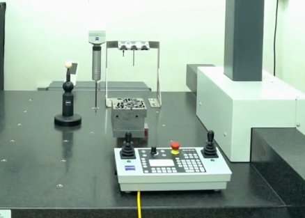
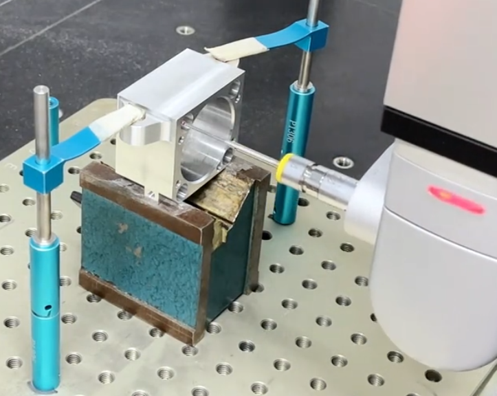
- Coordinate Measuring Machines (CMM) for complex GD&T requirements
- Surface roughness testers for Ra and other surface parameters
If inspection equipment is less accurate than the specified tolerance, verification becomes unreliable. A common practice is that measurement system uncertainty should be significantly smaller than the tolerance band.
Practical Tolerance Guidelines by Application
Application requirements strongly influence which tolerances are appropriate. Over-specifying tolerances increases cost, while under-specifying can cause assembly or performance issues.
General mechanical components
For structural brackets, non-critical housings, and covers:
- Linear dimensions: ±0.10–0.20 mm
- Hole diameters for clearance: ±0.10 mm
- Positional tolerances: 0.10–0.20 mm for bolt patterns
For these parts, general tolerances such as ISO 2768-m are often adequate.
Precision mechanical assemblies
For components that must align or move relative to each other, such as linear guides, precision fixtures, and gear housings:
- Key locating faces: ±0.01–0.03 mm
- Hole/bore diameters for dowel pins: ±0.005–0.01 mm (often with reaming)
- Positional tolerances for mating holes: 0.02–0.05 mm
- Flatness and perpendicularity: 0.01–0.03 mm over 100 mm where critical
CNC milling, combined with specific finishing operations where needed, is well suited to these requirements.
High-precision and metrology components
For optical mounts, metrology fixtures, and fine mechanical systems, very tight tolerances may be needed on a limited number of features:
- Selected precision bores: ±0.002–0.005 mm (with boring/reaming and careful process control)
- Critical datums: flatness and straightness within 0.005–0.01 mm over moderate lengths
- Positional tolerances in hole patterns: 0.01–0.02 mm with optimized setup and environment
In many of these cases, CNC milling is part of a process chain including grinding, honing, or lapping for final refinement.
Design Considerations and Tolerance Specification Strategy
Specifying tolerances thoughtfully is central to balancing performance, manufacturability, and cost.
Use tight tolerances only where function requires them
Overly tight tolerances across an entire drawing can lead to unnecessary rework and rejection. Tighter controls should be limited to:
- Mating features affecting fit, alignment, or movement
- Features critical to safety or performance
- Datum surfaces used to locate or reference other parts
Non-critical areas can often use general tolerances from ISO 2768 or similar standards.
Specify functional GD&T instead of tightening all dimensions
Rather than uniformly reducing all dimensional tolerances, GD&T allows explicit control of how parts must function. For example, using positional tolerances relative to functionally chosen datums often gives more predictable assembly behaviour than extremely tight size tolerances alone.
Coordinate tolerances with manufacturing capability
Tolerance specification should consider the likely manufacturing processes:
- Confirm whether the supplier’s CNC milling capability aligns with the tolerance requirements
- Discuss whether secondary operations (such as reaming or grinding) are needed and feasible
- Ensure inspection methods are available for any geometric and surface requirements
Design-for-manufacturing reviews and capability studies can validate that tolerances are attainable and sustainable in production.
Consider feature size, aspect ratio, and accessibility
Slender, deep, or poorly accessible features are harder to control. For example:
- Deep pockets with high depth-to-width ratios are more prone to deflection
- Thin walls can deform from cutting forces and clamping
- Small radius internal corners are limited by tool diameter and deflection
Relaxing tolerances or adjusting geometry (e.g., thicker walls, larger corner radii) can significantly improve manufacturability while preserving functional requirements.
Common Issues Related to CNC Milling Tolerances
When tolerances are not aligned with process realities, several recurring issues occur in practice.
Assembly interference or loose fits
If mating parts are cut at the extremes of tolerance ranges, assemblies may be too tight or too loose. Using fit systems (such as hole-basis fits with IT grades) and appropriate GD&T position controls reduces these risks.
Dimensional drift during longer production runs
Tool wear, thermal drift, and minor setup changes can gradually shift actual dimensions. Without tool wear compensation or statistical process control, parts may drift toward tolerance limits over time.
High rejection rates due to inconsistent tolerances
Parts with numerous extremely tight tolerances often show higher scrap and rework rates. This increases cost and lead time. Rationalizing tolerances to what is functionally required, and grouping tight tolerances around critical areas, mitigates this problem.
Difficult measurement and verification
Very small tolerances with complex GD&T callouts require specialized inspection equipment and expertise. If such capabilities are not available, verification becomes unreliable or excessively time-consuming, delaying delivery and creating uncertainty about actual quality.
Summary of Realistic CNC Milling Precision Levels
In practical terms, CNC milling can consistently achieve the following ranges when process conditions are well managed:
- General-purpose parts: ±0.10–0.20 mm on most linear dimensions
- Precision parts: ±0.01–0.05 mm on critical dimensions and 0.02–0.05 mm positional tolerances
- High-precision features: ±0.002–0.01 mm on selected bores and datums, often with supplementary operations and controlled environments
Using appropriate standards (such as ISO 2768 and IT grades), functional GD&T, and sound process control, CNC milling provides reliable and repeatable tolerances suitable for a wide range of industrial applications.
