
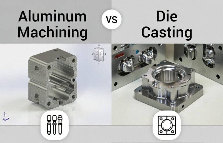
Aluminum components are widely used in automotive, aerospace, electronics, machinery, medical devices and consumer products. Among the most common industrial methods to manufacture aluminum parts are CNC machining and high-pressure die casting. Understanding their technical characteristics, cost structure and application suitability is essential for choosing the best process for a given part.
Fundamental Process Overview
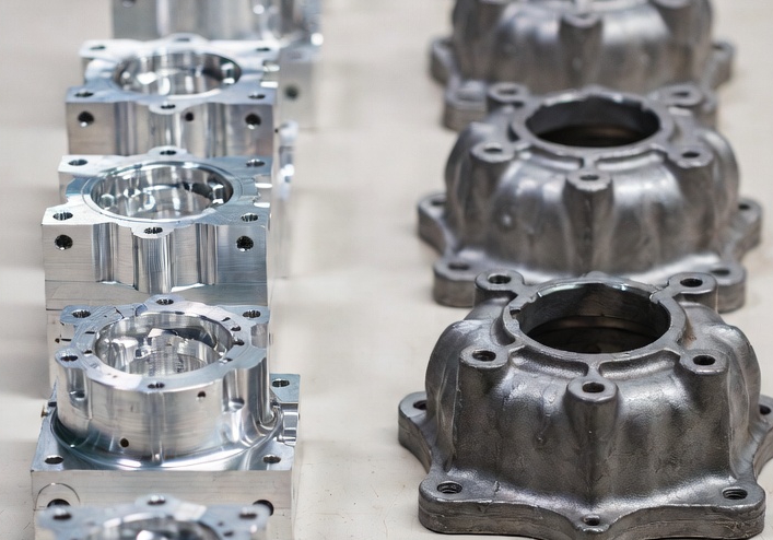
Aluminum machining and die casting represent two fundamentally different approaches to creating parts. Machining is a subtractive process, while die casting is a near-net-shape forming process using molten metal.
Aluminum Machining Basics
aluminum machining typically refers to CNC milling, turning, drilling and related metal-cutting operations performed on wrought aluminum stock (bar, plate, extrusion, forging, or preform). Material is removed by cutting tools to achieve the required geometry.
- Process type: Subtractive manufacturing
- Typical equipment: 3–5 axis CNC mills, CNC lathes, mill-turn centers, machining centers
- Material input: Solid stock (round bar, plate, blocks, extrusions, forged blanks)
- Preferred for: Low-to-medium volumes, high precision, complex features, iterative development
Machining allows flexible modification of geometry via CAM programming and toolpath adjustments. It generally requires limited dedicated tooling beyond fixtures and cutting tools, which are reusable across many part numbers.
Aluminum Die Casting Basics
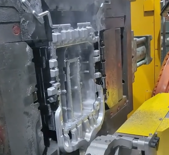
Aluminum die casting is a high-pressure casting process where molten aluminum is injected into a steel mold (die), where it solidifies to form near-net-shape parts.
- Process type: Near-net-shape forming
- Typical equipment: Hot-chamber or cold-chamber die casting machines (for aluminum, cold-chamber is prevalent)
- Material input: Aluminum casting alloys, ingots or recycled feedstock
- Preferred for: High volumes, repeated production of identical parts, complex external shapes
The core of die casting is a multi-part steel die with cavities and cores defining the part geometry. Shots are repeated at high speed, and the same die can produce hundreds of thousands of parts when properly designed and maintained.
Process Steps and Workflow
Both methods follow a structured workflow from design to finished parts, but the phase distribution of time and cost differs significantly.
Workflow for Aluminum Machining
Typical process steps include:
- Design of the part and creation of 3D model
- Selection of material form (plate, bar, extrusion, forging)
- Fixture and workholding design
- CAM programming and toolpath generation
- Setup of CNC machine (tooling, fixtures, work offsets)
- Machining operations (roughing, semi-finishing, finishing)
- Deburring, edge breaking, possible heat treatment
- Secondary operations (tapping, reaming, honing if needed)
- Surface finishing (anodizing, painting, plating, bead blasting where required)
- Inspection and quality verification
Lead time for machining is often dominated by programming, setup and material procurement, rather than hardware or tooling fabrication.
Workflow for Aluminum Die Casting
Typical process steps include:
- Design of the cast part with casting-specific features (draft, fillets, gating)
- Design and engineering of the die (cavity layout, runners, overflows, cooling channels, ejector system)
- Die manufacturing (steel selection, machining, EDM, assembly, tryout)
- Setup of die casting machine (press selection, shot sleeve, ladle or dosing system, die mounting)
- Melting and alloy management
- Trial shots and process parameter optimization (temperature, shot speed, pressure)
- Series production (injection, solidification, ejection, trimming)
- Secondary operations (deburring, machining of critical features where required)
- Surface finishing and coating if needed
- Final inspection and dimensional control
For die casting, the initial die design and manufacture constitute a significant portion of lead time and cost. Once the die is ready, per-part cycle times can be very short.

Material Considerations and Alloy Selection
Aluminum alloys used for machining and die casting differ in composition, mechanical behavior and response to processing.
Alloys for Machining
Machined parts are commonly produced from wrought alloys. Examples include:
- 2xxx series (e.g., 2024): High strength, used in aerospace structures
- 6xxx series (e.g., 6061, 6082): Good machinability, weldability, widely used for general engineering
- 7xxx series (e.g., 7075): Very high strength, used in aerospace and high-performance components
Wrought alloys usually have finer grain structure, lower porosity and higher mechanical properties than cast alloys. They are available in various temper conditions (e.g., T6, T651) tailored to strength, toughness and dimensional stability.
Alloys for Die Casting
Die casting uses alloys optimized for fluidity, hot cracking resistance and minimal die soldering rather than maximum strength. Common families include:
- Al-Si (e.g., AlSi9Cu3, AlSi10Mg): Good castability, used widely in automotive components
- Al-Si-Cu and Al-Si-Mg variants: Balance of castability, strength and ductility
These alloys solidify under high cooling rates within the die. Microstructure includes dendritic aluminum and eutectic silicon phases, sometimes modified and refined. Mechanical properties are influenced by cooling rate, porosity, defect control and any subsequent heat treatment.
Dimensional Accuracy and Tolerances
Dimensional accuracy is one of the main differentiators between machining and die casting. Machining can typically achieve finer tolerances directly in the process, while die casting often requires secondary machining for critical features.
| Feature / Condition | Aluminum Machining (CNC) | Aluminum Die Casting (as-cast) |
|---|---|---|
| General linear dimensions (up to ~100 mm) | ±0.01–0.05 mm (depending on setup and equipment) | ±0.1–0.3 mm (depending on die size and process control) |
| General linear dimensions (~100–300 mm) | ±0.02–0.1 mm | ±0.2–0.5 mm |
| Tight precision features (bores, critical fits) | Down to ±0.005 mm with proper tooling | Typically require post-machining for tight fits |
| Flatness (small surfaces) | < 0.02 mm achievable | Usually > 0.05–0.1 mm, may need machining |
| Repeatability in series | High, dependent on fixturing and thermal stability | High within die life, but influenced by wear and temperature |
The actual tolerances depend on machine capability, fixturing, part geometry, measurement environment (temperature) and inspection standards (e.g., ISO 2768, ISO 8062, company-specific standards).
Surface Finish and Geometric Characteristics
Aluminum machining and die casting yield different surface texture and geometric attributes.
Surface Roughness
Typical Ra (arithmetical mean roughness) ranges:
- CNC machining (roughing): Ra ≈ 3.2–6.3 µm
- CNC machining (finishing, standard): Ra ≈ 0.8–1.6 µm
- CNC machining (fine finishing or high-speed machining): Ra ≈ 0.2–0.8 µm
- Die casting (as-cast surfaces): Ra ≈ 1.6–6.3 µm depending on die condition
Machining tends to produce directional tool marks. Die-cast surfaces generally appear more uniform but can show flow lines, gate vestiges and slight texture from the die cavity finish.
Geometric Features
Die casting can create complex external geometry including ribs, bosses, thin walls and integrated mounting features in one shot. However, internal undercuts typically require cores, slides or special mechanisms in the die. Machining can reach complex internal features using multi-axis capability, but some deep internal cavities may be inaccessible or uneconomical.
Machined parts do not require draft angles for tool removal, whereas die-cast parts must include draft on all surfaces perpendicular to the die opening direction to facilitate ejection and reduce wear.
Mechanical Properties and Structural Integrity
Mechanical performance is strongly influenced by microstructure, porosity and residual stress. These differ substantially between machined and die-cast aluminum parts.
Properties of Machined Aluminum Parts
Machined parts inherit properties of the starting wrought material. Typical characteristics include:
- Higher tensile and yield strength compared to cast alloys for similar alloy systems
- Lower porosity, leading to better fatigue performance and more predictable mechanical behavior
- Directional properties depending on rolling or extrusion direction of the starting stock
Residual stresses can be present if the stock was quenched or unevenly cooled (e.g., thick plates). Stress-relieved tempers and proper machining strategies help control distortion.
Properties of Die-Cast Aluminum Parts
Die-cast parts typically exhibit:
- Moderate tensile and yield strength, lower than high-strength wrought alloys but sufficient for many applications
- Presence of micro-porosity or gas porosity; vacuum assist and process optimization can reduce but not always eliminate it
- Rapid cooling leading to refined microstructure near the surface and coarser structure in thicker sections
For components requiring pressure tightness, such as hydraulic or pneumatic housings, porosity control and potential impregnation treatments may be required when using die casting.
Design Rules and Constraints
Designing for machining and die casting requires adherence to different geometric rules and constraints to ensure manufacturability, quality and cost control.
Design Considerations for Machining
Important aspects include:
- Tool access: Features must be reachable by cutting tools, considering tool length, collision avoidance and machine axes
- Feature orientation: Aligning critical features with primary setups reduces re-clamping and improves accuracy
- Minimum wall thickness: Very thin walls may deflect and vibrate, degrading surface finish and tolerances
- Corner radii: Internal corners require finite radii dictated by tool diameter; sharp internal corners cannot be produced with rotary tools
- Workholding: Adequate clamping surfaces and reference features are necessary for repeatable positioning
Machining allows design flexibility with respect to undercuts and complex shapes when using multi-axis equipment, but time and cost increase with complexity.
Design Considerations for Die Casting
Key design rules for die casting include:
- Draft angles: Typically 1–3° per side on walls to aid ejection and reduce die wear
- Uniform wall thickness: Helps minimize hot spots, shrinkage porosity and distortion
- Ribs and bosses: Used for stiffness and local reinforcement; must be proportioned to avoid thick sections
- Fillets and radii: Sharp corners are avoided to improve flow, reduce stress concentration and extend die life
- Gating and overflow locations: Must support complete filling and air evacuation
- Core and slide design: Internal undercuts require cores or slides, increasing die complexity and cost
These design constraints are often formalized in company-specific design guidelines for die-cast parts.
Cost Structure and Production Volume Considerations
Total cost is determined by fixed and variable components. The balance between high initial investment and low per-part cost is a central difference between machining and die casting.
| Aspect | Aluminum Machining | Aluminum Die Casting |
|---|---|---|
| Tooling investment | Low to moderate (fixtures, general tooling) | High (dedicated steel dies, slides, ejector systems) |
| Per-part material usage | Higher (chips are generated and must be recycled) | More efficient, near-net shape, less scrap per part |
| Cycle time per part | Minutes to hours, depending on part complexity | Seconds to a few minutes per shot |
| Economic volume range | Low to medium volumes, prototypes, small series | Medium to very high volumes, mass production |
| Changeover flexibility | High, with reprogramming and setup changes | Limited once die is built; design changes require die modification |
For low volumes and frequent design changes, machining often yields lower total cost because it avoids the high initial expenditure on dies. For large, stable production volumes, die casting generally provides lower cost per part after amortization of the die.
Lead Time and Responsiveness
Lead time and ability to respond to design changes differ significantly between the two processes.
Lead Time for Machining
Lead time for machined aluminum components is often driven by material availability, programming and shop capacity. The absence of dedicated dies means initial parts can be produced relatively quickly after design completion. Design modifications can be implemented by updating the CAD model and CAM programs, usually without hardware changes other than possible fixture adjustments.
Lead Time for Die Casting
Die casting requires substantial time for die design, die manufacturing, machine setup and process tuning. The overall lead time is longer, especially for complex dies with multiple cavities and slides. Once the die is commissioned, however, the process can deliver parts at high rate. Design changes that affect cast geometry may require partial or complete die modification, adding cost and time.
Typical Applications and Use Cases
The selection between machining and die casting is closely linked to application requirements such as mechanical performance, weight, dimensional accuracy and expected production volume.
Common Applications for Machined Aluminum Parts
Machined aluminum is widely used in:
- Aerospace structural components, brackets, fittings and housings requiring high strength and low weight
- Precision mechanical assemblies, measuring equipment and high-accuracy fixtures
- Medical devices and instrumentation with tight tolerances and complex internal features
- Low-volume automotive and motorsport parts, prototype and racing components
- Industrial equipment parts where design changes are frequent or load conditions are severe
Machining is frequently chosen when design maturity is low, qualification cycles are ongoing, or when direct control over mechanical properties and inspection is critical.
Common Applications for Die-Cast Aluminum Parts
Die-cast aluminum is common in:
- Automotive housings, transmission cases, engine covers, brackets and structural castings
- Consumer electronics enclosures, heat sinks and structural frames
- Appliance components, motor housings and gearboxes
- Lighting housings, architectural hardware and mass-produced mechanical parts
These applications benefit from repeatable high-volume output, integrated features and the ability to consolidate multiple components into a single casting.
Secondary Operations and Finishing
Both approaches often require additional operations to reach final specification, especially for threads, precision bores and surface treatments.
Secondary Operations After Machining
Typical operations include:
- Deburring and edge breaking to remove sharp edges and burrs
- Thread forming or tapping for internal and external threads
- Reaming and honing for high-precision bores
- Anodizing, hard anodizing, painting or plating for corrosion resistance and appearance
Machined surfaces are usually ready for finishing without additional shaping, although polishing or bead blasting can be used to adjust surface texture.
Secondary Operations After Die Casting
Die-cast parts commonly undergo:
- Gate and runner removal, trimming of flash and excess material
- Shot blasting or tumbling to improve surface uniformity
- Machining of critical surfaces, bores, sealing faces or threads
- Surface finishing such as painting, powder coating, plating or anodizing (depending on alloy)
Critical load-bearing interfaces, sealing surfaces and functional holes are often machined after casting to ensure required tolerances and surface quality.
Quality Control and Inspection
Quality assurance approaches are similar in principle but emphasize different defect types for the two processes.
Inspection of Machined Aluminum Parts
Typical quality control methods include:
- Dimensional inspection with calipers, micrometers, gauges and coordinate measuring machines (CMM)
- Surface roughness measurement using profilometers where required
- Flatness and straightness checks with granite plates and dial indicators
- Residual stress assessment and distortion monitoring when high accuracy is needed
Defects to monitor include tool marks, chatter, out-of-tolerance dimensions, burrs, and surface damage.
Inspection of Die-Cast Aluminum Parts
Quality control is focused on:
- Dimensional checks against casting-specific tolerance standards
- Non-destructive testing to detect porosity, shrinkage and internal defects (X-ray inspection, CT scanning, dye penetrant for surface-breaking flaws)
- Leak testing for pressure-tight components
- Mechanical testing of coupons or sample parts for tensile and impact properties
Defects of interest include cold shuts, misruns, porosity, hot tears, incomplete filling, and die-related issues such as mismatch or flash.
Environmental and Material Utilization Aspects
Both machining and die casting can be integrated into aluminum recycling loops, but material utilization and energy distribution differ.
Material Utilization
Machining creates chips and offcuts that need collection and recycling. Efficient chip management, segregation of alloys and contamination control are important for reclaiming material value. In die casting, runners, sprues and reject castings can be remelted and reused in the casting furnace, improving overall material utilization at the foundry level.
Process Energy Considerations
Machining energy is primarily spent on spindle power, axis drives and ancillary systems. Die casting consumes energy to melt and hold aluminum at temperature, as well as for hydraulic and mechanical systems in the casting machine. The energy per part depends heavily on batch size, part mass and process efficiency.
Selection Guidelines: When to Use Machining vs Die Casting
Choosing between aluminum machining and die casting requires balancing technical requirements, volume expectations and economic factors. The following guidelines summarize typical selection criteria.
Situations Favoring Aluminum Machining
- Low or uncertain production volumes
- High requirement for dimensional accuracy and tight tolerances over many features
- High mechanical performance and fatigue resistance requirements, often using wrought high-strength alloys
- Frequent design changes or ongoing development iterations
- Need for complex internal geometry without the constraints of draft angles and die parting lines
Situations Favoring Aluminum Die Casting
- High and stable production volumes with consistent demand
- Parts with complex external shapes, integrated ribs, bosses and mounting features
- Need for near-net shape production to minimize post-processing and material waste
- Cost sensitivity for per-piece price once tooling is amortized
- Applications where as-cast mechanical properties meet or exceed requirements
Common Issues and Considerations
In practical engineering and manufacturing, certain recurring issues often influence the decision between machining and die casting.
Machining-Related Considerations
- Cycle time and machine utilization: Complex parts with numerous operations can occupy machines for extended periods.
- Tool wear and selection: Aluminum’s tendency to adhere to cutting edges demands proper tool coatings, geometries and cutting fluids.
- Distortion: Removal of large amounts of material from stress-bearing stock can result in dimensional changes.
Die-Casting-Related Considerations
- Porosity and leak tightness: Pressure-containing components may require enhanced process control or part impregnation.
- Die wear: High-pressure cycles and thermal fatigue progressively change die dimensions and surface, affecting part quality.
- Design restrictions: Drafts, uniform wall thickness and gating constraints can limit design freedom compared to machining.
Integrated Approaches and Hybrid Strategies
In many cases, the best solution does not rely exclusively on machining or die casting. Instead, a hybrid approach is implemented:
- Die casting to produce a near-net shape blank, followed by precision machining of critical surfaces and features.
- Use of standard die-cast housings combined with machined inserts or subcomponents for high-precision interfaces.
Such combinations can leverage the cost efficiency of die casting for bulk material and geometry, while retaining the precision and flexibility of machining where required.
Conclusion
Aluminum machining and die casting each occupy essential roles in modern manufacturing. Machining offers high accuracy, flexibility and strong mechanical properties from wrought alloys, making it suited for low-volume, high-performance and development-intensive applications. Die casting delivers high-volume, near-net-shape production with integrated features, enabling cost-effective mass manufacture once tooling is in place.
A systematic evaluation of design requirements, performance targets, expected volumes, tolerance needs, and economic constraints allows engineers to determine whether machining, die casting or a hybrid approach is the most appropriate solution for a given component.
