
Custom CNC machining is a widely used method for producing rapid prototype parts with accurate dimensions, repeatable quality, and production-grade materials. It bridges the gap between concept and production by offering fast turnaround, flexibility in design, and compatibility with a broad range of metals and plastics.
What Is Custom CNC Machining for Rapid Prototypes
Custom CNC machining for rapid prototyping refers to the use of computer numerical control (CNC) equipment to manufacture unique or low-volume parts directly from CAD data. Unlike mass production, each prototype or small batch can be tailored in geometry, material, and finishing without dedicated tooling.
In a typical workflow, engineers create a 3D CAD model and export it as a neutral file (such as STEP or IGES). CAM software converts this geometry into toolpaths, which guide CNC machines to remove material from solid stock. This subtractive approach is suited to parts that require tight tolerances, functional testing, or specific mechanical properties.
Custom CNC machining is compatible with iterative design cycles, allowing engineers to adjust dimensions, features, and materials between prototype builds. It supports functional prototypes, pre-production samples, and low-volume end-use parts.
Key Advantages for Rapid Prototype Parts
Custom CNC machining offers several benefits that are particularly relevant to rapid prototyping and early-stage product development.
- High dimensional accuracy and repeatability for functional testing
- Compatibility with many engineering metals and plastics
- Fast turnaround once CAD data and machining setups are ready
- Ability to produce complex 3D geometries with milled and turned features
- Direct use of production-grade materials for realistic performance evaluation
Dimensional accuracy is critical when prototypes interface with existing components such as bearings, shafts, or fasteners. CNC machining can maintain tight tolerances on critical dimensions, allowing prototypes to simulate final products reliably.
Using the same or similar materials as the intended production parts enables meaningful testing of mechanical strength, stiffness, thermal behavior, wear resistance, and other functional characteristics.
Core CNC Processes Used for Prototyping
Rapid prototyping with CNC primarily uses two fundamental processes: CNC milling and CNC turning. These can be combined, along with auxiliary operations, to produce complex parts.
CNC Milling
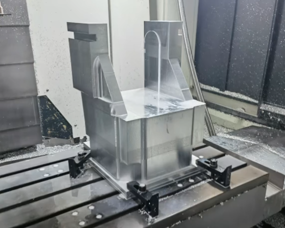
CNC milling employs rotating cutting tools to remove material from stationary workpieces. It is suitable for prismatic components, complex 3D surfaces, pockets, slots, and detailed features.
Common milling capabilities for prototype parts include:
- 2-axis and 3-axis milling for common geometries and flat features
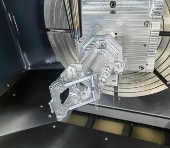
- 3+2 and full 5-axis milling for undercuts, impellers, and complex surfaces
- High-speed machining for aluminum and plastics to reduce cycle time
- Micro-milling for small features and fine details
Milling can generate parts from small brackets and enclosures to housing components, manifolds, and test fixtures. For rapid prototyping, 3-axis milling covers most requirements, while 5-axis machining becomes relevant for parts that would otherwise need multiple fixturing setups.
CNC Turning
CNC turning uses a rotating workpiece and stationary or moving cutting tools to produce parts with rotational symmetry, such as shafts, bushings, and threaded components. For rapid prototype parts, turning is often combined with milling to add flats, holes, and slots.
Typical turning capabilities include:
– Straight and stepped diameters
– Internal and external threading
– Boring and grooving operations
– Live-tooling or mill-turn operations for secondary features
Turned prototypes are common in automotive, industrial, and fluid power systems where cylindrical geometries and precise fits are required.
Additional Operations and Secondary Processes
Depending on functional requirements, prototype parts may require additional processes beyond milling and turning:
– Drilling and tapping for threaded holes
– Reaming for precise holes with tight tolerances
– Broaching or slotting for keyways and internal profiles
– Basic deburring and edge breaking for safe handling and assembly
These operations are often incorporated into the same CNC program where possible to reduce handling and maintain alignment between features.
Materials for CNC-Machined Prototype Parts
Material selection is central to prototype performance and test validity. CNC machining supports a wide range of materials that approximate or match production-grade options. The table below summarizes common materials used for rapid prototype parts manufactured by CNC machining.
| Material Category | Typical Grades | Key Characteristics | Typical Uses in Prototypes |
|---|---|---|---|
| Aluminum | 6061-T6, 7075-T6, 2024-T3, 6082 | Lightweight, good machinability, good strength-to-weight ratio, corrosion resistance | Housings, brackets, structural frames, heat sinks, aircraft and automotive components |
| Steel | 1018, 1045, 4140, 4340, tool steels (D2, O1) | High strength, stiffness, wear resistance, can be heat treated for hardness | Drive components, fixtures, gears, tooling prototypes, structural test parts |
| Stainless Steel | 304, 316, 17-4 PH | Corrosion resistance, good strength, suitable for harsh environments | Medical devices, food-processing components, marine hardware prototypes |
| Brass & Copper Alloys | C360 brass, C110 copper, bronze | Excellent machinability (brass), thermal and electrical conductivity (copper) | Electrical connectors, thermal components, fluid fittings, decorative prototypes |
| Plastics | ABS, POM (Delrin), PEEK, Nylon, PC, PMMA | Lightweight, electrical insulation, chemical resistance, varied mechanical properties | Enclosures, insulators, wear components, medical and lab equipment parts |
| Composites and Others | G10/FR4, carbon-fiber plates | High stiffness-to-weight ratio, dimensional stability, specific electrical properties | Structural panels, electronic substrates, specialized lightweight parts |
When selecting materials for prototypes, engineers often balance machining cost, lead time, and functional similarity to production materials. For example, aluminum may be chosen for early prototypes even if the final part will be die-cast zinc, as long as mechanical and thermal behavior remain sufficiently representative.
Design Guidelines for CNC Prototype Parts
Designing with CNC machining in mind can reduce lead times, machining costs, and the risk of dimensional issues. While each project is unique, several general guidelines apply to most prototype parts.
Geometry and Feature Design
– Avoid excessively thin walls that may vibrate or deflect under cutting forces. As a typical baseline, wall thickness of 0.8–1.0 mm for metals and 1.5–2.0 mm for plastics is more robust for many geometries.
– Use corner radii on internal pockets compatible with available end mill diameters. Corner radius at least equal to the tool radius is practical; very sharp internal corners require secondary operations such as EDM.
– Limit deep cavities with high depth-to-tool-diameter ratios. Deep pockets significantly increase machining time and tool wear.
– Design features so that they can be accessed from as few orientations as possible. This reduces the number of setups needed and helps maintain alignment.
Holes, Threads, and Tapped Features
– Maintain minimum edge distances to reduce the risk of breakout, especially in plastics and softer metals.
– For prototype parts, standard thread sizes (metric coarse or UNC/UNF) are generally preferred over custom threads.
– Through holes are easier and more economical than deep blind holes. If blind holes are required, keep depth reasonable relative to diameter.
– Provide adequate clearance around tapped holes for tool access.
Tolerances and Fits
– Apply tighter tolerances only where they are functionally necessary, such as bearing fits or sealing surfaces.
– For general prototype features, tolerances of ±0.05 mm to ±0.10 mm are often sufficient and cost-effective.
– Specify fit types (clearance, transition, interference) for mating features and critical shafts or bores.
Adhering to these guidelines allows rapid prototype parts to be produced more predictably, while still achieving the required function and performance.
Dimensional Accuracy and Tolerances
Dimensional accuracy is a central benefit of CNC machining for rapid prototypes. Typical machining shops working with modern CNC equipment can maintain general tolerances around ±0.05 mm on most features, provided that part size, geometry, and material are suitable.
For critical features, tighter tolerances may be achievable, such as ±0.01 mm on bores or shafts, when appropriate tooling, fixturing, and process controls are used. However, requesting very tight tolerances across an entire part increases inspection time, machining time, and overall cost.
Common factors that influence achievable tolerances include:
– Part size and overall dimensions
– Material type and stability under machining forces and temperature
– Fixturing rigidity and number of setups
– Tool wear and tool length-to-diameter ratios
– Ambient and process temperature conditions
For prototype projects, it is practical to define tolerance zones by feature type, such as tighter tolerance for mating surfaces and looser tolerance for non-critical external surfaces.
Surface Finish and Post-Processing Options
Surface finish impacts appearance, friction, sealing performance, and sometimes fatigue strength. As-machined surfaces from CNC milling and turning often provide sufficient finish for functional prototypes, but additional finishing can be applied when needed.
| Finish Type | Typical Roughness Range (Ra) | Applicable Materials | Typical Applications |
|---|---|---|---|
| As-machined (milled or turned) | 1.6–3.2 μm | Most metals and plastics | Functional prototypes, internal features, non-cosmetic surfaces |
| Bead blasting | 3.2–6.3 μm (matte texture) | Metals, some plastics | Uniform appearance, glare reduction, aesthetic enclosures |
| Anodizing (Type II) | Depends on pre-treatment, often 0.8–3.2 μm | Aluminum alloys | Corrosion resistance, coloring, improved wear resistance |
| Hard anodizing (Type III) | Similar to Type II, thicker and harder layer | Aluminum alloys | High wear resistance, sliding surfaces, protective functional parts |
| Electropolishing | 0.2–0.8 μm | Stainless steels, some alloys | Improved corrosion resistance, smooth surfaces for sanitary and medical uses |
| Plating (nickel, chrome, etc.) | Varies with base finish | Steels, copper alloys | Corrosion resistance, wear resistance, decorative finishes |
| Painting and powder coating | Texture determined by paint or powder | Metals | Color prototypes, brand-specific finishes, improved appearance |
For plastic prototypes, finishing processes may include vapor polishing for transparent materials (such as polycarbonate), manual polishing, and painting. Selection of finishing depends on whether the prototype is intended primarily for functional testing, aesthetic evaluation, or both.
Typical Use Cases in Product Development
CNC-machined prototypes are used throughout the product development cycle, from early validation to pre-production.
Fit and Assembly Prototypes
Fit prototypes validate clearances and interfaces with other components. Examples include mechanical assemblies with sliding interfaces, alignment of holes for fasteners, and verification of space constraints within enclosures.
CNC machining enables parts with accurate hole locations, planar surfaces, and straight edges, making it suitable for evaluating assembly procedures and detecting interference issues early.
Functional and Performance Prototypes
Functional prototypes are designed to simulate in-service conditions such as load, temperature, vibration, and wear. Using metals and engineering plastics with known properties allows engineers to perform tests that approximate real-world scenarios.
Examples include load-bearing brackets tested under static and dynamic loads, fluid connectors evaluated under pressure and temperature, and mechanical components subject to repeated cycling.
Pre-Production Samples and Low-Volume Parts
Before committing to tooling-based processes such as die casting, injection molding, or forging, many teams use CNC machining to produce pre-production samples. These parts can be tested for durability, regulatory compliance, and field performance.
For lower-volume products, CNC machining may remain the primary manufacturing method, providing flexibility for design updates and demand changes without the need for dedicated molds or dies.
Lead Time and Workflow for Rapid CNC Prototyping
Lead time for CNC prototypes depends on part complexity, material availability, finishing requirements, and the number of parts. A typical workflow includes:
1) CAD model preparation and design review
2) CAM programming and toolpath generation
3) Material procurement and blank preparation
4) CNC machining (milling, turning, drilling, tapping)
5) Deburring, inspection, and dimensional verification
6) Surface finishing and any required assembly
For straightforward prototype parts in common materials, machining and basic finishing may be completed in a short timeframe once designs are finalized. Complex parts, specialized materials, or multiple finishing steps will increase overall lead time.
Quality Control and Inspection of Prototype Parts
Quality control ensures that CNC-machined prototypes meet design requirements and are suitable for testing. Inspection may include:
– Dimensional checks with calipers, micrometers, and height gauges
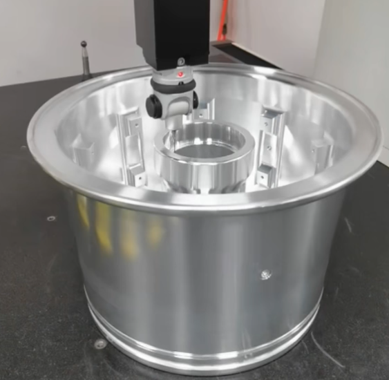
– Coordinate measuring machine (CMM) inspection for complex geometries
– Surface roughness measurements for critical surfaces
– Visual inspection for burrs, tool marks, and cosmetic consistency
– Functional checks of threads, fits, and assemblies
For parts with strict tolerance requirements, inspection results can be documented in reports that list measured values for key features. This helps engineers correlate test results with part geometry and identify any required design adjustments.
Cost Factors in CNC Prototype Machining
The cost of CNC-machined prototype parts is influenced by several elements:
– Material: Type, grade, and stock form (plate, bar, billet) affect raw material cost.
– Geometry complexity: Deep pockets, tight radii, or intricate contours increase machining time.
– Tolerances: Tight or geometric tolerances often require slower cutting parameters and more inspection.
– Quantity: Setup time per part decreases as quantity increases; single prototypes incur all setup cost on one piece.
– Finishing: Anodizing, polishing, plating, painting, and other finishes add process steps and handling.
– Special requirements: Thread standards, marking, serialization, or cleanliness requirements can add cost.
For rapid prototyping, cost optimization usually involves simplifying geometry where possible, relaxing tolerances on non-critical features, using readily available materials, and reducing the number of different setups and fixtures.
Considerations for Selecting a CNC Prototyping Partner
Selecting an appropriate CNC machining partner can significantly affect prototype quality and lead time. Useful considerations include:
– Experience with prototype work, not only production machining
– Capability range (3-axis, 5-axis, turning, mill-turn, and various materials)
– Ability to handle both metals and plastics used in your project
– Inspection capabilities and documentation practices
– Communication regarding manufacturability feedback, tolerances, and design adjustments
– Track record for on-time delivery and consistency across batches
An effective partner can provide feedback early in the process, suggesting design modifications that reduce machining time while preserving required function. This collaboration supports shorter design cycles and more predictable outcomes in rapid prototyping programs.
Frequently Asked Questions
Why use CNC machining for rapid prototyping?
CNC machining provides high accuracy, excellent surface finish, and production-grade materials, making it ideal for functional and mechanical prototypes.
Is CNC machining suitable for both functional and visual prototypes?
Yes, CNC machining is ideal for functional testing and can also produce high-quality visual prototypes with secondary surface finishing.
How does CNC rapid prototyping compare to 3D printing?
CNC machining offers stronger parts, tighter tolerances, and real-world materials, while 3D printing is better suited for early-stage form validation.
Can design changes be made during the prototyping process?
Yes, CNC machining allows quick design iterations with minimal tooling changes, supporting fast product development cycles.
