
Custom machining is the process of removing material from a workpiece to produce components that meet specific dimensional, geometric and functional requirements. It covers prototyping, small batch production and high-volume manufacturing across metals, plastics and advanced materials.
What Is Custom Machining
Custom machining refers to the use of machine tools and computer numerical control (CNC) systems to manufacture non-standard parts according to a customer’s drawings, models or technical specifications. Unlike standard catalog components, custom-machined parts are tailored to a particular application, assembly or performance requirement.
It is widely used in industries such as aerospace, automotive, medical devices, robotics, energy, instrumentation and general industrial equipment, where fit, function and reliability demand tight dimensional control and consistent quality.
Key Custom Machining Processes
Custom machining uses a variety of subtractive processes. Most projects combine more than one process to achieve the final geometry and surface finish.
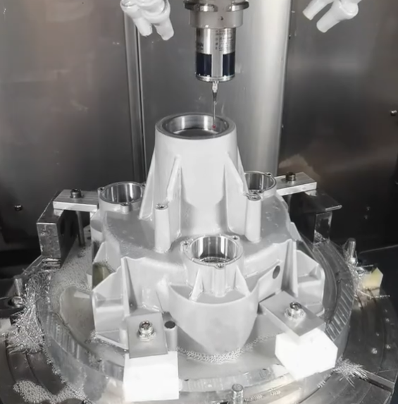
CNC Milling
CNC milling uses rotating cutting tools to remove material from a stationary or dynamically positioned workpiece. It is suited for prismatic parts, pockets, slots, contours and complex 3D surfaces.
- Typical axes: 3, 4 and 5-axis configurations
- Common operations: face milling, contouring, pocketing, drilling, tapping, thread milling
- Typical features: flat faces, pockets, cavities, bosses, holes, chamfers, fillets, threads
CNC Turning
CNC turning rotates the workpiece while a cutting tool moves linearly to generate round, symmetric components. It is efficient for shafts, pins, bushings and components with rotational symmetry.
- Common operations: OD/ID turning, facing, grooving, threading, boring, parting-off
- Typical features: cylindrical sections, tapers, grooves, undercuts, threads, shoulders
Multi-Axis and Mill-Turn Machining
Mill-turn and multi-axis machines combine milling and turning operations on one platform. This reduces setups and improves geometric relationships between complex features.
Applications include parts with mixed prismatic and rotational features, off-axis holes, angled features and complex 3D contours in a single clamping.
Other Common Machining Operations
Depending on the specification, a custom machining workflow can also include:
- Drilling, reaming and tapping for precise holes and threads
- Broaching for internal splines or keyways
- Grinding for tight tolerances and fine surface finishes
- Electrical discharge machining (EDM) for hard materials and sharp internal corners
- Honing and lapping for controlled micro-finishes and precise bores
Design Guidelines for Custom Machined Parts
Designing for machining efficiency can significantly influence cost, quality and lead time. Proper design guidelines help reduce machining time, tooling wear, scrap and rework.
Wall Thickness and Rigidity
Thin walls are more prone to vibration, deflection and dimensional drift.
Typical recommendations include:
- Minimum wall thickness for metals: about 0.8–1.0 mm for small features, thicker for large surfaces
- Minimum wall thickness for plastics: about 1.0–1.5 mm, depending on material stiffness
- Increase wall thickness or add ribs where rigidity is critical
Internal Radii and Corner Geometry
Sharp internal corners require small-diameter tools, which increase machining time and tool wear. Use generous radii where possible.
Practical rules include:
- Internal corner radius at least 1.5–3× the tool radius used
- Prefer uniform radii across similar features to simplify tooling
- Use reliefs or undercut features only when necessary and specify clearly
Holes, Threads and Features
Standardization reduces cost. Consider the following:
- Use standard drill sizes and standard thread forms (e.g., M, UNC, UNF) whenever possible
- Avoid very deep holes; maintain depth ≤ 8–10× hole diameter where feasible
- For blind tapped holes, allow clearance for tap run-out; specify thread depth and overall hole depth separately if critical
Tolerances and Geometric Dimensioning
Tolerances directly affect machining time and inspection effort. Avoid specifying tighter tolerances than necessary for function.
General recommendations:
- Use general tolerance blocks for non-critical features (for example, ±0.1 mm for non-critical dimensions)
- Use GD&T (Geometric Dimensioning and Tolerancing) for critical relationships like flatness, perpendicularity, concentricity and position
- Complete datum schemes to clearly define how the part is located and measured
Fixturing and Accessibility
Design parts that can be securely clamped and fully accessed by cutting tools.
- Avoid deep, narrow cavities that limit tool access
- Provide flat reference surfaces for fixturing when possible
- Minimize required re-clamping operations by grouping features into accessible orientations
Capabilities: Dimensions, Tolerances and Finishes
Custom machining capabilities vary by shop and equipment. However, there are typical ranges for part size, tolerance and surface finish that are achievable with standard CNC machines and tooling.
| Capability Aspect | Typical Range | Notes |
|---|---|---|
| Maximum part size (milling) | Up to 1000 × 600 × 500 mm | Depends on machine travel and setup |
| Maximum part length (turning) | Up to 500–1500 mm between centers | Longer parts may need steady rests |
| Diameter range (turning) | Approx. 2–400 mm | Micro-turning and large-diameter turning are specialized |
| General dimensional tolerance | ±0.05–0.1 mm | Standard for non-critical features |
| Precision tolerance with finishing | ±0.005–0.01 mm | Requires precision setups and inspection |
| Hole location accuracy | ±0.02–0.05 mm | Achievable on well-calibrated CNC mills |
| Surface roughness (milled/turned) | Ra 0.8–3.2 μm | Standard finishing cuts and suitable tooling |
| Fine surface finish (ground) | Ra 0.1–0.4 μm | Requires grinding or lapping processes |
| Thread size range | Approx. M2–M64 or 2-56 to 2.5" | Smaller or larger with specialized tooling |
Note: These ranges are illustrative; actual capabilities depend on the specific machining provider, machine tool, fixturing method and metrology setup.
Materials Used in Custom Machining
Material selection affects machinability, achievable tolerance, surface finish, mechanical performance and cost. Common material classes are metals, plastics and advanced materials.
Metals
Metals are widely used for load-bearing and high-temperature components.
- Aluminum alloys (e.g., 6061, 6082, 7075): good machinability, high strength-to-weight ratio, widely used in structural and housing components
- Carbon steels (e.g., 1018, 1045): good strength, weldability and cost effectiveness
- Alloy steels (e.g., 4140, 4340): higher strength and toughness; often heat-treated
- Stainless steels (e.g., 303, 304, 316, 17-4PH): corrosion resistance and moderate to high strength
- Copper and brass: excellent electrical conductivity and machinability, used in electrical and fluid fittings
- Titanium alloys (e.g., Ti-6Al-4V): high specific strength and corrosion resistance
Plastics
Plastics are suitable for lightweight, corrosion-resistant and electrically insulating components.
- ABS, PVC, HDPE: general-purpose plastics for enclosures and non-structural parts
- Nylon, acetal (POM): engineering plastics with good wear resistance and dimensional stability
- PEEK, PTFE, PPS: high-performance plastics for elevated temperatures and demanding environments
Advanced and Difficult-to-Machine Materials
Custom machining can be applied to hardened steels, nickel-based alloys, ceramics (with grinding), and composites. These materials may require specialized tooling, lower cutting speeds and dedicated process controls.
Surface Finishes and Post-Processing
Surface finish is critical for sealing surfaces, sliding components and aesthetic parts. Post-processing steps may be mechanical, chemical or thermal.
As-Machined Surface
As-machined surfaces from CNC milling and turning are generally adequate for many functional applications. Typical surface roughness is Ra 1.6–3.2 μm depending on cutting parameters and tooling.
Mechanical Finishing
Mechanical processes modify the surface through removal or plastic deformation:
- Grinding: improves dimensional accuracy and surface finish, common for shafts, bearing surfaces and precision faces
- Honing and lapping: refine bore geometry and achieve very low surface roughness
- Polishing: enhances aesthetics and reduces surface roughness
Chemical and Electrochemical Finishing
Common finishes include:
- Anodizing for aluminum (e.g., clear, black, colored): increases corrosion and wear resistance
- Passivation for stainless steel: removes free iron and enhances corrosion resistance
- Plating (e.g., zinc, nickel, chrome): improves appearance, wear resistance or electrical properties
Heat Treatment
Heat treatment modifies the mechanical properties of metals.
- Quenching and tempering to increase hardness and strength
- Solution treatment and aging for precipitation-hardened alloys
- Stress relieving after machining to reduce residual stress and distortion
Cost Drivers in Custom Machining
Understanding the primary factors that drive machining costs helps in designing cost-effective parts and evaluating quotations.
| Cost Driver | Impact on Cost | Typical Considerations |
|---|---|---|
| Material type | Medium to high | Raw material price, machinability, required tooling, tool wear |
| Part complexity | High | Number of features, 3D contours, small radii, deep pockets, undercuts |
| Tolerances | High | Tight tolerances require lower cutting speeds, more passes and detailed inspection |
| Surface finish | Medium | Fine finishes increase time and may require secondary processes |
| Quantity | High | Setup cost amortized over batch size; higher volumes may justify dedicated tooling |
| Setup and fixturing | Medium | Number of setups, complexity of fixtures, changeovers |
| Material removal volume | Medium | Time required to remove stock, especially for large blocks and deep cavities |
| Post-processing | Medium | Heat treatment, coating, grinding, polishing and associated logistics |
| Quality and documentation | Medium | Inspection level, measurement reports, certificates, traceability |
Typical Cost Ranges and Estimation Basics
Machining costs are generally a function of material cost plus machine time, setup, programming and overhead. While precise pricing is specific to each provider and location, understanding the main components assists in early-stage budgeting.
Components of Machined Part Cost
Key cost components include:
- Raw material: price of bar, plate, block or billet, including waste factors
- Programming: CAM programming and process engineering time
- Setup: machine setup, fixturing and tooling adjustments
- Machining time: cutting, tool changes, probing and in-process inspection
- Tooling: standard and special tools, inserts and tool wear
- Post-processing: finishing, heat treatment, coating, marking
- Inspection and documentation: measurement, reports and certifications
Relative Cost Profiles
As a general guideline:
- Simple prototypes in aluminum with standard tolerances are among the lowest cost categories
- Multi-axis machined parts with tight tolerances and high-performance materials fall into higher cost categories
- Higher quantities reduce per-unit cost through amortization of setup and programming
Typical Issues and Practical Considerations
Custom machining often involves specific constraints that influence design and procurement decisions.
Dimensional Stability and Distortion
Removal of large amounts of material, especially from long or thin sections, can induce warping or distortion due to residual stresses or insufficient rigidity. This can require intermediate stress relief, optimized toolpaths or revised part geometry.
Feature Accessibility
Deep cavities, small internal radii and complex undercuts may demand specialized tooling, additional setups or processes such as EDM. This increases machining time, complexity and cost.
Lead Time Constraints
Tight delivery dates combined with specialized materials, complex components or extensive post-processing steps can constrain scheduling. Forward planning for material availability, heat treatment capacity and finishing queues helps avoid delays.
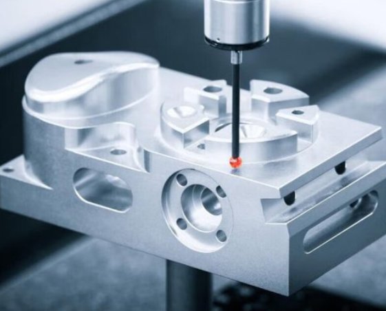
Quality Control and Inspection
Consistent quality in custom machining relies on appropriate inspection methods, calibrated instruments and documented procedures.
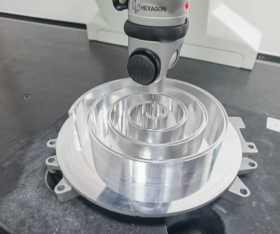
Dimensional Inspection
Standard inspection methods include:
- Hand tools: calipers, micrometers, height gauges, bore gauges
- Coordinate Measuring Machines (CMM): for complex geometries and GD&T checks
- Optical measurement: profile projectors, vision systems and laser scanners
Material and Process Certification
For regulated or safety-critical applications, additional documentation may be required:
- Material certificates and traceability (e.g., mill test reports)
- Heat treatment and surface treatment certificates
- First Article Inspection (FAI) reports and capability studies
Statistical and Process-Based Controls
To maintain consistency over batches, some machining providers apply statistical process control, tool life monitoring and documented work instructions. These measures help ensure repeatability and reduce variability.
DFM: Designing for Machining Efficiency
Design for Machining (DFM) focuses on aligning part design with machining capabilities to lower cost and improve manufacturability.
Simplifying Geometry
Reduce non-functional complexity by:
- Minimizing unnecessary contouring, very small features and deep, narrow pockets
- Using uniform wall thicknesses where possible
- Combining features into fewer operations when they share a common orientation
Aligning Features to Standard Tools
Match radii, hole sizes, thread types and chamfers to commonly available tool sizes. This reduces tool change frequency, tooling cost and programming time.
Balancing Tolerance with Function
Assign tight tolerances only where function, fit or performance demands it. Use broader tolerances and general notes for non-critical attributes, which can significantly lower machining and inspection effort.
RFQ and Supplier Selection
Requesting quotations (RFQs) and selecting machining suppliers are critical steps in obtaining suitable quality and cost for custom parts.
Effective RFQ Packages
An effective RFQ includes:
- Fully dimensioned drawings and/or 3D models with clear revision levels
- Specified material grade, condition and any equivalents acceptable
- Tolerances, surface finish requirements and GD&T information
- Quantity, delivery schedule and any batch breakdown
- Post-processing requirements: heat treatment, coating, marking, assembly
- Quality expectations: inspection level, reports, certificates
Criteria for Selecting a Machining Provider
When choosing a supplier, consider:
- Technical capabilities: machine types, axis count, size limits, materials handled
- Experience with similar components or industries
- Quality systems and certifications if required (for example, ISO-based systems)
- Lead time reliability and communication practices
- Capacity for prototyping, engineering support and scaling to higher volumes
Application Areas of Custom Machining
Custom machining is used wherever non-standard components are required with controlled geometry and material properties.
Aerospace and Defense
Applications include structural brackets, housings, manifolds, landing gear components and precision fixtures in aluminum, titanium and nickel-based alloys. Requirements often include tight tolerances, controlled surface finishes and extensive documentation.
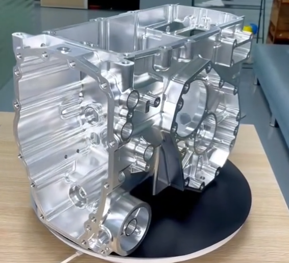
Automotive and Transportation
Custom-machined parts are used in powertrain components, suspension hardware, steering assemblies, braking systems, test fixtures and motorsport applications. Materials range from aluminum and steel to special alloys and composites.
Medical Devices and Equipment
Machined components include surgical instruments, implant components (where applicable regulatory requirements are met), diagnostic equipment parts and laboratory fixtures. These often demand high surface quality, biocompatible materials and repeatable precision.
Industrial Equipment and Automation
Examples include machine frames, adapter plates, precision shafts, couplings, robotic end effectors, tooling and dies. Requirements vary from robust, cost-effective parts to high-precision motion control components.
Working With Tolerances and Fits
Appropriate fits and tolerances ensure that mating components operate correctly without excessive clearance or interference.
Clearance, Transition and Interference Fits
Fits can be classified as:
- Clearance fits: sliding or running fits for shafts and holes
- Transition fits: controlled clearance or slight interference for precise location
- Interference fits: permanent or semi-permanent assemblies where press-fit is required
Specifying Fits on Drawings
Use standard fit systems where possible (for example, indicating hole and shaft tolerances in a coordinated system). Ensure that machining capabilities and inspection methods are consistent with the required fits.
Prototyping vs Production Machining
Custom machining is often used across the product life cycle, from concept validation to full production.
Prototype Machining
Prototyping focuses on speed, flexibility and design iteration. Choices often include:
- Machining from easily available materials and stock sizes
- Using general tolerances where precise control is not yet required
- Minimizing cosmetic finishing to shorten lead time
Low-Volume and Production Machining
Production machining emphasizes repeatability, cost efficiency and stable processes.
- Dedicated fixtures and optimized toolpaths to reduce cycle time
- Process documentation and in-process inspection to maintain consistency
- Batch-level material management and traceability as required
Logistics, Packaging and Documentation
Downstream aspects of machining can influence overall project success, particularly for high-value or delicate parts.
Packaging and Handling
To protect machined surfaces and geometry:
- Use appropriate protective materials (for example, foam, separators, caps)
- Isolate critical surfaces from potential impact or abrasion
- Control humidity and corrosion risk for susceptible metals with suitable packaging
Labels and Documentation
Clear labeling and documentation assist in traceability and quality control.
- Part number, revision, quantity and batch identification
- Inspection reports, material certificates and treatment records where necessary
- Special handling or storage instructions if applicable
Summary
Custom machining provides flexible, precise manufacturing for components with specific geometry, tight tolerances and demanding material requirements. By understanding machining processes, capabilities, design guidelines, cost drivers and quality practices, engineers and buyers can specify parts that meet functional requirements while managing cost and lead time.
FAQ
What is custom machining?
Custom machining is the process of manufacturing parts based on customer-specific designs, drawings, or CAD models, using CNC or manual machining methods to meet exact functional and dimensional requirements.
How is pricing calculated for custom machining projects?
Pricing is typically based on material cost, machine time, tooling requirements, labor, quality inspection, and finishing operations.
How do you ensure quality in custom machining?
Quality is ensured through process control, in-process inspection, CMM measurement, material certification, and adherence to ISO quality management standards.
How do I choose between CNC machining and other manufacturing methods?
CNC machining is suitable when you need high dimensional accuracy, moderate to low production volumes, complex geometries in metals or plastics, or when design changes are expected. Alternatives such as casting, forging or additive manufacturing may be more appropriate for different volume levels, design constraints or material structures. It is common to combine processes, for example, machining critical surfaces on a casting or forging.
