
Surface finish is a critical characteristic of manufactured parts that directly affects performance, fit, function, and appearance. Understanding how to define, measure, and specify surface finish is essential in machining, fabrication, precision engineering, and quality control.
Definition of Surface Finish and Surface Texture
Surface finish is the overall condition of a surface resulting from a manufacturing process. It describes the small-scale variations in height, spacing, and shape on the surface of a part, typically over a limited evaluation length.
In technical standards, the broader term often used is surface texture, which consists of three main components:
- Roughness: Fine, closely spaced deviations from the nominal surface, mainly due to the manufacturing process (tool marks, feed marks, abrasive tracks).
- Waviness: More widely spaced surface deviations with larger wavelength than roughness, often caused by machine deflection, vibration, heat distortion, or misalignment.
- Form (or Shape): Long-range deviation from the ideal geometric form, such as bow, warpage, taper, and out-of-roundness.
Surface finish, in many industrial contexts, is used almost synonymously with surface roughness, but formally it is influenced by all three components. When specifying or measuring, it is important to distinguish which aspect is being controlled.
Key Concepts: Roughness, Lay, and Waviness
Several concepts are used to characterize surface finish in a complete way.
Roughness
Roughness describes the small, frequent deviations of the surface from a perfectly smooth profile. It is usually quantified by numerical parameters such as Ra, Rz, or Rq, calculated from a measured profile after filtering out longer wavelength components (waviness and form).
Lay
Lay is the predominant direction of the surface pattern. It is mainly determined by the process:
- Turning: Lay is typically circumferential, following the tool path.
- Milling: Lay may be transverse or cross-hatched, depending on cutter path and strategy.
- Grinding: Lay is usually parallel to the grinding direction.
- Lapping or superfinishing: Lay may be very fine or multi-directional.
On engineering drawings, lay is indicated by standardized symbols, because the direction of surface pattern can significantly influence friction, sealing, fatigue, and wear.
Waviness
Waviness refers to the more widely spaced irregularities with wavelengths exceeding those considered as roughness. It arises from factors such as machine tool vibration, imbalance, drive irregularities, thermal effects, or workpiece deflection.
Waviness is characterized by parameters similar to roughness (for example Wt, Wz, Wa) but evaluated with different filters and cut-off lengths. In critical applications, both roughness and waviness must be controlled to ensure stable performance.

Why Surface Finish Matters in Engineering
Surface finish has measurable effects on the function and reliability of components. When surface finish is not correctly specified or controlled, it can lead to performance loss, increased wear, or even early failure.
Functional Impact
Key performance areas affected by surface finish include:
- Friction and wear: Smoother surfaces generally reduce friction in lubricated systems, but overly smooth surfaces may inhibit lubricant retention. Rough surfaces can increase wear by creating micro-cutting and abrasive contact.
- Fatigue strength: Surface irregularities act as stress concentrators. Poor surface finish can significantly reduce fatigue life of rotating shafts, springs, and structural components.
- Sealing and leakage: Mating surfaces of seals, flanges, or valve seats need appropriate roughness to balance tight sealing with adequate lubricant or media retention.
- Contact resistance: In electrical contacts, finish influences true contact area, affecting conductivity, stability, and heat generation at interfaces.
- Corrosion behavior: Rough surfaces with micro-crevices may trap corrosive media and accelerate localized attack, while some textures may promote protective film formation depending on material and environment.
- Lubrication and film formation: Surface finish controls oil film stability, particularly in bearings, sliding guides, and hydraulic components.
Assembly, Fit, and Dimensional Control
Surface finish affects:
Dimensional accuracy and effective size: The actual contact between parts may differ from nominal dimensions if surfaces are rough. In precision fits, surface finish must be compatible with tolerance classes to avoid interference or excessive clearance.
Surface integrity: Manufacturing processes that create very low roughness may also introduce residual stresses or surface damage. Thus, finish must be considered in conjunction with process choice and heat treatment.
Appearance and Aesthetics
For visible components, surface finish influences perceived quality. Consistent finish with controlled gloss, reflectivity, and texture is often a requirement for consumer products, vehicle interiors, decorative hardware, and architectural elements. In such cases, numerical parameters are combined with visual standards and sample panels.
Common Surface Finish Parameters and Their Meaning
Surface finish is quantified by standardized parameters defined in international standards such as ISO 4287, ISO 4288, ISO 25178, and related documents. The most used parameters for profile measurements include Ra, Rz, Rq, and Rt.
| Parameter | Type | Definition (Conceptual) | Typical Use |
|---|---|---|---|
| Ra | Arithmetic average roughness | Arithmetic mean of the absolute values of profile deviations from the mean line over the evaluation length. | Most widely used general roughness indicator; simple and robust. |
| Rz | Average maximum height | Average of the vertical distance between the highest peak and lowest valley within each sampling length, over several sampling lengths. | Gives better sense of peak-to-valley height than Ra; useful where peak heights are critical. |
| Rt (or Rmax) | Total height | Vertical distance between the highest peak and lowest valley in the entire evaluation length. | Indicates extreme peak or defect; sensitive to isolated irregularities. |
| Rq | Root mean square roughness | Square root of the mean of squared deviations from the mean line over the evaluation length. | Statistical measure; more sensitive to outliers than Ra; used in research and optics. |
| Rsk | Skewness | Statistical measure indicating symmetry of the profile height distribution around the mean line. | Distinguishes surfaces dominated by peaks (positive) or valleys (negative). |
| Rku | Kurtosis | Measure of how sharp or flat the height distribution is compared to a normal distribution. | Used to detect spiky or plateau-like surfaces. |
For area (3D) measurements, the analogous parameters are Sa, Sz, Sq, and others defined in ISO 25178, calculated from a surface map instead of a single profile.
Units and Typical Surface Roughness Ranges
Surface roughness parameters are usually expressed in micrometers (µm), sometimes in microinches (µin) in certain industries.
Typical roughness ranges associated with common manufacturing processes are shown below. These are indicative ranges and may vary with material, tooling, process conditions, and measurement method.
| Process | Approximate Ra Range (µm) | Notes |
|---|---|---|
| Sand casting | 3.2 – 25 | Relatively rough; secondary machining often required for functional surfaces. |
| Die casting | 1.6 – 6.3 | Finer than sand casting; finish influenced by die condition and lubricant. |
| Flame or plasma cutting | 6.3 – 25 | Typically followed by machining or grinding for critical surfaces. |
| Sawing | 3.2 – 12.5 | Used for preliminary cuts; not usually a final functional finish. |
| Conventional turning | 0.8 – 6.3 | Dependent on feed, nose radius, tool condition, and material. |
| Milling | 0.8 – 3.2 | Finer feeds and better tool geometry reduce roughness. |
| Drilling | 1.6 – 6.3 | Finish affected by drill geometry and cutting conditions. |
| Reaming | 0.4 – 1.6 | Improves hole size accuracy and surface finish. |
| Broaching | 0.4 – 1.6 | Capable of consistent finish along complex profiles. |
| Grinding | 0.1 – 1.6 | Common for precision surfaces and tight tolerances. |
| Honing | 0.05 – 0.4 | Produces controlled cross-hatch pattern, often for cylinders. |
| Lapping / superfinishing | 0.01 – 0.1 | Used where very low roughness and high precision are required. |
| Polishing (mechanical) | 0.02 – 0.2 | Gives smooth and often reflective finish; numerical values depend on method. |
Surface Finish Symbols on Engineering Drawings
Engineering drawings use standardized symbols to indicate required surface finish, as defined in standards such as ISO 1302 or ASME Y14.36. Understanding these symbols is important to ensure the intended finish is achieved and correctly inspected.
Basic Symbol and Modifiers
The basic symbol is a check-mark-like symbol consisting of two legs. It can be modified to convey additional information:
- Basic symbol alone: Surface texture requirement without specifying whether material removal is required.
- Symbol with a bar across the top leg: Material removal required by machining or other methods.
- Symbol with a circle at the junction: Material removal is not permitted (for example, as-cast or as-forged surfaces).
Additional information is placed around the symbol:
Roughness value: Typically Ra (for example, 1.6) is placed above or adjacent to the symbol. Other parameters (Rz, Rmax) may also be specified when necessary.
Machining allowance, lay direction, and sampling length are added as indicated in the relevant standard. Consistent use of these symbols ensures that design intent is clearly communicated to manufacturing and inspection.
Methods of Measuring Surface Finish
Surface finish measurement is performed to verify that surfaces meet specified requirements and to control manufacturing processes. Methods can be broadly divided into contact and non-contact techniques.
Contact Stylus Profilometers
Stylus profilometers are among the most widely used instruments in industry. A diamond-tipped stylus travels across the surface under controlled force, and vertical movements are recorded as a function of horizontal position, forming a profile.
Key aspects include:
Stylus tip radius: Common radii range from about 2 µm to 10 µm. Smaller tips detect finer detail, but may be more sensitive to damage and contamination.
Evaluation length and sampling length: The instrument measures across several sampling lengths (for example, five) to produce parameters over an evaluation length according to standards such as ISO 4288.
Filtering: Digital filters (Gaussian or other types) are applied to separate roughness from waviness and form. Choice of cut-off length strongly influences measured values.
Non-Contact Optical Methods
Non-contact methods use light or other radiation to obtain surface profiles or area maps. Common approaches include:
White light interferometry: Uses interference of light reflected from the surface to obtain high-resolution 3D surface maps, suitable for smooth surfaces and precision optics.
Confocal microscopy: Uses optical sectioning to measure surface heights point-by-point or line-by-line, effective for complex surfaces and microstructures.
Focus variation and structured light: Techniques that derive height information from changes in focus or patterns projected onto the surface, suitable for rough or steep surfaces where interferometry may be limited.
Optical methods provide fast, detailed 3D data but may be sensitive to surface reflectivity, transparency, and contamination.
Other Techniques
In addition to stylus and optical methods, the following techniques may be used in specific contexts:
Replica methods: A replica material is applied to the surface and, once cured, is measured under magnification or with a profilometer. Useful for large or inaccessible parts.
Scanning electron microscopy (SEM): Provides high-resolution imaging of surface morphology. While not a standard production measurement tool for roughness parameters, it is valuable for analysis of wear, damage, and micro-geometry.
Atomic force microscopy (AFM): Used for extremely fine surfaces at the nanometer scale, for example, in microelectronics or precision optics, where conventional profilometers lack the required resolution.
Standardization and Surface Metrology Standards
Surface finish requirements and measurement procedures are governed by international and regional standards to ensure consistency among designers, manufacturers, and inspectors.
Key standards include:
ISO 4287: Defines surface texture parameters for profile methods, including Ra, Rz, Rt, and others.
ISO 4288: Specifies rules and procedures for measurement and assessment of surface texture, including selection of sampling and evaluation lengths.
ISO 1302: Specifies graphical symbols and indications for surface texture on technical drawings.
ISO 25178: Defines surface texture parameters for areal (3D) measurement, replacing some older 2D-focused standards for certain applications.
ASME and national standards: Various documents such as ASME B46.1 define corresponding requirements for North American practice, largely aligning with ISO concepts but using some different notation or parameter definitions.
Practical Considerations When Specifying Surface Finish
Properly specifying surface finish helps balance performance, manufacturability, and cost. Poorly defined or unrealistic finish requirements can result in unnecessary process steps, higher cost, or difficulty meeting specifications.
Selecting Appropriate Parameters
Common practice is to specify Ra as the primary parameter. However, relying on Ra alone may be insufficient if surface function is sensitive to peak heights or valleys. For example:
In sealing applications, maximum peak-to-valley height (Rz or Rt) may be relevant to avoid leakage paths.
In bearing surfaces, plateau-like surfaces with controlled valleys may require additional parameters related to bearing area (for example, Rmr or functional parameters defined in ISO 13565 or ISO 25178).
Choosing the right parameter set helps ensure that surfaces perform as intended, not just that they meet a nominal Ra value.
Matching Finish to Function and Process
Surface finish requirements should be compatible with the selected manufacturing process and tolerance level. For example:
Primary structural surfaces may be adequately specified with moderate roughness achievable by turning or milling.
Precision sliding surfaces, hydraulic components, and bearing seats may require grinding, honing, or lapping to achieve the necessary combination of roughness and geometric accuracy.
Optical surfaces, sealing faces, and high-precision mechanical interfaces may demand finishes only achievable by specialized processes and controlled polishing.
Measurement Strategy and Control
To effectively control surface finish in production, it is important to define:
Measurement locations: Where on the part the finish will be verified, especially if finish may vary across the surface due to process conditions.
Measurement direction: Orientation relative to lay, as measurements taken parallel or perpendicular to the lay can yield different parameter values.
Sampling strategy: Number of parts and measurements per part needed to characterize process capability and ensure compliance with specifications.
Common Issues Related to Surface Finish
Several typical issues can arise in practice:
Insufficiently defined requirements: Only a general Ra value is specified without stating parameter type, filter settings, or sampling length, leading to inconsistent measurement results.
Overly tight requirements: Surface finishes tighter than necessary for function can increase machining time, tool wear, and inspection effort without tangible benefit.
Mismatch between finish and material: Some materials are more difficult to machine to low roughness (for example, hardened steels, certain alloys). Requirements must consider material machinability and process constraints.
Inconsistent measurement methods: Different instruments or settings used by supplier and customer may produce non-comparable results. Aligning standards, instruments, and procedures is essential.
Surface Finish in Relation to Tolerances and Geometric Accuracy
Surface finish is one part of the broader dimensional and geometric specification of a component. While tolerances control size and shape, surface finish controls the fine detail of the surface profile.
Important relationships include:
Interdependence with dimensional tolerances: Rough surfaces effectively alter the actual contact dimensions when parts are assembled. Very tight dimensional tolerances with rough surfaces may cause interference or unpredictable fit.
Link to geometric tolerances: Features such as flatness, cylindricity, or circularity describe deviations at larger scale. A surface can meet roughness requirements but fail flatness or vice versa. Both must be considered in functional design.
Surface integrity: Beyond roughness, manufacturing processes can induce micro-cracks, residual stresses, microstructural changes, and hardness variations. Comprehensive control of surface integrity is often needed in high-stress or safety-critical parts.

Guidelines for Engineers and Manufacturers
To use surface finish specifications effectively, engineers and manufacturing personnel can apply the following guidelines:
Define finish in terms of function: Begin from functional requirements (friction, sealing, fatigue, appearance) and work back to appropriate parameters and values.
Use standards consistently: Adopt internationally recognized standards for symbols, parameters, and measurement procedures, and ensure all involved parties follow the same references.
Align finish with process capability: Consult with manufacturing and suppliers to confirm that specified finishes are achievable with available processes and cost constraints.
Specify location and direction: Indicate where on the part surface finish must be measured and along which direction relative to lay.
Document measurement conditions: Record instrument type, stylus tip, filter settings, sampling lengths, and evaluation methods to make results reproducible and comparable.
FAQ: Surface Finish and Roughness
What is surface finish?
Surface finish refers to the texture and quality of a material’s surface after manufacturing, including roughness, waviness, and lay.
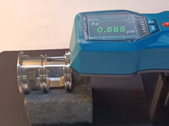
How is surface finish measured?
Surface finish is commonly measured using parameters such as Ra, Rz, and Rt with tools like profilometers or surface roughness testers.
What are common surface finish types?
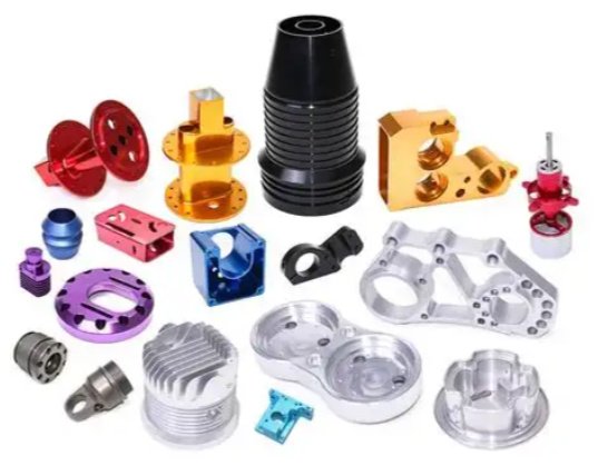
Common surface finishes include polished, brushed, anodized, electroplated, powder-coated, and bead-blasted finishes.
What is the difference between surface finish and surface roughness?
Surface roughness is a component of surface texture that quantifies short-wavelength deviations from the ideal surface using numerical parameters such as Ra or Rz. Surface finish is a broader term commonly used in industry that often refers to the visual and functional quality of a surface, influenced by roughness, waviness, lay, and sometimes form and surface integrity.
How do I choose the right surface finish value for a part?
Selection should be based on the part’s function, load, motion, and environment, as well as the manufacturing process capability. Reference to established design guidelines, past successful designs, and relevant standards can help. In many cases, using the coarsest finish that still meets functional requirements is a cost-effective approach.
