
A Coordinate Measuring Machine (CMM) is a precision metrology system that determines the coordinates of points on a workpiece surface in a defined 3D coordinate system, allowing accurate dimensional, geometric and form inspection. This guide covers CMM fundamentals, types, components, probes, accuracy, programming, applications, selection and maintenance in a systematic and technical way.
Fundamental Concepts of CMM Metrology
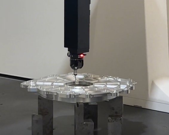
A CMM measures the geometry of physical objects by sensing discrete points on the surface with a probe and expressing these points in a defined coordinate system. From these points, the machine software reconstructs features and dimensions such as lengths, diameters, angles, position and form deviations.
The basic elements of CMM metrology are:
- A fixed or movable structure that defines a machine coordinate system (MCS).
- A probing system that establishes contact or non-contact points with the workpiece.
- A workpiece coordinate system (WCS) aligned to datums on the part.
- Software that computes feature geometry and tolerance conditions.
Measurement results depend on the traceability of the CMM scale system to length standards and on the correct establishment of datums. The CMM enables quantitative assessment of size, form, orientation and location tolerances defined by engineering drawings and GD&T standards.
How a CMM Works: Measurement Principles
The CMM determines coordinates by reading high-resolution scales along its axes, combined with probe trigger or distance information.
Typical measurement sequence:
- The probe is moved toward the surface manually or under CNC Quality control.
- For contact probing, a trigger event or deflection threshold is detected when the stylus touches the part.
- For optical or scanning systems, distance or image information is converted into coordinates.
- The machine controller reads the scale positions (X, Y, Z) at trigger time and records a point.
- Multiple points on a feature are fitted using mathematical algorithms (least-squares, minimum zone, etc.).
Coordinate transformations align raw machine coordinates to the workpiece coordinate system through a defined alignment procedure, typically using datum planes, lines and points. Once alignment is established, the CMM can report dimensions and deviations relative to the drawing reference frame.
Main Types of CMM Structures
CMMs are available in multiple structural configurations optimized for different measurement ranges, precision levels and workshop conditions.
Bridge CMM
Bridge CMMs are the most widely used type for high-accuracy inspection in controlled environments. The bridge spans the granite or ceramic table, with one leg fixed and the other moving along the base axis. The crossbeam carries the Z-axis and the probe head.
Typical characteristics:
- High rigidity and good thermal stability.
- Measurement ranges from small (e.g. 500 × 400 × 400 mm) to large (e.g. 2000 × 3000 × 1500 mm).
- Suitable for prismatic parts, precision components, mold and die inspection.
Gantry CMM
Gantry CMMs are designed for large and heavy workpieces, such as aerospace structures, automotive body-in-white, and large dies. The bridge is elevated on columns, allowing the part to be loaded from the sides or above.
Key points:
Large measuring volumes, often exceeding 4000 mm in a single axis, and high load capacity. They are usually installed on dedicated foundations and often equipped with environmental control systems around the measuring volume.
Cantilever CMM
Cantilever CMMs have a horizontal arm supported on one side only, which enables very good accessibility from three sides. The part usually rests on a fixed table, and the arm extends over it.
These systems are common for measuring smaller components, especially in production areas where quick part loading and operator access are priorities. Mechanical design must compensate for bending and deflection of the cantilever arm to maintain accuracy.
Horizontal Arm CMM
Horizontal arm CMMs use a horizontally moving spindle mounted on a column or rail system. They are widely used in automotive and sheet metal inspection (body-in-white, closures, interiors) and for large plastic or composite parts.
They may be table-mounted or floor-installed; dual-arm configurations are common for measuring large assemblies. Although absolute accuracy is typically lower than high-end bridge CMMs, they excel in accessibility and integration into production lines.
Portable and Articulated Arm CMM
Portable CMMs, especially articulated arm CMMs, provide flexibility for on-site measurement of large components, assemblies or fixtures. The articulated arm has several rotary joints equipped with high-resolution encoders, and the probe at the end records 3D coordinates.
They are commonly used on shop floors, in tooling workshops and for alignment tasks. Measurement range is limited by arm reach, and accuracy is affected by arm pose, temperature and operator handling.
Optical and Vision CMM
Optical CMMs, including multisensor and vision systems, use cameras, lasers or structured light sensors instead of or in addition to contact probes. They are suitable for small, delicate parts, micro-features, soft materials and parts requiring dense point clouds.
Integration of tactile and optical sensors in one machine allows measurement of diverse features, such as deep bores with tactile probes and fine edge details with vision or laser sensors.
Comparison of Major CMM Types
| Type | Typical Use | Measurement Volume (approx.) | Accuracy Level (relative) | Key Advantages |
|---|---|---|---|---|
| Bridge CMM | General precision inspection | Up to ~2000 × 3000 × 1500 mm | High | Good accuracy, stability, widely supported |
| Gantry CMM | Large and heavy parts | Often > 4000 mm in at least one axis | Medium to high | Large capacity, overhead access |
| Cantilever CMM | Small to medium parts, open access | Typically up to ~1000 mm in main axes | Medium to high | Three-side access, operator friendly |
| Horizontal Arm CMM | Body-in-white, sheet metal, large assemblies | Extended in-plane reach, height depends on column | Medium | Excellent accessibility, inline integration |
| Articulated Arm CMM | Portable on-site measurement | Limited by arm length (e.g. 1.2–4.5 m reach) | Low to medium | Portable, flexible positioning |
| Optical / Vision CMM | Small, delicate or complex-surfaces parts | Typically small to medium volume | Medium to high (feature dependent) | Non-contact, high-density data |
Core Components of a CMM System
A complete CMM system consists of mechanical, metrological, electronic and software elements that must be designed and configured as a coherent system.
Mechanical Structure and Guideways
The mechanical structure includes the base, table, bridge or arm, columns and moving axes. Materials often used are granite, ceramic, steel and aluminum alloys. The design must ensure low deformation, controlled thermal expansion and vibration damping.
Guideways (air bearings on granite or ceramic surfaces, or mechanical bearings) provide smooth, low-friction movement. Air bearings are widely used on precision bridge CMMs for near-zero friction and low hysteresis. Straightness and perpendicularity of guideways directly influence geometric accuracy.
Scale Systems and Encoders
Linear scales along each axis provide the fundamental position measurement. High-end CMMs use optical or interferometric scales with resolutions down to sub-micrometer or even nanometer levels. The controller interpolates scale signals to provide continuous position feedback.
Important parameters include scale resolution, accuracy, thermal expansion coefficient and mounting method. The scales must be stable relative to the structure and compensated for temperature effects to maintain traceable measurements.
Probe Heads and Stylus Systems
The probe head holds the probe and connects it to the CMM quill or spindle. Probe heads can be fixed or indexable, manual or motorized. Motorized heads allow automatic reorientation to measure features at different angles without repositioning the part.
Stylus systems include stylus bodies and tips, often made of ceramic or stainless steel with ruby or silicon nitride balls. Stylus stiffness, length and ball diameter influence measuring uncertainty and the ability to reach narrow features.
Controllers and Electronics
The CMM controller coordinates axis motions, probe signals, scale readings and safety functions. It executes motion commands from the measurement software, manages acceleration and deceleration, and monitors performance parameters.
Electronics include signal conditioning for scales, probe interface modules, temperature sensors and environmental monitoring devices. Communication with the host computer is typically via Ethernet or high-speed fieldbus connections.
Metrology and Inspection Software
CMM software is responsible for part program creation, execution, feature construction, GD&T evaluation and reporting. It provides graphical representation of the part and probe path, and it handles coordinate systems, alignments and transformations.
Key software functions include:
- CAD model import and CAD-based programming.
- Feature fitting (planes, cylinders, cones, spheres, freeform surfaces).
- GD&T tolerance evaluation per relevant standards.
- Statistical process control (SPC) interfaces and data export.
CMM Probing Technologies
Probing technology is a central factor in CMM capability. Different probe types are used depending on accuracy requirements, part geometry and material properties.
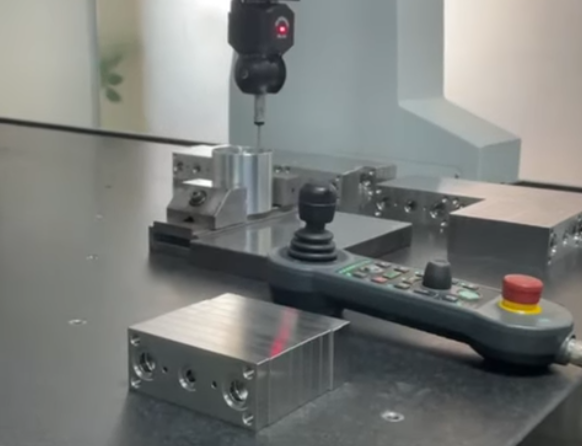
Touch Trigger Probes
Touch trigger probes generate a signal when the stylus makes contact with the part, capturing a single point per touch. They are widely used due to simplicity and good repeatability.
Operating principle typically involves a kinematic seat arrangement. When the stylus deflects beyond a threshold, electrical contacts open or close, triggering a measurement. After each point, the probe resets to its rest position.
They are effective for single-point features, hole patterns and general dimensioning, but they are less suitable for high-speed continuous scanning of form surfaces.
Analog and Scanning Probes
Analog or scanning probes are designed for continuous contact with the surface, collecting point streams rather than single points. Probe deflection is measured continuously using strain gauges or other sensors, enabling high-density profiles.
This capability is valuable for form analysis of gears, camshafts, turbine blades, freeform surfaces and other geometry where profile and waviness must be quantified. Control of contact force and scanning speed is critical to avoid distortions.
Fixed and Articulating Probe Heads
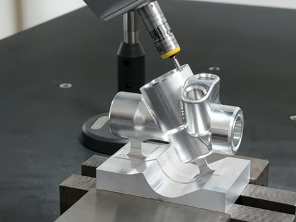
Fixed probe heads have a constant orientation and require part repositioning or special fixturing to access different faces of the part. Articulating heads can index in discrete steps (e.g. 7.5° increments) or provide continuous 2-axis motion.
Articulating systems allow the measurement of undercuts, angled holes and features on multiple sides without manual intervention. They also enable optimization of stylus length to maintain stiffness while reaching complex areas.
Optical, Laser and Vision Probes
Non-contact probes use light-based technologies to measure without touching the part. Examples include laser triangulation sensors, chromatic confocal sensors, white light sensors and video camera-based vision heads.
Applications include soft materials, small electronic components, reflective or very small features, and components requiring high-density point clouds for surface analysis. Calibration of optical probes and control of lighting conditions are essential for reliable results.
Measurement Accuracy and Performance Parameters
CMM performance is defined by recognized standards that specify test methods and permissible errors. The most widely applied standard series is ISO 10360 for CMM acceptance and reverification tests.
Key Accuracy Specifications
Important performance indicators include:
Length measurement error (E): Maximum permissible error over a range of calibrated step gauges or artifacts, often expressed as E = A + L/K (μm), where L is measured length in mm.
Probing error for size (PSize): Error associated with measuring the diameter of a calibrated sphere or ring.
Probing error for form (PForm): Deviation of measured points on a calibrated sphere from an ideal sphere fitted to those points.
Repeatability and reproducibility: Variability of measurement results under repeated conditions and between different setups.
Influence Factors on Accuracy
Accuracy is affected by multiple factors, including:
- Environmental conditions (temperature, gradients, humidity, vibration).
- Machine structure, stiffness and thermal behavior.
- Scale accuracy and compensation models.
- Probe type, stylus configuration and trigger behavior.
- Measurement strategy (probing speed, distribution of points, alignment method).
Temperature control near the reference temperature (often 20 °C) is of high importance. Many CMMs implement thermal compensation using embedded temperature sensors on scales and structures, combined with software models.
Coordinate Systems, Alignments and Datums
Correct definition of coordinate systems and datums is fundamental for meaningful inspection results. The workflow usually involves establishing a machine coordinate system, then defining a workpiece coordinate system based on part datums.
Machine, Part and Feature Coordinate Systems
The machine coordinate system (MCS) is defined by the CMM axes and origin. The part coordinate system or workpiece coordinate system (WCS) is created by measuring reference features on the part and mathematically aligning them to the drawing coordinate system.
Feature coordinate systems may also be created to simplify evaluation of features that are tilted or located in special orientations, such as hole axes or plane normals.
Datum Definition and Alignment Strategies
Datums are real features selected to establish reference planes, axes or points. Alignment typically proceeds in steps:
Translation in three directions to set the origin, rotation about axes to align orientation, and, when necessary, secondary alignments for compound datum structures.
Software provides routines for best-fit alignments, 3-2-1 alignments, and GD&T datum reference frame constructions. Correct handling of datum precedence and constraints according to standards is essential to avoid interpretation errors.
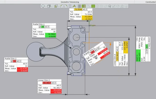
GD&T Inspection with CMMs
CMMs are widely used for evaluation of geometric dimensioning and tolerancing (GD&T) characteristics. The software connects measured features to tolerance definitions and determines conformance.
Size, Form, Orientation and Location Tolerances
Typical tolerance types evaluated on a CMM include:
- Size: diameters, widths, thickness, based on actual local or global sizes.
- Form: straightness, flatness, roundness, cylindricity.
- Orientation: parallelism, perpendicularity, angularity.
- Location: position, concentricity, symmetry.
For each tolerance, the software constructs an associated ideal feature and determines how much deviation exists within the tolerance zone. For example, flatness is calculated from the separation of two parallel planes that enclose all measured points on a surface.
Datums, Material Modifiers and Virtual Conditions
GD&T often uses modifiers such as Maximum Material Condition (MMC) and Least Material Condition (LMC), which introduce bonus tolerances dependent on feature size. Virtual condition boundaries are used for clearance and assembly checks.
CMM software requires correct interpretation of these modifiers to evaluate position and orientation tolerances at functional boundaries. Datum shift and datum mobility effects must be correctly accounted for, especially for patterns of holes and functional features.
CMM Programming and Automation
CMM programming defines the sequence of moves, probing actions, alignments and evaluations required for a part inspection process. Automation enables repeatable and efficient measurement with minimal operator intervention.
Manual Versus Offline Programming
Manual programming is performed at the machine by jogging the probe to required points and recording them. This approach is practical for simple parts and low-volume work.
Offline programming uses CAD-based software on a separate workstation. The programmer defines probe paths on the CAD model, assigns probing strategies and tolerance evaluations, and simulates the program. The program is then transferred to the CMM for execution.
CAD-Based Measurement Programming
CAD-based programming provides several advantages:
- Direct use of part geometry for feature selection and path planning.
- Automatic generation of probing points on surfaces and edges.
- Collision detection with the part, fixtures and machine components.
Association with Product Manufacturing Information (PMI), such as embedded GD&T in the CAD model, allows automatic generation of inspection plans that correspond directly to design intent.
Automation, Pallet Systems and Integration
CMMs can be integrated into automated production environments using pallet systems, robotic loading, conveyors and manufacturing execution systems (MES). Automatic workpiece identification, standardized fixturing and pre-defined measurement programs reduce manual setup time.
Measurement results can be fed back to process control systems to support closed-loop manufacturing, adjusting machining parameters based on inspection data.
Typical Applications of CMMs
CMMs are used across many industries where consistent dimensional quality is required. Their ability to measure complex 3D shapes and evaluate GD&T makes them central to quality assurance and process verification.
Automotive and Transportation Components
Automotive applications include engine components, transmission parts, gear sets, chassis structures, body-in-white assemblies and interior trim. CMMs verify dimensional conformity of critical features, such as bearing bores, sealing surfaces, mounting interfaces and safety-relevant geometry.
Aerospace and Power Generation
In aerospace and power sectors, CMMs are used for turbine blades, blisks, structural components, landing gear parts and engine housings. High-precision scanning probes are used to evaluate aerodynamic surfaces, dovetail profiles and complex freeform geometry.
Medical Devices and Precision Engineering
Medical applications include orthopedic implants, surgical instruments and dental components. Tight tolerances and complex organic shapes require CMM inspection, often with multisensor systems combining tactile and optical methods.
Precision engineering fields, such as optics housings, mechanical sensors and scientific instruments, rely on CMMs for verification of small geometries and tight fits.
Mold, Die and Tooling Inspection
Mold and die manufacturers use CMMs for verification of cavity shapes, core features, parting lines and electrode geometry. Scanning measurement allows direct comparison between the manufactured tool and the CAD model, identifying deviations for corrective polishing or machining.
Selection Criteria for a CMM
Selecting a CMM involves evaluation of technical, environmental and operational factors. The goal is to match machine capability to measurement tasks and production requirements.
Measurement Volume and Part Size
The measurement volume must be sufficient to encompass the largest parts or assemblies to be inspected, including fixtures and required probe orientations. Safety margins should be considered to accommodate future part variants and tooling.
Accuracy Requirements and Environment
Required measurement uncertainty must be clearly defined based on tolerances and quality rules. A common guideline is that the CMM expanded measurement uncertainty should not exceed a specified fraction of the tolerance, often around one-tenth.
Environmental conditions determine whether a high-precision air-conditioned metrology room is needed or whether a shop-floor CMM with enhanced robustness and compensation is appropriate.
Probing, Sensors and Part Accessibility
The complexity and accessibility of part features influence the choice of probe heads and sensors. Deep bores, undercuts and angled features may require articulating heads, long styli or special probes. Delicate surfaces or micro-features may need optical sensors or low-contact-force probes.
Software, Data Integration and Workflow
Software capabilities must support required measurement strategies, GD&T evaluation, CAD formats and data export needs. Integration with CAD/CAM, PLM, MES and SPC systems should be considered for efficient data flow.
Ease of programming and operator interface are important factors in reducing errors and training time, especially in high-mix production environments.
CMM Installation and Environmental Control
Proper installation conditions are essential for maintaining specified CMM performance. Planning includes location, foundation, temperature control and vibration isolation.
Foundations and Vibration Considerations
CMMs are sensitive to vibration from nearby machinery, forklifts, presses or external traffic. Vibration can affect probing repeatability and scanning quality. Countermeasures include isolated foundations, air-suspended platforms and appropriate placement away from vibration sources.
Large CMMs, especially gantry types, may require specialized foundations with high mass, reinforcement and leveling provisions. Installation guidelines specify allowable tilt and flatness of the support surface.
Temperature and Airflow Management
Temperature stability around the CMM is a key factor for dimensional accuracy. Recommended conditions include controlled temperature near the reference value, limited gradients across the machine, and controlled rate of change.
Airflow from air conditioning, doors or windows should be minimized in the measuring volume to avoid uneven heating or cooling. In some configurations, local enclosures or climate cabinets are used to isolate the CMM from workshop conditions.
Calibration, Verification and Traceability
CMM calibration and performance verification ensure traceability of measurements to national or international length standards. This is necessary for compliance with quality management systems and for confidence in inspection results.
Acceptance and Reverification Tests
Initial acceptance testing is based on manufacturer specifications and relevant standards. ISO 10360 defines test procedures for length measurement error, probing performance and scanning performance.
Reverification tests are conducted at regular intervals to confirm that the CMM remains within specified performance limits. They may include length measurements with calibrated artifacts and probing tests using certified spheres.
Use of Artifacts and Reference Standards
Artifacts for CMM verification include step gauges, ball plates, ring gauges, gauge blocks, reference spheres and multi-feature standards. These artifacts are calibrated by accredited laboratories, establishing traceability.
Measurement results on these artifacts are compared with nominal values to detect drifts, systematic errors or environmental influences. Corrective actions can include recalibration, compensation updates, or environmental improvements.
Operation, Measurement Strategy and Good Practices
Effective CMM operation requires appropriate measurement strategies, part fixturing and procedural discipline. Applying consistent practices minimizes variability and improves reliability.
Part Fixturing and Setup
Parts should be fixtured securely without distorting functional features. Fixturing must allow access to required surfaces while maintaining repeatable positioning. Reference stops and modular fixtures support efficient changeover between part types.
Orientation of the part relative to the CMM axes should minimize reach and stylus length while maintaining access to all relevant features.
Measurement Point Distribution and Scanning Paths
Point distribution on features influences the validity of fitted geometry. For example, measuring a plane with points evenly distributed over the surface yields more representative results than using only three points.
For scanning, strategies must consider path spacing, scanning speed, contact force and direction to capture relevant form deviations. Strategy selection may depend on expected defect patterns or critical functional areas on the part.
Uncertainty Evaluation and Documentation
Measurement uncertainty is influenced by instrument performance, environment, operator, part conditions and strategy. When required, an uncertainty budget can be established using analytical methods or simulation-based approaches.
Inspection reports should document the CMM used, calibration status, temperature conditions, measurement programs, alignments, probe configurations and any deviations from standard procedures.
Maintenance and Reliability of CMMs
Regular maintenance prolongs CMM life and helps maintain accuracy. Maintenance activities include cleaning, inspections and periodic servicing by qualified personnel.
Routine Cleaning and Checks
Guideway surfaces and air bearing pads must be kept clean to avoid contamination and wear. Dust, oil and coolant residues should be removed carefully using recommended methods. The measuring table should be kept free from chips and debris.
Operators should perform basic checks for unusual noises, air supply pressure, axis smoothness and probe triggering behavior. Any changes can indicate the need for service.
Scheduled Service and Parts Replacement
Manufacturers specify maintenance intervals for inspection of air systems, replacement of filters, verification of air bearing gaps and checks of electrical connections. Software updates and backup of controller parameters should be managed systematically.
Replacement or refurbishment of components such as bellows, cables, seals or wear elements helps maintain reliability, especially in high-utilization environments.
FAQ
What is a Coordinate Measuring Machine (CMM)?
A Coordinate Measuring Machine (CMM) is a precision measurement device used to measure the physical geometry of an object by probing discrete points on its surface in a three-dimensional coordinate system.
What are CMMs used for?
CMMs are commonly used for dimensional inspection, quality control, reverse engineering, and verification of complex parts in industries such as automotive, aerospace, medical, and precision manufacturing.
What types of Coordinate Measuring Machines are available?
The main types include bridge CMMs, gantry CMMs, cantilever CMMs, horizontal arm CMMs, and portable CMMs, each designed for different part sizes and measurement environments.
Can a CMM be used for reverse engineering?
Yes. CMMs can collect precise point cloud data that can be used to create or validate CAD models for reverse engineering applications.
How accurate is a CMM?
CMM accuracy depends on the machine type, environment, probe system, and calibration, but modern CMMs can achieve accuracy in the micron or sub-micron range.
