
Manifold blocks are central connection and distribution components in hydraulic and pneumatic systems. They combine multiple ports, valves and passageways into a single compact unit to direct, control and monitor fluid flow. Proper selection of manifold block type has a direct impact on system performance, reliability, footprint and serviceability.
Fundamentals of Manifold Blocks
Manifold blocks are solid bodies (typically metal) containing internal channels that connect ports, valves and instruments. The geometry of these channels defines the flow path, pressure distribution and functional behavior of the circuit.
Key characteristics include:
- Flow path type: parallel, series, distribution or combined
- Medium: oil (hydraulic), air (pneumatic), water or other compatible fluids
- Porting: size, type, orientation and number of ports
- Integration level: simple distribution block or complex valve manifold
In design and application, manifold blocks reduce external piping, minimize leakage points, simplify assembly and allow more precise control of flow and pressure.
Major Manifold Block Type Categories
Manifold block types can be categorized by their primary functional layout. Understanding these categories helps when mapping application requirements to the appropriate manifold configuration.
Parallel Flow Manifold Blocks
Parallel flow manifolds distribute a common inlet to multiple outlets that operate independently. Each outlet usually sees nearly the same supply pressure, subject to local flow losses.
Typical characteristics:
- One or more common inlet ports feeding multiple branch ports
- Minimal interaction between branches under moderate flow conditions
- Used where identical or similar functions are replicated (e.g., multiple actuators)
Series Flow Manifold Blocks
Series flow manifolds route fluid from one function to the next in a defined order. The outlet of one internal passage becomes the inlet to the next.
Key characteristics:
They are used when a cascade of functions is needed, such as pressure reduction followed by flow control, or sequential actuation that depends on upstream conditions. Careful pressure and flow analysis is required because upstream conditions affect downstream performance.
Distribution and Collection Manifold Blocks
Distribution manifolds split fluid from one or more inlets to multiple outlets, while collection manifolds combine multiple inlets into one or a few outlets. Many blocks implement both functions simultaneously.
These are common in centralized supply and return systems, lubrication systems, heating and cooling circuits, and central pneumatic supply lines.
Valve Manifold Blocks
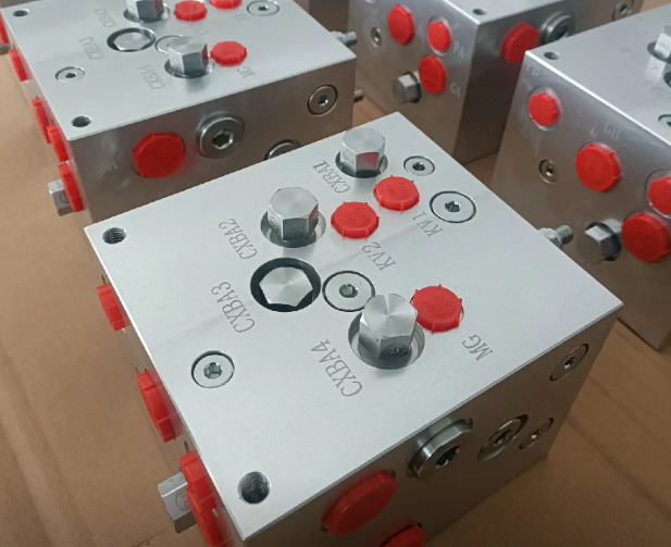
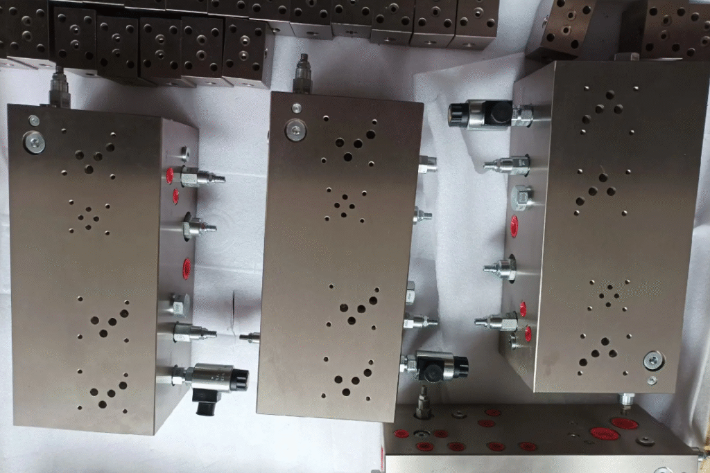
Valve manifolds integrate two or more valves into a single block. They may contain directional control valves, pressure control valves, flow control valves, or a combination.
Benefits include reduced leak paths, compact installation and improved maintenance access. Valve manifolds can be configured as subplate-mounted, sandwich-stacked, modular or custom integrated blocks, depending on the valve technology used.
Subplate and Sandwich Manifold Blocks
Subplate manifold blocks serve as mounting bases for standardized valves, following interface standards such as ISO or CETOP. Sandwich (stack) blocks are stacked between valve and subplate to add functions.
Subplates provide standardized porting and flow passages beneath the valves, while sandwich blocks add modular functions like check valves, pressure reducing valves, or flow control for specific ports within the valve’s A, B, P, or T lines.
Modular Manifold Blocks
Modular manifolds consist of individual blocks that are assembled together to build up a system. Each module implements a specific function (e.g., isolation, regulation, distribution) and interconnects through standardized faces or tie rods.
This approach enables flexible system expansion, easy reconfiguration and replacement without redesigning the entire manifold structure.
Custom and Integrated Manifold Blocks
Custom manifolds are engineered for a specific machine or process, integrating multiple valves, sensors and auxiliary devices into a single block tailored to the application.
These blocks consolidate a large portion of the hydraulic or pneumatic circuit, reducing external hoses and fittings. They often combine parallel, series and distribution features within one structure, guided by the circuit’s schematic.
Hydraulic Manifold Blocks
Hydraulic manifold blocks are designed for liquid media (typically mineral oil or synthetic hydraulic fluids) under high pressure and varying flow conditions.
Typical Hydraulic Manifold Functions
Hydraulic manifolds can integrate many control and safety elements:
- Directional control functions for cylinders and motors
- Pressure control, such as relief, reducing and sequence valves
- Flow control, such as throttle valves and flow dividers
- Check and counterbalance functions for load holding
- Safety functions like overpressure protection and emergency shutoff
Hydraulic Manifold Block Types by Circuit Layout
Common layout-oriented types include:
Directional valve manifolds: These blocks mount several directional control valves to actuate multiple cylinders or motors from a single pressure supply. Internal galleries distribute pressure and return lines while connecting individual work ports.
Load-sensing manifolds route load-sensing signals and supply pressure to load-sensing pumps and valves, maintaining energy-efficient operation.
Proportional valve manifolds combine proportional valves with integrated passages that minimize dead volume and pressure loss, supporting precise flow and pressure control.
Hydraulic Pressure and Flow Parameters
The design and selection of hydraulic manifold blocks must reflect operating pressure, peak pressure, fluid viscosity, and expected flow ranges. Typical industrial hydraulic systems operate between 140–350 bar, with some high-pressure systems exceeding 400 bar. Flow capability depends on port size, internal passage diameter and overall layout.
| Application Category | Pressure Range (bar) | Flow Range (L/min) | Typical Port Sizes |
|---|---|---|---|
| Industrial machinery | 140–250 | 10–150 | G 1/4 to G 3/4, SAE 6–16 |
| Mobile equipment | 180–350 | 20–300 | SAE 8–24, flange ports |
| High-pressure tools | 350–700 | 1–50 | Small UNF, cone fittings |
| Low-pressure hydraulics | 20–80 | 5–200 | G 1/4 to G 1 |
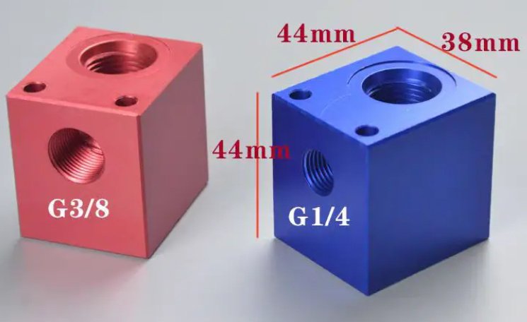
Hydraulic Manifold Porting Types
Typical hydraulic manifold ports include:
BSPP (G) parallel threads: Common in European systems; sealed with bonded seals or O-ring face seals. NPT/NPTF tapered threads: More common in some regions; rely on thread interference and sealing compounds. SAE straight threads with O-ring (ORB): Provide reliable high-pressure sealing with minimal risk of thread leakage. Cartridge valve cavities follow standards such as ISO 7789 or manufacturer-specific geometries.
Hydraulic Manifold Materials and Surface Treatment
Hydraulic manifolds use materials with sufficient strength and fatigue resistance under internal pressure:
Carbon steels are widely used for high-pressure systems due to strength and availability. Aluminum alloys reduce weight and are suited for moderate pressures and mobile equipment. Stainless steels are selected when corrosion resistance or specific fluid compatibility is required.
Surface treatments may include anodizing (for aluminum), zinc plating, nickel plating, or painting to limit corrosion and improve cleanliness.
Pneumatic Manifold Blocks
Pneumatic manifold blocks carry compressed air, usually at significantly lower pressures than hydraulic systems, but with higher flow velocities and different sealing requirements.
Pneumatic Manifold Functions
Pneumatic manifolds distribute air to cylinders, rotary actuators, air tools and other downstream components. They often incorporate control valves, flow regulators, and quick exhaust functions.
Common functions include:
Supplying multiple valves from a central compressed air source; Integrating on/off isolation for specific sections; Providing common exhaust and silencing for multiple outlets; Hosting electrical or fieldbus interfaces for valve control modules.
Pneumatic Valve Manifold Types
Pneumatic valve manifolds typically arrange multiple solenoid valves on a common base block. The base contains internal supply and exhaust galleries, plus individual work ports per valve station.
Manifold types include compact inline bases with side ports, stackable fieldbus manifolds with integrated electronics, and distribution manifolds that only route air without integrated valves.
Pneumatic Pressure and Flow Parameters
Pneumatic systems typically operate between 4–10 bar. Flow capability is often specified as nominal flow rate at a given pressure drop and inlet pressure. Internal passages and port sizes must limit pressure drop to keep actuators responsive.
| System Type | Operating Pressure (bar) | Nominal Flow (L/min) | Typical Port Sizes |
|---|---|---|---|
| General industrial automation | 5–8 | 200–1500 | G 1/8 to G 1/2 |
| High-flow actuation | 6–10 | 1000–5000 | G 3/8 to G 3/4 |
| Precision low-flow control | 3–7 | 10–300 | M5, G 1/8 |
| Compact valve terminal systems | 4–8 | 50–1000 | M5, G 1/8, push-in fittings |
Pneumatic Materials and Construction
Pneumatic manifolds often use aluminum, brass or high-performance polymers. Aluminum offers good machinability and weight savings, while brass provides durability and corrosion resistance in humid or aggressive environments. Polymers are used in compact valve terminals and modular manifolds where fluid compatibility and mechanical loads allow.
Distribution and Header Manifold Blocks
Distribution or header manifolds are simple blocks that split or combine flow, usually without integrated control valves. They are used in lubrication, coolant, heating and cooling, chemical dosing, and some pneumatic networks.
Single-Sided and Double-Sided Distribution Blocks
Single-sided manifolds have all branch ports on one face, simplifying installation in confined spaces. Double-sided manifolds place ports on opposing faces, helping to minimize tubing crossing and enabling symmetric connections.
Isolated vs Common Return Manifolds
In some applications, each branch needs an isolated return line, while in others a common return is sufficient. Distribution manifolds can be configured with separate channels or a shared gallery, depending on how contamination, backflow and pressure interactions must be controlled.
Subplate and Sandwich Manifold Systems
Subplate and sandwich systems are widely used in standardized hydraulic valve assemblies and in some pneumatic installations.
Subplate Manifold Types
Subplates provide standardized mounting surfaces for directional control valves and other components. Types include single-station subplates for individual valves, multi-station manifolds that connect several valves to a shared pressure and return gallery, and through-port subplates that permit continuation of supply and return lines along a row of valves.
Sandwich (Stack) Block Types
Sandwich blocks are installed between the valve and the subplate to add specific functions. Examples are pressure relief modules in the P-line, flow controls in the A and B lines, and check valves enabling meter-in or meter-out control. These blocks rely on standardized porting patterns and sealing arrangements to ensure internal separation of functions.
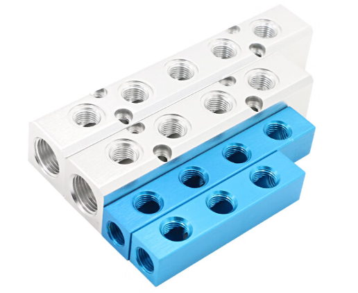
Modular and Stackable Manifold Blocks
Modular systems use multiple blocks joined together mechanically and hydraulically to form a complete manifold assembly. Each module performs a specific role and interfaces with neighbors through matching port faces.
Linear and Matrix Modular Arrangements
Blocks can be arranged linearly, where supply and return galleries traverse all modules, or in matrix layouts to accommodate more complex circuit structures. Tie rods, bolts or clamp frames provide structural integrity while seals maintain gallery continuity.
Advantages of Modular Manifolds
Modular manifolds allow progressive expansion as new actuators or functions are added, reduce engineering time for small changes, and simplify logistics by using standard modules. They also simplify maintenance because individual modules can be removed and replaced without disturbing the entire manifold.
Custom Integrated Manifold Blocks
Custom integrated manifolds consolidate large portions of a circuit into a single block or a small set of blocks. They are often used in high-volume machines or where envelope constraints demand tightly packaged solutions.
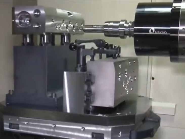
Design Considerations for Custom Blocks
Designers must translate the schematic into 3D passageways while respecting drilling capabilities, minimum wall thicknesses, and machining access. Flow simulation, pressure drop analysis and cavitation checks are used to validate internal geometry.
Channels must avoid sharp turns, sudden contractions, and intersecting drillings that compromise strength or cause turbulence. The design also needs to consider assembly and service access for valves, sensors, plugs and test points.
Integration of Sensors and Accessories
Custom manifolds can integrate pressure sensors, temperature probes, flow meters and diagnostic ports. This integration supports condition monitoring and simplifies commissioning by centralizing measurement points. However, each additional device requires its own porting, sealing and mechanical support within the block.
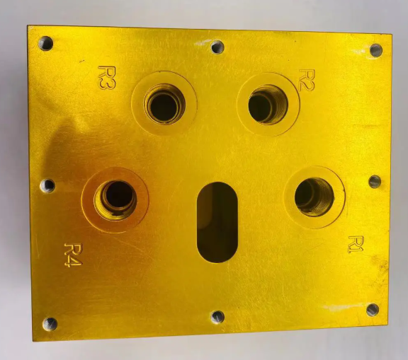
Port Configuration and Connection Types
Port configuration is critical for correct installation, accessibility and fluid performance. Port type, size, orientation and labeling must match application needs and regional standards.
Threaded Ports
Threaded ports are common for both hydraulic and pneumatic manifolds. Main categories:
BSPP (G) ports use parallel threads. Sealing is achieved via bonded washers or O-ring face seals. NPT/NPTF ports use tapered threads and require thread sealant. SAE J1926 straight-thread O-ring ports provide reliable high-pressure sealing with reduced risk of thread-related leaks.
Cartridge Valve Cavities
Cartridge valve manifolds contain cavities following specific standards (e.g., ISO, CETOP or proprietary). Each cavity shape and depth is matched to a particular valve family. These cavities allow insertion of screw-in valves for pressure control, flow control, check functions and more.
Flange and Face Ports
In high-flow or high-pressure applications, flanged or face-ported connections reduce stress on threads and improve flow characteristics. These interfaces use bolts and O-ring seals or gaskets for sealing and mechanical retention.
Material Selection for Manifold Blocks
Material selection is determined by pressure rating, environmental conditions, fluid type, weight constraints and cost targets.
Common Manifold Materials
Carbon steel offers high strength and good fatigue resistance, suitable for heavy-duty hydraulic manifolds. Stainless steel provides corrosion resistance for aggressive media or outdoor installations. Aluminum is used where weight reduction is critical or where pressure levels are moderate. Brass is common in compressed air, water and some chemical applications, combining good machinability with corrosion resistance.
Mechanical and Chemical Considerations
Yield strength, tensile strength and fatigue limits must exceed calculated stresses under peak pressure and dynamic loading. Corrosion behavior must be compatible with the fluid, ambient atmosphere and cleaning agents. For some applications, regulatory requirements (e.g., for food, pharmaceutical or marine use) may dictate material choice.
Design Considerations for Manifold Block Types
Proper design ensures that the selected manifold block type operates reliably and meets performance targets. Several technical aspects need careful attention.
Flow Path and Pressure Drop
Internal channels must provide adequate cross-sectional area to limit pressure drop at maximum flow. Long or sharply bent passages increase losses and can cause uneven distribution among branches. Designers often aim for uniform flow conditions across parallel stations to maintain consistent actuator performance.
Strength and Fatigue
Wall thickness between adjacent channels, and between channels and the outer surface, must be sufficient to withstand internal pressure with a suitable safety factor. Repeated pressure cycling can lead to fatigue, so stress concentrations at cross drillings and corners must be minimized.
Leak Tightness and Sealing
Manifold design must ensure proper sealing at all interfaces: threaded ports, cartridge cavities, valve mounting faces and inter-module joints. O-ring groove dimensions, surface finish and compression must match specification data for the selected seals.
Cleanliness and Contamination Control
Dead-end pockets, blind drillings and stagnant zones can trap contaminants. Whenever possible, flow paths should be self-flushing and easy to clean during manufacturing and maintenance. Provision for flushing ports or filter integration enhances long-term reliability.
Application-Specific Manifold Types
Different industries use manifold blocks in characteristic ways, often combining several of the previously described types.
Mobile Hydraulic Manifolds
Mobile equipment uses compact, robust manifolds that integrate multiple control functions for cylinders, steering and auxiliary circuits. Weight, envelope size and environmental sealing are important factors, and aluminum or high-strength steels are common materials.
Industrial Automation Manifolds
Industrial automation systems use pneumatic and hydraulic manifolds to actuate handling systems, presses, clamping fixtures and robotics. Valve manifolds with electrical or fieldbus interfaces are common, as they centralize control while simplifying wiring and air routing.
Process and Fluid Handling Manifolds
Distribution manifolds are widely used in process industries to route liquids and gases to multiple circuits or measurement points. Stainless steel manifolds are common when fluid purity and corrosion resistance are critical.
Selection Guidelines for Manifold Block Types
Selecting the right manifold type requires understanding the circuit, the medium, and the operating conditions. The choice is rarely based on one parameter; it involves balancing several criteria.
Matching Type to Circuit Function
Parallel manifolds suit multiple identical or similar actuators operating independently. Series manifolds are appropriate when a strict sequence of functions is needed. Valve manifolds should be selected when multiple valves share a common supply and return. Modular or custom manifolds are preferred when future expansion or dense integration is expected.
Sizing by Flow and Pressure
Port size and internal passage dimensions must be matched to maximum continuous and peak flow rates. Pressure rating must exceed the maximum expected system pressure plus a safety margin. Manufacturers typically provide pressure and flow ratings for each manifold type; these must be cross-checked with system requirements.
Environmental and Medium Constraints
Temperature extremes, exposure to moisture, chemicals, vibration and mechanical shock influence material and layout decisions. For example, outdoor systems may require stainless steel or coated manifolds, and low-temperature environments may require consideration of seal materials and thermal expansion.
Installation and Maintenance Considerations
Access to mounting bolts, valve interfaces, test ports and plugs must be considered at the design stage. Manifolds should be oriented to allow clean hose routing and to avoid air entrapment or unintended siphoning. Serviceability improves when functionally related valves and components are grouped logically on the block.
FAQ: Manifold Block Types
What are the main types of manifold blocks?
Manifold blocks are commonly classified into hydraulic manifold blocks, pneumatic manifold blocks, valve manifold blocks, and custom CNC-machined manifold blocks. Each type is designed for specific fluid, pressure, and system requirements.
What is the difference between hydraulic and pneumatic manifold blocks?
Hydraulic manifold blocks are designed to handle high-pressure liquid systems, while pneumatic manifold blocks are used for compressed air applications with lower pressure. The internal flow paths, materials, and sealing methods differ accordingly.
Can hydraulic and pneumatic manifolds use the same block design?
Hydraulic and pneumatic manifolds follow similar design principles, but they are not interchangeable. Hydraulic manifolds must withstand much higher pressures and usually require materials and wall thickness suited for those loads. Pneumatic manifolds operate at lower pressure but must handle higher flow velocities and different sealing behavior with compressible air. Port types, internal geometries and materials are therefore selected specifically for each medium.
When should I choose a custom manifold block instead of a standard one?
Custom manifold blocks are recommended when standard designs cannot meet your flow path, port configuration, size, or performance requirements. Custom designs can reduce leakage points, improve efficiency, and simplify system assembly.
