
What Is a Manifold Block
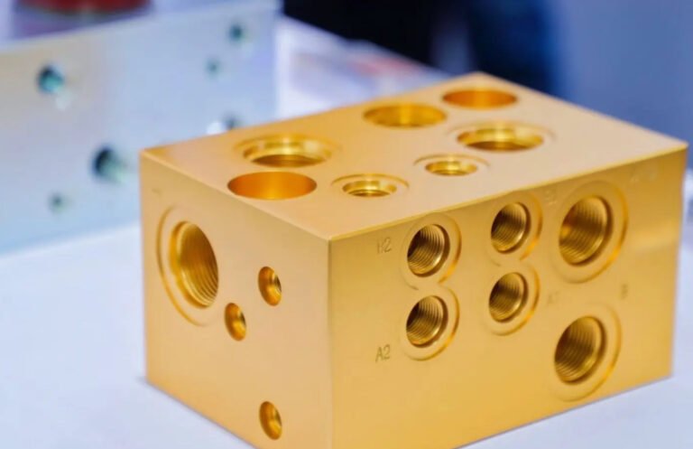
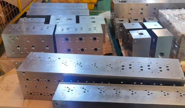
A manifold block is a solid metal (or polymer) body that routes and distributes fluids or gases between multiple ports, valves, and actuators. It integrates passages that replace complex external piping, allowing control and monitoring of pressure, flow, and direction inside a compact unit.
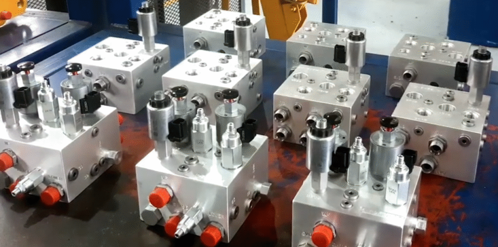
Manifold blocks are used in hydraulic, pneumatic, and process control systems to connect pumps, compressors, valves, actuators, gauges, and sensors. They can be simple distribution blocks or highly integrated assemblies incorporating logic, pressure control, and safety functions.
Key Functions and Applications
The primary functions of a manifold block include:
- Distributing flow from a single supply to multiple circuits or consumers
- Combining flows from several circuits into a common return line
- Providing a mounting and interconnection base for valves and sensors
- Enabling isolation, venting, pressure measurement, and safety interlocks
Typical applications include:
- Industrial hydraulic power units and actuator control (presses, injection molding, machine tools)
- Mobile hydraulics (construction equipment, agricultural machinery, lifting platforms)
- Pneumatic automation (manifold-mounted solenoid valves, air preparation units)
- Process instrumentation (manifolds for pressure, differential pressure, and flow transmitters)
- Gas distribution panels and test stands (inert gases, instrument air, specialty gases)
Common Types of Manifold Blocks
Manifolds can be categorized by function, mounting method, and fluid type. Selecting the appropriate type is fundamental for safe and efficient system operation.
| Type | Description | Typical Uses |
|---|---|---|
| Hydraulic valve manifold block | Block with internal passages and cavities for hydraulic valves and controls | Industrial and mobile hydraulic systems, power units |
| Pneumatic valve manifold | Base manifold for multiple solenoid valves with common supply and exhaust | Automation lines, robotics, packaging, assembly |
| Instrument/manifold valve block | Multi-valve block for pressure and differential pressure transmitters | Process industries (oil & gas, chemical, power), measurement taps |
| Distribution block | Simple block that splits one inlet into several outlets | Lubrication systems, coolant distribution, auxiliary circuits |
| Subplate / sandwich manifold | Plate-based manifold for stackable CETOP/NG valves | Modular hydraulic stations, configurable systems |
| Custom integrated manifold | Application-specific block incorporating multiple hydraulic or pneumatic functions | Compact machinery, OEM solutions, high-performance systems |
Materials and Surface Treatments
Material selection affects strength, corrosion resistance, weight, machinability, and compatibility with the working fluid.
Common Manifold Materials
- Carbon steel: High strength, suitable for high-pressure hydraulics, typically requires surface protection against corrosion.
- Stainless steel: Excellent corrosion resistance, used in aggressive environments, chemical and offshore applications.
- Aluminum alloys: Lightweight and easy to machine, widely used for medium-pressure hydraulics and pneumatics.
- Brass: Good corrosion resistance and machinability, common in instrument and low-pressure gas manifolds.
- Engineered plastics: Used for low-pressure pneumatic or chemical applications where weight and corrosion resistance are critical.
Typical Surface Treatments
For carbon steel and sometimes aluminum manifolds, surface treatments improve durability:
Zinc plating, nickel plating, anodizing, and phosphate coatings are applied depending on environmental conditions. Internal surfaces are often left untreated or treated carefully to avoid flaking that could contaminate the fluid system.
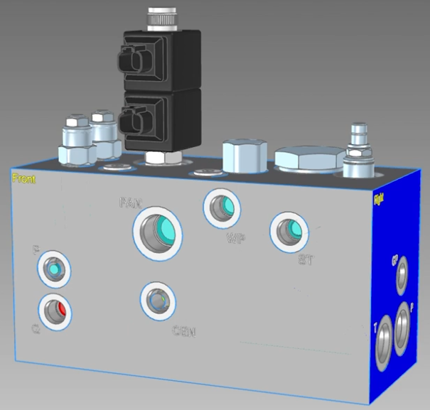
Port Standards and Connection Interfaces
Manifold ports must match the piping or hose connections and follow recognized standards. Incorrect selection can lead to leakage, poor sealing, or assembly failures.
Threaded Port Standards
Common port thread types include:
- ISO 1179 / DIN 3852 (BSPP) ports for hydraulic and general industrial use
- ISO 6149 metric ports designed for high-pressure hydraulics
- SAE J514 (UN/UNF threads) and SAE J1926 O-ring boss ports in North American systems
- NPT/NPTF tapered threads for certain pneumatic and process applications
Each thread standard has specific requirements for tap drill size, thread engagement, and sealing method (metal-to-metal, O-ring, or thread sealant). Mixing incompatible thread types is not permissible.
Valve Interface Standards
Hydraulic valve manifolds often follow mounting interface standards such as:
CETOP/NG (ISO 4401), ISO 7789, and other cartridge valve cavity standards (e.g., ISO 17209 for screw-in cartridges). Pneumatic valve manifolds commonly use manufacturer-specific base patterns with common supply and exhaust channels.
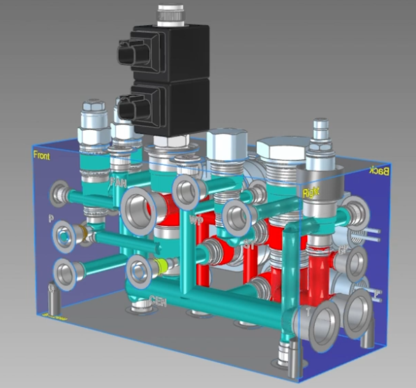
Flow Paths, Cavities, and Internal Geometry
The internal geometry of a manifold block determines pressure drop, response time, and noise level. It is designed using drilled passages, cross-drillings, cavities, and sometimes milled channels.
Flow Path Design Considerations
Key parameters include:
Flow rate, allowable pressure drop, flow velocity, and direction changes. Excessive velocity or sharp turns can increase pressure loss, generate heat, and cause erosion. Gradual changes in cross-section and minimal 90-degree turns are preferred.
Where multiple circuits interact, internal cross-communication must be controlled to avoid unintended pressure feedback or hydraulic lock.
Valve Cavities and Cross-Drilling
Cartridge valve manifolds use cavities with well-defined diameters, depths, and shoulder surfaces for O-ring sealing. The cavity design must respect manufacturer specifications to ensure correct valve installation and sealing.
Cross-drilling is used to connect intersecting passages. These cross-holes are often sealed with threaded plugs or pressed-in plugs. Plug selection, thread engagement, and sealing must consider pressure rating and temperature range.
Sizing and Pressure Rating
Correct sizing ensures the manifold can withstand operating pressures, flows, and mechanical loads. Sizing covers both mechanical strength and hydraulic or pneumatic performance.
Pressure Rating and Safety Factors
Manifolds are generally rated with:
Maximum working pressure, test pressure (often 1.3 to 1.5 times the working pressure), and burst pressure. Design codes or company standards define the required safety factor between working and failure pressure. Material yield strength, minimum wall thickness, and stress concentrations from drilling are part of the calculation.
Port Size and Flow Capacity
Port size is determined by permissible pressure drop and flow velocity. For hydraulic oil, typical nominal flow velocities in lines are limited to values that balance pressure loss and system responsiveness. For compressed air, higher velocities are acceptable, but noise and pressure drop must still be considered.
Flow calculations use formulas or manufacturer charts. The internal diameter of drilled passages should be consistent with or slightly larger than the nominal port size to avoid bottlenecks.
Sealing Concepts and Leakage Control
Sealing is critical for safety and system efficiency. Manifolds employ multiple sealing methods simultaneously, including between manifold and valves, plugs, and external connections.
Static Seals in Manifold Blocks
Common static seal types include:
O-rings in grooves, metal-to-metal cone seats, gasketed interfaces, and bonded seals (washers with elastomer sealing lips). Groove dimensions, surface finish, and compression are defined according to O-ring standards. Manifold surfaces in contact with seals must have appropriate roughness and flatness.
Leakage Considerations
Potential leakage points are:
Port threads, plug threads, valve mounting interfaces, and micro-porosity in cast blocks. Proper torque, correct seal material, and use of compatible thread sealants are necessary. Pressure testing after assembly (e.g., hydrostatic or pneumatic test) is used to confirm leakage performance.
Design Considerations and Layout Practice
Efficient manifold design organizes functions logically and simplifies installation and maintenance. Design tasks typically include function grouping, drilling layout, strength analysis, and manufacturing feasibility assessment.
Functional Grouping and Circuit Logic
Valves and ports are grouped logically according to circuit diagrams. Examples include grouping directional valves for multiple actuators, placing pressure relief valves close to pump ports, and arranging test points in accessible positions. Reducing the length of high-flow paths helps minimize pressure loss.
Mechanical Layout
Mechanical layout must consider:
Minimum wall thickness between passages and outer surfaces, distance between adjacent drillings, mounting hole positions, and access for tooling during manufacturing. Avoiding intersecting drillings at weak angles and preventing thin webs of material between high-pressure passages reduces the risk of cracking.
Thermal and Environmental Considerations
High operating temperatures affect material strength and seal elasticity. The design should provide sufficient thermal mass or cooling where required and account for expansion effects. In outdoor or corrosive environments, material and surface protection are selected to prevent external corrosion and thread seizure.
Manifold Selection Guide
Selecting a manifold block for a specific application requires matching technical requirements to available products or custom designs.
| Parameter | Description | Selection Considerations |
|---|---|---|
| Working fluid/gas | Hydraulic oil, water-glycol, compressed air, process gas, etc. | Chemical compatibility, viscosity, lubricity, cleanliness requirements |
| Operating pressure | Normal and maximum system pressure | Material strength, wall thickness, port and plug rating |
| Flow rate | Maximum continuous and peak flow | Port size, passage diameter, pressure drop limits |
| Number of circuits | Count of actuators, measurement points, or branches | Required number of stations, ports, valve positions |
| Valve type and standard | Directional, pressure, flow control, solenoid, cartridge, etc. | Interface standard, cavity type, required options and accessories |
| Environment | Indoor, outdoor, offshore, corrosive, cleanroom | Material, surface treatment, enclosure, IP rating of valves |
| Mounting and footprint | Available space and mounting surfaces | Orientation, access for wiring and piping, weight limits |
| Maintenance concept | Planned service intervals and access needs | Requirement for isolation valves, test ports, bypass lines |
Installation and Mounting Practices
Correct installation avoids stress, leakage, and premature failure. Mounting method, orientation, and support must be coordinated with system design.
Mounting Orientation and Support
Manifolds may be mounted on machine frames, panels, or brackets. The support must carry the combined weight of the manifold, valves, and connected piping without distortion. Avoid mounting configurations that transfer pipe forces into the manifold ports.
Piping and Hose Connections
Key aspects include:
Using compatible fittings and threads, observing recommended tightening torques, supporting hoses and tubes to reduce vibration, and allowing for thermal expansion. For high-pressure systems, rigid tubes with suitable supports are often preferred near the manifold.
Electrical and Signal Routing
For pneumatic or hydraulic manifold block with solenoid valves or sensors, cable routing should avoid sharp bends, abrasion, and high-temperature areas. Connectors must maintain ingress protection rating, and grounding or bonding should follow local electrical standards.
Commissioning and Testing
After installation, commissioning verifies functional performance and leakage integrity before placing the system into regular operation.
Pressure and Leakage Tests
Common tests include hydrostatic pressure testing with liquid at specified test pressure, pneumatic tests where appropriate, and visual inspection for external leaks at all joints. Valves are actuated during tests to ensure sealing in different switching positions.
Functional Verification
Functional testing confirms correct operation of all circuits. Steps include verifying valve response, actuator motion, pressure control behavior, and sensor readings. Flow or pressure anomalies often indicate internal restrictions, incorrect connections, or contamination.
Operation and System Integration
During operation, the manifold block becomes part of a larger fluid power or process control system. Interaction with other components must be understood for safe and reliable functioning.
Pressure and Flow Interaction
Shared supply and return paths in a manifold can cause interaction between circuits. For example, operation of one actuator may influence pressure available to another. The design and control strategy should account for this, using separate sections or pressure compensation where required.
Monitoring and Diagnostics
Integrating pressure gauges, transmitters, temperature sensors, and flow meters on or near the manifold facilitates diagnostics. Test ports and diagnostic couplings allow connection of portable measuring devices without disturbing the piping.
Maintenance, Inspection, and Service
Regular maintenance keeps the manifold and associated system within design performance limits. Maintenance activities focus on cleanliness, sealing integrity, and mechanical condition.
Routine Inspection
Routine checks include observing for external leaks, corrosion, loose fittings, unusual noise, and vibration. Valves mounted on the manifold should be inspected for electrical connection integrity, coil condition, and response time.
Cleaning and Contamination Control
Contamination can cause valve sticking, erosion, and premature wear. For hydraulic manifolds, system cleanliness follows defined fluid cleanliness classes. Filters and strainers should be maintained, and any disassembly work must follow strict cleanliness procedures. Pneumatic manifolds benefit from proper filtration and water separation upstream.
Seal and Component Replacement
O-rings, gaskets, and plugs may require replacement during scheduled service. Replacement procedures rely on correct identification of seal material, dimensions, and torque values. Valves can often be replaced individually without removing the manifold, provided isolation is possible.
Safety Considerations
Manifolds operate under pressure and sometimes high temperature. Safe design and operation practices reduce the risk of injury or system damage.
Pressure-Related Safety
Relief valves must be installed and set correctly to protect the manifold and connected equipment from overpressure. Before maintenance, circuits must be isolated and depressurized. Lockout/tagout procedures help prevent accidental activation.
Mechanical and Environmental Safety
Manifolds and attached components must be shielded where there is a risk of impact or exposure to hot surfaces. In environments with flammable fluids or gases, suitable material selection, bonding, and grounding reduce ignition risk. Noise from high-velocity flows should be mitigated where required.
Typical Issues and Considerations in Practice
In practical use, several issues may arise which can be mitigated through proper design and operation.
Pressure Drop and Response Time
Excessive pressure drop can reduce actuator force and slow response. This often results from undersized passages, long internal flow paths, or contamination buildup. Designing for adequate flow cross-sections and maintaining cleanliness helps preserve system performance.
Thermal Effects
Continuous operation at high flow and pressure generates heat in the manifold. Temperature rise can influence viscosity of hydraulic fluids and the elasticity of seals. Adequate cooling and fluid conditioning help maintain stable operating conditions.
Modification and Expansion
Adding new circuits or valves to an existing manifold is limited by available ports, internal passages, and mechanical strength. When future expansion is expected, it is advisable to include spare stations, blanked ports, or modular extension capability in the original design.
FAQ About Manifold Blocks
What is a manifold block?
A manifold block is a solid block with internal flow passages designed to connect and control multiple hydraulic or pneumatic valves within a compact system.
What are manifold blocks used for?
Manifold blocks are used to simplify hydraulic circuits, reduce external piping, minimize leakage points, and improve system efficiency and reliability.
What types of valves can be mounted on manifold blocks?
Directional control valves, pressure relief valves, flow control valves, check valves, proportional valves, and cartridge valves can all be mounted on manifold blocks.
What industries commonly use manifold blocks?
Manifold blocks are widely used in industries such as industrial automation, construction machinery, agriculture, energy, and mobile hydraulics.
