
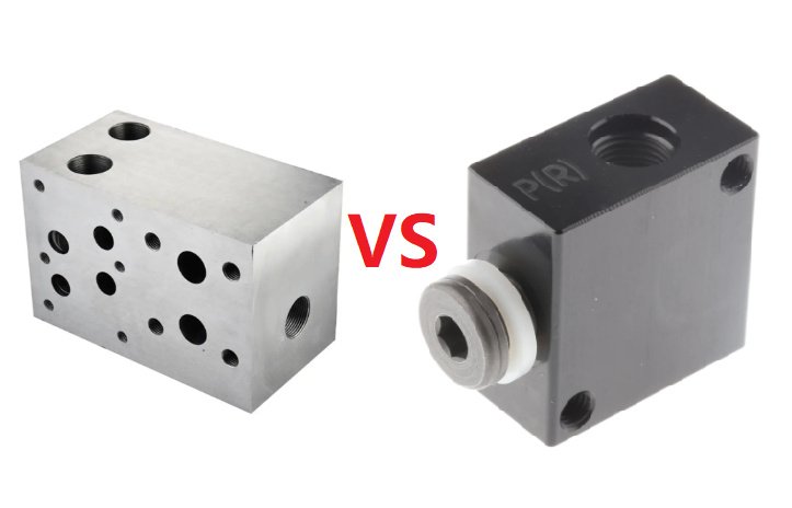
In fluid power and process control systems, the terms manifold block and valve manifold are often used together but they do not describe exactly the same component. Understanding their differences, overlaps, and correct use is important for hydraulic systems, pneumatic circuits, and instrumentation installations.
Definitions and Core Concepts
Although both deal with distributing and controlling fluids or gases, a manifold block and a valve manifold have distinct emphases in design and function.
Manifold Block: Core Definition
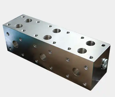
A manifold block is a solid body containing internal passages that distribute, combine, or redirect fluid or gas between multiple ports or circuits. The primary role is fluid distribution and circuit integration; valves may be mounted to it, but the block itself is mainly a flow channel and interconnection platform.
Typical features of a manifold block include:
- Solid metal block (or modular plates) with drilled and machined internal passages
- Multiple ports arranged for compact piping or tubing connections
- Interface surfaces and mounting patterns for cartridge valves, subplate-mounted valves, or fittings
- Integrated galleries for pressure, return, and service lines in hydraulic or pneumatic systems
Valve Manifold: Core Definition
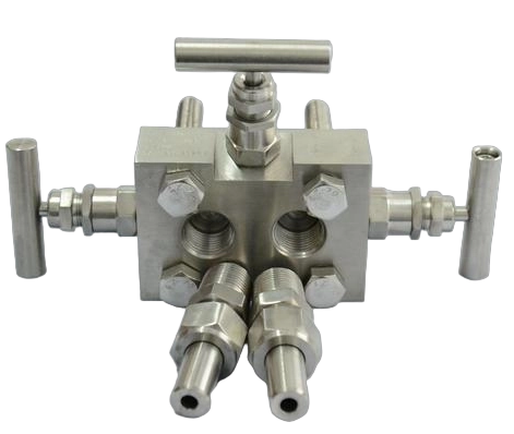
A valve manifold is an assembly consisting of multiple valves integrated into a single manifold body or base. Its primary role is functional control of fluid or gas through configuration of several valves together, often for measurement, isolation, equalization, or directional control.
Typical features of a valve manifold include:
- Multiple valves within one compact assembly (2-valve, 3-valve, 5-valve, or multi-station)
- Standardized patterns for process instruments or actuators (such as pressure transmitters or solenoid valves)
- Dedicated functions such as isolation, venting, equalizing, or switching between ports
- Reduction of external piping by integrating valve functions in one assembly
Conceptual Difference in Focus
In simple terms, a manifold block is primarily a distribution and connection component, while a valve manifold is primarily a functional control unit integrating several valves. In practice, many assemblies combine both roles.
Types of Manifold Blocks
Manifold blocks appear in multiple technical contexts. Their design, pressure rating, and interfaces vary by application.
Hydraulic Manifold Blocks
Hydraulic manifold blocks are used in high-pressure hydraulic systems to route oil between pumps, actuators, accumulators, and auxiliary circuits. They integrate multiple functions into a compact, rigid module.
Common characteristics include:
- Materials: typically carbon steel, ductile iron, or stainless steel for corrosive environments
- Pressure ratings: from 140 bar (2000 psi) up to 420 bar (6000 psi) or higher, depending on design and standard
- Valve mounting: cartridge cavities (ISO, CETOP, or proprietary) or subplate mounting according to ISO 4401
- Internal channels: drilled galleries for pump line, tank line, control lines, and service ports
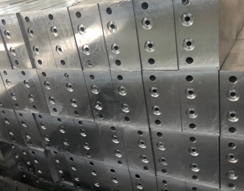
Hydraulic manifold blocks can be:
Mono-block manifolds: single solid block with fully integrated circuits, optimized for robustness and size but less flexible for later modifications.
Modular stack manifolds: multiple plates stacked together, each plate containing specific circuit functions, offering easier reconfiguration in the field.
Pneumatic Manifold Blocks
Pneumatic manifold blocks distribute compressed air to multiple actuators or valve stations with lower pressure compared to hydraulics but usually higher flow rates in relation to port size.
Typical parameters:
- Materials: aluminum alloys, brass, stainless steel, or engineering plastic for low-pressure distribution
- Pressure range: typically 0–10 bar (0–145 psi), sometimes slightly higher for industrial compressed air networks
- Port standards: BSPP, NPT, or metric threads; quick-connect fittings in many factory installations
- Mounting style: panel, DIN rail, or machine frame mounting for compact valve-island systems
Process and Instrumentation Manifold Blocks
In process industries, some manufacturers use the term manifold block for distribution blocks feeding multiple instruments or sample lines. These are typically low-flow but high-integrity components that manage gas or liquid streams at various pressures and temperatures.
Characteristics:
- Materials: stainless steel (304, 316/316L), alloy steels, or special alloys for corrosive media
- Pressure rating: often 41–690 bar (600–10,000 psi) for high-pressure measurement lines
- Connections: compression fittings, NPT/BSPP threads, flange-type ports for specific instruments
- Functions: distribution, isolation, and sometimes purge or blowdown connections
Types of Valve Manifolds
Valve manifolds span from compact instrumentation manifolds to larger assemblies that integrate several directional or solenoid valves.
Instrumentation Valve Manifolds (2, 3, 5 valves)
Instrumentation valve manifolds are commonly installed between a process line and a pressure instrument such as a pressure transmitter, pressure gauge, or differential pressure (DP) transmitter.
Typical types include:
2-valve manifold: usually for pressure gauges or absolute pressure transmitters, combining one isolation valve and one vent (or drain) valve. It enables isolation of the instrument and safe venting of trapped pressure.
3-valve manifold: dedicated to differential pressure transmitters, consisting of two block valves (high side and low side) and one equalizing valve. It allows isolation and equalization without disconnecting the instrument.
5-valve manifold: composed of two block valves, one equalizing valve, and two vent (or test) valves. It enhances flexibility in calibration and venting operations.
Pneumatic and Solenoid Valve Manifolds
In factory automation, valve manifolds often refer to solenoid valve islands. These combine multiple directional control valves mounted on a common base that distributes supply and exhaust ports.
Key features:
- Base manifold with integrated supply and exhaust channels
- Multiple solenoid valves (typically 4 to 32 stations or more)
- Electrical interface: multi-pin connectors or fieldbus modules (e.g., IO-Link, EtherNet/IP, PROFINET, etc.)
- Compact system that reduces tubing and wiring by centralizing interconnections
Hydraulic Valve Manifolds
Hydraulic valve manifolds integrate directional control valves, pressure valves, and flow control valves in a single body. In practical usage, these assemblies are often referred to as manifold blocks, but when emphasis is placed on the multiple integrated valves, the term valve manifold is used.
Typical configuration aspects:
- Directional control valve groups with common P (pressure) and T (tank) galleries
- Relief, check, and flow control valves integrated into the same metal body
- Possibility of modular configuration in stack type or sandwich plate form
- Design to handle high pressure with minimized internal pressure drop
Structural Differences Between Manifold Block and Valve Manifold
Although the physical appearance can be similar, several structural aspects differentiate a manifold block from a valve manifold.
Built-in Functions vs Passive Distribution
A manifold block may support valves but has primarily passive internal passages, acting as a distribution or combining device. Active control functions are mainly realized by the separate valves mounted onto the block.
A valve manifold actively integrates valves into the structure. The internal body includes form-fit valve seats, integrated stems, or cavities specifically designed to host and support the complete valve functions that are part of the factory assembly.
Port Configuration and Internal Galleries
Manifold blocks usually offer a wide variety of port configurations, including distribution of a single inlet to multiple outlets or combining multiple return lines. Internal galleries are designed to optimize flow path and minimize dead volumes while leaving flexibility for the user to select external valves and instruments.
Valve manifolds typically have port arrangements defined by the application. For example, instrumentation manifolds are structured around high-pressure and low-pressure process connections and instrument ports, while pneumatic valve manifolds are structured around supply and exhaust galleries with valve stations at defined intervals.
Integration Level and Serviceability
Manifold blocks combined with separate valves provide high flexibility and easier serviceability: users can change a single valve without replacing the entire block. Valve manifolds may offer easier wiring and mounting but, depending on design, can be less flexible for replacing individual components if they are more integrated and specialized.
Material Selection and Mechanical Properties
Material choice affects compatibility with media, pressure capacity, temperature range, and corrosion resistance. Both manifold blocks and valve manifolds are available in various materials, but combinations and application details differ.
| Material | Typical Use | Approx. Pressure Range | Notes |
|---|---|---|---|
| Aluminum alloy | Pneumatic manifolds, low-pressure hydraulics | Up to ~210 bar for hydraulics; 10 bar for pneumatics | Lightweight, good machinability, limited for highly corrosive media |
| Carbon steel | General-purpose hydraulic manifold blocks | Typically 210–420 bar and above | Strong, cost-effective; may require surface treatment |
| Ductile iron | Robust hydraulic manifolds | Comparable or higher than carbon steel | Good toughness and fatigue performance |
| Stainless steel 304/316 | Instrumentation valve manifolds, corrosive media | Often 41–690 bar | High corrosion resistance, common in process industries |
| Special alloys (e.g., Monel, Hastelloy) | Highly corrosive or high-temperature processes | Application-specific | Used where standard stainless steels are insufficient |
Functional Comparison: Manifold Block vs Valve Manifold
The key distinction in function lies in whether the component primarily routes fluids or primarily controls them via integrated valves.
Flow Distribution and Consolidation
Manifold blocks excel at distributing fluid from a single source to multiple outlets with minimal external piping. They consolidate multiple lines, reduce leak points, and provide standardized connection points. Valve manifolds can also distribute flow but typically in the context of specific control operations such as switching or isolating multiple circuits.
Control Functions and Operational Sequences
With valve manifolds, the design focuses on operational sequences that require multiple valves. In instrumentation manifolds, sequences include isolating the instrument, equalizing pressures, and venting. Pneumatic valve manifolds implement sequences of actuator operations by energizing or deenergizing certain solenoid stations. Manifold blocks enable such sequences only when combined with individual valves mounted onto them.
Space Utilization and Compactness
Both designs aim to reduce space, but a valve manifold is inherently more compact for multi-valve applications because the valves share a common body, supply, and exhaust paths. Manifold blocks may be physically larger but allow more flexible arrangement of valve types and sizes.
Application Scenarios
The choice between a manifold block and a valve manifold depends on the application, system architecture, and required level of integration.
Hydraulic Power Units and Machine Tools
Hydraulic manifold blocks are frequently used in hydraulic power units and machine tools to centralize control valves and ensure reliable routing under high pressures. In some designs, these blocks become hydraulic valve manifolds when multiple control valves are permanently integrated into the block.
Applications include:
- Press machines with multiple cylinder control lines
- Injection molding machines with complex motion sequences
- Mobile equipment with integrated control blocks for steering, lifting, and auxiliary functions
Process Measurement and Control
Instrumentation valve manifolds are widely used in process plants for pressure and differential pressure measurements. They sit between the process piping and instruments, enabling safe and efficient operations.
Common applications:
- Pressure transmitter installations on liquid, gas, and steam lines
- Differential pressure flow measurement systems with orifice plates or flow elements
- Level measurement using differential pressure transmitters
Factory Automation and Robotics
Pneumatic valve manifolds are central to automated production lines and robotic systems, where many actuators must be controlled from centralized control cabinets.
Typical uses include:
- Control of pneumatic cylinders in assembly lines
- Pick-and-place machines, packaging machinery
- Robotic end-of-arm tooling with multiple pneumatic functions
Design and Selection Criteria
When selecting between a manifold block and a valve manifold, engineers should consider several technical aspects.
System Pressure and Temperature
The maximum operating pressure and temperature range determine the suitable material and design. Hydraulic manifold blocks typically require higher mechanical strength than most pneumatic valve manifolds. Instrumentation valve manifolds for high-pressure processes need robust materials and secure sealing methods.
Media Compatibility
Fluid type (hydraulic oil, water-glycol, compressed air, chemical liquids, process gases) influences material choice and seal compatibility. Stainless steels and special alloys are often required for corrosive chemicals, while aluminum may be sufficient for dry compressed air.
Number of Circuits and Valves
For many circuits with repetitive functions, a valve manifold is usually more efficient. For customized circuits with varied valve types and ratings, a manifold block with individually selected valves may provide better flexibility.
Installation Environment
Environmental factors such as ambient temperature, vibration, potential exposure to corrosive atmospheres, and installation space influence design. Compact valve manifolds fit well in control cabinets, while large manifold blocks may be directly mounted on machinery frames.
Connection Standards and Interfaces
Considerations include:
- Thread standards (NPT, BSPP, metric) or flange interfaces
- Electrical interfaces for solenoid valve manifolds
- Instrument mounting standards for instrumentation manifolds
Using compatible standards simplifies integration and reduces the need for adapters.
Detailed Parameter Examples
Design and selection are often supported by quantitative parameters such as flow rates, pressure ratings, and temperature limits. Manufacturers provide detailed data sheets; the following parameters are typical examples and not specific to any brand.
Instrumentation Valve Manifold Typical Parameters
Representative values for a stainless steel 3-valve or 5-valve instrumentation manifold used with differential pressure transmitters include:
- Working pressure: 413 bar (6000 psi) or 689 bar (10,000 psi), depending on model
- Test pressure: typically 1.5 times the working pressure
- Temperature range: from -29 °C to +232 °C with suitable sealing materials
- Process connection: 1/2" NPT female or similar
- Instrument connection: 1/2" NPT female or flanged direct mount pattern
- Leak tightness: defined via allowable leakage rates, often tested with nitrogen or helium
Pneumatic Valve Manifold Typical Parameters
Representative values for a modular solenoid valve manifold in factory automation include:
- Working pressure range: -0.9 to 10 bar, depending on valve design
- Valve size: standardized by flow coefficient (Cv) or nominal diameter (e.g., 1.0–4.0 mm or higher)
- Flow capacity: several hundred to several thousand Nl/min per station
- Voltage: 24 V DC standard for solenoids, optional 110/230 V AC in some series
- Ingress protection: typically IP65 or higher when properly wired
- Operating temperature: often -10 °C to +50 °C or defined by manufacturer
Hydraulic Manifold Block Typical Parameters
Representative values for a hydraulic manifold block used in industrial systems:
- Maximum working pressure: 315 bar to 420 bar for many industrial blocks
- Port sizes: from 1/4" to 1-1/2", with compatibility to ISO 6149, SAE, or NPT/BSPP threads
- Valve cavities: compatible with ISO 7368 (cartridge valves), ISO 4401 subplates, or proprietary cavities
- Temperature range: typically -20 °C to +80 °C for hydraulic oils, adjusted for seal materials
- Surface treatment: phosphating, anodizing (for aluminum), or plating to prevent corrosion
Installation and Integration Considerations
Regardless of type, correct installation is crucial to achieving the specified performance and service life of manifold systems.
Orientation and Mounting
Many manifold blocks can be installed in any orientation, but valve manifolds may have recommended orientations to ensure proper venting, drainage, and access to operating handles or actuators. Mounting surfaces must be flat and rigid to avoid stresses on the manifold body and connected tubing.
Sealing Methods
Threaded connections may use PTFE tape, anaerobic sealant, or metal gaskets as specified by manufacturer. Manifold-to-instrument or manifold-to-valve interfaces typically use O-ring face seals, compression fittings, or defined gasket surfaces. In high-pressure applications, cone-and-thread connections or ring-type joints are common.
Testing and Commissioning
After installation, hydrostatic or pneumatic pressure testing verifies tightness and structural integrity. For valve manifolds used with pressure instruments, leak testing and functional checks of all valve positions (open, closed, equalize, vent) are required before putting the system into service.
Comparison Summary
The following table summarizes key differences and overlaps between manifold blocks and valve manifolds.
| Aspect | Manifold Block | Valve Manifold |
|---|---|---|
| Main role | Distribution and interconnection of fluid paths | Integrated control using multiple valves |
| Integration level | Valves often mounted separately | Valves integrated as part of the assembly |
| Typical applications | Hydraulic power units, pneumatic distribution blocks | Instrumentation manifolds, solenoid valve islands |
| Flexibility | High flexibility in selecting valve types and sizes | Optimized for specific functions and valve types |
| Serviceability | Individual valves can usually be replaced easily | Service depends on design; some components are more integrated |
| Design focus | Internal passages, port layout, pressure capacity | Valve functions, operating sequences, compactness |
