
Dimensional accuracy in machining is the degree to which the actual size and geometry of a manufactured part match the specified dimensions and tolerances on the engineering drawing. Achieving and maintaining this accuracy requires coordinated control of design interpretation, machines, tooling, cutting conditions, environment, and measurement.
Fundamental Concepts of Dimensional Accuracy
Dimensional accuracy is typically evaluated by the difference between the nominal dimension and the actual measured dimension. Understanding several core concepts is essential before controlling accuracy in practice.
Nominal Dimensions, Limits, and Tolerances
Every machined feature has:
- Nominal (basic) size: the exact theoretical dimension, for example 20.00 mm.
- Limit dimensions: upper and lower size boundaries, for example 20.02 / 19.98 mm.
- Tolerance: the difference between limit sizes (here 0.04 mm).
Dimensional accuracy is acceptable when the actual measurement lies between the limits. For hole/shaft fits, ISO tolerances (e.g., H7, h6) define standardized tolerance zones with specified limits.
Geometric Accuracy and GD&T
Dimensional accuracy alone is not sufficient for functional parts. Geometric dimensioning and tolerancing (GD&T) controls form, orientation, position, and runout. Examples:
- Form: straightness, flatness, circularity, cylindricity.
- Orientation: parallelism, perpendicularity, angularity.
- Location: position, concentricity, symmetry.
- Runout: circular runout, total runout.
GD&T callouts specify allowable deviation zones, often on the order of a few micrometers for precision parts.
Resolution, Repeatability, and Process Capability
Machine and measurement systems are characterized by:
Resolution: the smallest increment the machine or instrument can display or move (e.g., 0.001 mm). However, actual achievable accuracy is usually multiple times the resolution due to mechanical and thermal effects.
Repeatability: the variation when machining or measuring the same feature under the same conditions. Good repeatability is critical for stable dimensional accuracy.
Process capability (Cp, Cpk): statistical indicators that link process variation to tolerances. As a rough guideline, to machine reliably within ±0.01 mm, the process standard deviation should be in the order of 0.002–0.003 mm.
Interpreting Drawings and Tolerances Correctly
Dimensional accuracy starts from correct interpretation of engineering documentation. Misreading drawings is a common cause of deviation, even when machines and tools perform correctly.
Understanding Dimensional Chains
A dimensional chain is the relationship between multiple dimensions that determine a functional requirement, such as an assembly fit or positional accuracy. To maintain the final functional dimension, each contributing dimension must be matched with achievable machining capability.
Key practices:
- Identify functional features (bearing seats, sealing surfaces, mating holes, keyways).
- Analyze tolerance stack-ups: how multiple tolerances accumulate to affect a critical distance or alignment.
- Allocate tighter tolerances only where function requires it and where process capability supports it.
Translating GD&T to Machining and Inspection
GD&T features must be mapped to concrete machining and inspection strategies:
For a positional tolerance of a hole relative to datums A, B, C, the machining plan should fix the workpiece by those datums, and the measurement method should reference the same datums. This ensures consistency between design intent, machining setup, and inspection outcomes.
Machine Tool Selection and Calibration
The machine tool is the foundation for dimensional accuracy. Its stiffness, thermal behavior, kinematic precision, and calibration state determine the achievable tolerance band.
Machine Tool Capabilities
Different machine types and classes provide different levels of dimensional precision:
| Machine Type / Class | Typical Positioning Accuracy (per axis) | Typical Repeatability | Typical Achievable Feature Tolerance |
|---|---|---|---|
| Conventional engine lathe (general-purpose) | ±0.02–0.05 mm | ±0.01–0.02 mm | IT8–IT9, occasionally IT7 |
| General-purpose CNC machining center | ±0.01–0.02 mm | ±0.005–0.01 mm | IT7–IT8, local IT6 with process control |
| Precision CNC machining center | ±0.005–0.01 mm | ±0.002–0.005 mm | IT6–IT7 |
| Jig borer / jig grinder | ±0.002–0.005 mm | ±0.001–0.003 mm | IT5–IT6 |
| Precision surface/cylindrical grinder | ±0.002–0.005 mm | ±0.001–0.002 mm | IT4–IT6; Ra < 0.4 μm typical |
Values are indicative; actual performance depends on machine brand, age, maintenance, and environmental control.
Geometric Accuracy and Kinematic Errors
Machine axes have geometric errors: straightness, squareness, pitch, yaw, and roll. For multi-axis machining, small angular errors can generate notable dimensional deviations over long travel distances. For example, a squareness error of 0.01 mm per 300 mm can result in misalignment over larger workpieces.
Regular geometric testing using ball bars, laser interferometers, or dial indicator tests against a reference square is important to identify and compensate for such errors.
Calibration, Compensation, and Maintenance
Maintaining dimensional accuracy requires:
- Regular positioning accuracy and backlash checks on each axis.
- Verification and adjustment of tool length and radius offsets.
- Checking spindle runout and bearings for wear.
- Applying pitch error compensation where supported by the CNC, based on laser calibration results.
Predictable maintenance intervals and documented calibration data help ensure that process capability remains consistent over time.
Workholding, Fixturing, and Datum Control
Even with an accurate machine, dimensional errors occur if the workpiece is not located and clamped correctly. Workholding must position the part reliably to the defined datums, and clamping forces must not distort the part beyond allowable limits.
Datum Selection and Transfer
Datums on the drawing define reference planes, axes, or points. When designing setups:
- Use the same primary, secondary, and tertiary datums in workholding as defined in GD&T where possible.
- Minimize the number of different datum systems used across operations to reduce stack-up errors.
- Ensure datums are accessible and practical for both machining and measurement.
For example, if surface A is the primary datum for several features, it is prudent to machine A first, then use A as the primary location surface for subsequent operations.
Fixturing Principles: 3-2-1 Location
The 3-2-1 principle locates a workpiece with six constraints:
- Three points on a primary plane prevent translation along Z and rotation around X and Y.
- Two points on a secondary plane prevent translation along X and rotation around Z.
- One point on a tertiary plane prevents translation along Y.
Proper implementation ensures consistent location between cycles and operators, reducing positional variation of machined features.
Clamping Forces and Deformation Control
Workpiece deformation during clamping can produce size and form errors that disappear after unclamping. To control this:
- Use the minimum clamping force needed for safe cutting.
- Spread loads over larger areas using pads, soft jaws, and support points.
- Add auxiliary supports (e.g., adjustable jacks) under thin or long sections.
- Measure critical features in the unclamped state or apply calibrated clamping during inspection for parts that operate under load.
Tooling, Cutting Parameters, and Tool Wear
Cutting tools directly influence dimensional accuracy via deflection, wear, and thermal effects. The selection of tool geometry, material, and cutting conditions is crucial to controlling size and form.
Tool Geometry and Stability
Important geometric parameters include:
- Tool overhang: greater overhang increases deflection; keep as short as possible.
- Tool diameter and core thickness: larger and stiffer tools reduce bending.
- Rake and clearance angles: affect cutting forces and heat; aggressive rake may reduce forces but can weaken the edge.
- Edge radius and honing: small hone improves edge strength and surface finish, but may slightly increase cutting forces.
For boring and internal machining, ensuring high stiffness of boring bars and proper anti-vibration design is essential to maintain hole size and roundness.
Tool Wear and Compensation
Tool wear gradually reduces tool size or alters effective geometry, directly impacting part dimensions:
- Insert nose wear on turning tools can reduce diameter by twice the wear amount.
- End mill wear mainly affects radial and axial effective dimension; radial wear shifts wall locations.
- Reamer wear tends to increase hole diameter due to polishing of cutting edges.
To maintain dimensional accuracy, tool wear must be managed via:
- Predefined tool life limits based on material, operation, and experience.
- Periodic in-process measurement and manual offset adjustments.
- Tool radius and length compensation in CNC based on measured wear.
Tool offset discipline is critical: each tool must have documented initial offsets and allowed wear range, along with a clear procedure for adjustment.
Cutting Parameters and Their Effects
Cutting speed, feed rate, and depth of cut influence forces, heat generation, and deflection. For dimensional control:
- Roughing: use higher depths of cut and feeds to remove material; accept greater deflection and leave adequate finishing allowance (e.g., 0.3–0.5 mm per side for steel, depending on part size and stiffness).
- Finishing: use smaller depth of cut and moderate feed to minimize deflection; typical finishing depth may be 0.1–0.3 mm per side.
- Semi-finishing: an intermediate step where the deflection pattern becomes more stable and predictable, preparing for final finishing.
Feed per tooth and cutting speed must be matched to tool material and workpiece to avoid excessive heat and wear, which can degrade dimensional stability within a single batch.
Thermal Effects and Temperature Control
Thermal expansion of machine, tools, fixtures, and workpieces is frequently one of the dominant sources of dimensional deviation, especially for tight tolerances and large parts.
Thermal Expansion of Workpiece Material
Linear expansion is given by:
ΔL = α × L × ΔT
where α is the coefficient of thermal expansion, L is the length, and ΔT is temperature change. Typical α values:
- Carbon steel: ~11–13 × 10-6 /K
- Aluminum alloys: ~22–24 × 10-6 /K
- Cast iron: ~10–11 × 10-6 /K
For a steel component of 200 mm, a 5 K temperature rise can cause:
ΔL ≈ 12 × 10-6 × 200 × 5 ≈ 0.012 mm
This variation is comparable to tight tolerances such as ±0.01 mm, so controlling temperature and measurement conditions is crucial.
Stabilizing the Machining Environment
Good practices for temperature control include:
- Maintaining the workshop or precision cell within a stable temperature range (e.g., 20 ± 1 °C for high-precision work).
- Allowing workpieces, tools, and gauges to reach thermal equilibrium before machining and measuring.
- Using coolant to moderate cutting heat, but considering its temperature effect on measurement; coolant temperature should be stabilized.
Rapid changes in coolant temperature or uneven coolant application can cause temporary workpiece distortion, changing dimensions during machining and measurement.
Compensation for Thermal Drift
For processes that generate significant heat (heavy roughing, long machining cycles), dimensional control strategies may include:
- Leaving a larger finishing allowance and performing finishing after sufficient cooling or in a separate operation.
- Using in-process probes to measure actual dimensions at machining temperature and applying corrections.
- Applying thermal compensation models in CNC systems, where available and supported by calibration data.
Process Planning and Machining Strategies
Process planning defines the order of operations, choice of machines, and transitions between roughing and finishing, all of which have a strong impact on dimensional outcomes.
Sequencing of Operations
General principles:
- Reference surfaces first: machine datums and functional reference surfaces early to stabilize subsequent operations.
- From rough to finish: remove most material in roughing steps, then stabilize the part before finishing.
- From simple to complex: machine simpler features first; more precise and delicate features later.
- From rigid to less rigid: machine robust features first; thin walls, slender sections, and fine details last.
This approach reduces stress-induced and distortion-induced dimensional shifts between stages.
Allowance for Finishing and Distortion
Finishing allowance must account for potential distortion due to roughing and residual stresses. For example:
- On steel components, rough shape may be machined, followed by stress-relieving heat treatment, then finishing with reduced allowance.
- For thin ribs or webs, roughing may intentionally leave extra thickness; the final dimension is machined after stress stabilization, sometimes with multiple low-depth finishing passes.
Single-Setup vs Multi-Setup Strategies
Each setup change introduces potential relocation error. Where possible, multiple features should be machined in a single setup using indexers, rotary tables, or multi-axis machining. However, large or complex parts may require multiple setups; in such cases:
- Use stable and repeatable locating features (e.g., precise bores, dowel holes) to transfer datums.
- Verify key datum features between setups to detect cumulative errors.
- Design tooling and fixtures to allow rapid, repeatable loading and referencing.
Measurement, Inspection, and Feedback
Dimensional accuracy cannot be assured without reliable measurement systems. Inspection provides feedback to adjust machines, tools, and processes in a closed loop.
Selection of Measuring Instruments
Measurement tools must match tolerance requirements:
- Steel rule: suitable for ±0.5 mm level only.
- Vernier calipers: practical resolution ~0.02 mm; not ideal for tight tolerances.
- Micrometers: typical resolution 0.001 mm; suitable for ±0.01 mm tolerances.
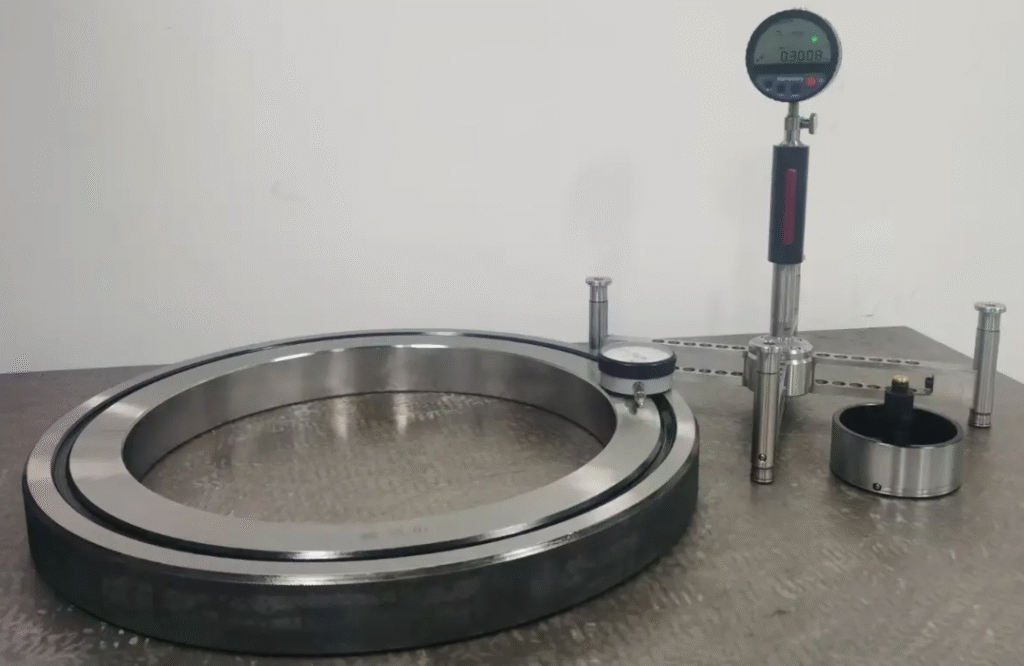
- Bore gauges and plug gauges: for internal diameters; plug gauges ideal for go/no-go assessment of common fits.
- Height gauges and surface plates: for precise height and layout measurements.
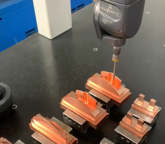
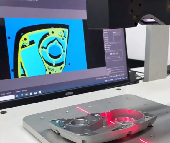
- CMM (coordinate measuring machines): for complex 3D geometries and GD&T evaluations.
Gauge and Instrument Calibration
Measuring instruments themselves must be calibrated periodically using traceable standards. For example:
- Micrometers checked against gauge blocks, typically over their complete measurement range.
- Dial indicators checked for linearity and hysteresis.
- CMMs calibrated using certified artifacts such as step gauges, ball plates, and reference spheres.
Environment during measurement should match the assumed reference temperature (commonly 20 °C). Instruments and parts must be allowed to stabilize to avoid thermal measurement errors.
In-Process and Final Inspection
In-process measurement strategies can include:
- Touch probes on CNC machines to measure critical dimensions before finishing cuts.
- Simple go/no-go gauges at the machine for fast feedback.
- Intermittent removal of parts for micrometer or bore gauge measurement in a nearby measurement area.
Final inspection often uses higher accuracy instruments and may incorporate statistical analysis of measured data to verify process capability. A balance must be struck between measurement frequency and production efficiency; stable processes can rely on sampling, while unstable or newly set processes may require 100% inspection for critical features.
Material and Part Geometry Considerations
Material properties and part geometry significantly influence the strategies required to achieve dimensional accuracy.
Material Properties Affecting Machining Accuracy
Factors include:
- Hardness and strength: harder materials may cause higher tool wear and cutting forces, impacting dimensional consistency.
- Elastic modulus: low stiffness materials (e.g., aluminum, thin stainless) are more prone to elastic deformation and chatter.
- Thermal conductivity: materials with low thermal conductivity (e.g., some stainless steels, titanium alloys) concentrate heat near the cutting zone, increasing thermal distortion and tool wear.
Tailoring cutting parameters and tool grades to each material is essential to avoid unwanted dimensional drift during production runs.
Thin-Walled and Slender Parts
Thin walls, long shafts, and delicate features are especially sensitive to deflection and residual stress. Techniques to control dimensions include:
- Using support fixtures, centers, and steady rests for long workpieces.
- Reducing radial cutting forces: lower depth-of-cut, sharper tools, and adjusted feed rates.
- Using balanced machining: alternate side machining or symmetrical material removal to reduce bending and twisting.
- Applying multiple light finishing passes on critical surfaces instead of a single heavy finishing cut.
Statistical Process Control and Process Capability
Maintaining dimensional accuracy over time requires monitoring variation and adjusting the process proactively. Statistical process control (SPC) is widely used to achieve this.
Monitoring Critical Dimensions
Critical dimensions are monitored by collecting measurement samples over time and plotting them on control charts. For example, an X̄–R chart shows the mean and range of successive samples, allowing identification of trends and sudden shifts.
Key steps:
- Select critical or high-risk dimensions (tight tolerances, safety-related, assembly-critical).
- Define sampling frequency and sample size (e.g., 5 parts per batch, or every 30 minutes).
- Record data systematically and review charts periodically.
Interpreting Process Capability
Process capability indices evaluate how well a process fits within tolerance limits:
- Cp = (USL − LSL) / (6σ), where USL and LSL are upper and lower specification limits, σ is process standard deviation.
- Cpk accounts for centering: Cpk = min[(USL − μ) / (3σ), (μ − LSL) / (3σ)], where μ is process mean.
As a guideline, for reliable production with low defect rates:
- Cp and Cpk ≥ 1.33 for standard quality requirements.
- Cp and Cpk ≥ 1.67 or higher for tighter or safety-critical parts.
When indices are low, possible actions include reducing variation (tool improvements, better fixturing, improved environment) or adjusting the mean (tool offsets, program corrections) to center the process within tolerance.
Common Issues in Achieving Dimensional Accuracy
In practical machining environments, certain recurring issues tend to limit dimensional control:
Variation Between Operators and Shifts
Differences in experience and technique can result in inconsistent tool offset adjustments, clamping methods, and inspection practices. Standardized work instructions, training, and clear offset adjustment rules significantly reduce such variability.
Unstable Tool Life and Wear Patterns
Inconsistent wear leads to unpredictable dimensional shifts within a batch. The main causes include inappropriate cutting data, inconsistent coolant application, and use of tools beyond their reliable wear zone. Defining conservative tool life per operation and adhering to it improves dimensional stability.
Undetected Machine Degradation
Gradual wear of ball screws, ways, and spindle bearings may go unnoticed until dimensional defects become frequent. Systematic machine condition monitoring and scheduled geometric checks help detect these trends before parts fall out of tolerance.
Missing or Incomplete Feedback Loop
If measured deviations are not systematically fed back into process adjustments, the same issues recur. A simple closed-loop logic is effective:
- Measure critical dimensions.
- Compare to control limits and target.
- Adjust tool offsets or process parameters when trends approach limits.
- Verify the effect of adjustments.
Typical Tolerance Levels and Practical Considerations
It is useful to relate general tolerance grades to practical machining routes and efforts. The ISO system of tolerances (IT grades) provides standardized tolerance widths relative to nominal size. For example, for 10–18 mm size range:
| IT Grade | Approx. Tolerance Width (10–18 mm) | Typical Machining Route | Remarks |
|---|---|---|---|
| IT10–IT11 | ~0.14–0.23 mm | General turning, drilling, milling (rough to medium) | Achievable on most general-purpose machines. |
| IT8–IT9 | ~0.039–0.090 mm | Standard CNC turning/milling with finishing passes | Common for standard fits and general mechanical parts. |
| IT7 | ~0.025 mm | Precision turning, boring, reaming, grinding | Requires controlled processes and stable environment. |
| IT6 | ~0.016 mm | Fine boring, precision grinding | Often involves dedicated fixtures and calibrated machines. |
| IT5 | ~0.010 mm | Jig grinding, honing, lapping | Requires high-precision equipment and strict temperature control. |
These values are approximate and serve as guidance. As tolerance becomes tighter, the requirements on machine tool quality, environment, process control, and measurement rigor increase significantly.
Summary and Practical Implementation Path
Achieving dimensional accuracy in machining is the result of coordinated control across the entire production chain. Key elements include:
- Accurate interpretation of drawings and GD&T, with clear linkage between design, machining, and inspection datums.
- Selection and calibration of suitable machine tools for the required tolerance level.
- Robust workholding and fixturing that stabilize the part without introducing harmful deformation.
- Appropriate tooling, cutting parameters, and disciplined tool wear management.
- Control of thermal effects through environmental stability and process strategies.
- Systematic measurement, inspection, and statistical process control with feedback into offsets and process adjustments.
By approaching dimensional accuracy as a system-level objective rather than focusing on any single element, machining operations can produce parts that consistently match design intent while minimizing scrap, rework, and inspection overhead.
FAQ: Dimensional Accuracy in Machining
What is dimensional accuracy in machining?
Dimensional accuracy in machining refers to how closely the actual size of a machined part matches the dimensions specified on the engineering drawing. Higher dimensional accuracy means smaller deviation from the nominal size.
What are the main causes of poor dimensional accuracy?
Common causes include:
Tool wear or incorrect tool geometry
Thermal expansion of the workpiece or machine
Improper fixturing or weak clamping
Incorrect cutting parameters
Machine tool positioning errors
How can dimensional accuracy be improved during machining?
Dimensional accuracy can be improved by:
Using stable fixturing and proper alignment
Selecting correct cutting speed and feed rate
Monitoring tool wear and changing tools on schedule
Applying coolant to control temperature
Using CNC compensation or in-process measurement
Which machining method provides the most stable dimensional accuracy for mass production?
For mass production, preset tooling, CNC control, and automated measurement systems provide the most stable and repeatable dimensional accuracy.
