
Machining operations that produce holes—such as drilling, reaming, boring and milling—almost always generate burrs at the hole entrance, exit, or internal features. These unwanted material protrusions can degrade part functionality, reduce fatigue life, complicate assembly, and introduce safety hazards. Understanding how and why burrs form, how to evaluate them, and how to remove or prevent them is essential for reliable, cost‑effective production.
Fundamentals of Burr Formation in Hole Machining
Burrs are plastically deformed material left attached to the workpiece after cutting. In hole machining, burrs form mainly at points where the cutting edge exits the material or changes cutting direction, especially at hole break‑through or when intersecting features are present.
Primary burr types in machined holes
Machined holes typically show the following burr types:
- Entrance burrs: Found at the tool entry side of the hole; often smaller but critical if the surface is a sealing or locating face.
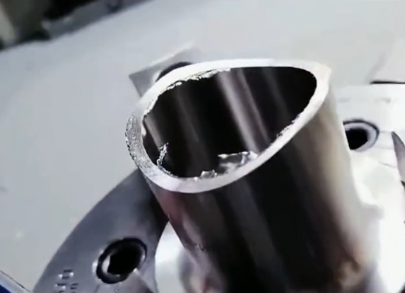
- Exit burrs: Found at the tool exit side; commonly larger and more irregular due to chip pulling and incomplete shearing at breakthrough.
- Intersection burrs: Formed where a hole meets another hole, a groove, or a cavity; often difficult to access and remove.
- Micro-burrs: Very small fringe-like edges that may still affect coatings, sealing, or fatigue performance in precision parts.
From a geometric perspective, burrs may be classified as:
- Poisson burr: Material laterally extruded along the edge without complete separation.
- Rollover burr: Material bent or folded over the edge at breakthrough.
- Tear burr: Material partially torn and attached due to insufficient shearing.
Mechanisms of burr formation
Burr formation in hole machining is dominated by plastic deformation and chip separation mechanisms. When the cutting edge approaches an unrestrained boundary (such as the exit side of a workpiece), the remaining cross‑section often lacks enough support to shear cleanly. Instead, material stretches, bends, and finally tears, leaving a protruding burr root and a fragile burr cap.
Key influencing factors include:
- Workpiece material ductility and hardness
- Tool geometry and edge sharpness
- Cutting parameters (feed, speed, depth of cut)
- Support conditions near the exit (backing plate, fixture design)
- Tool wear and vibration
Typical Burr Problems in Different Hole-Making Operations
Different hole‑making processes tend to generate characteristic burr patterns. Recognizing these patterns helps in diagnosing root causes and selecting suitable corrective actions.
Burrs in drilling operations
Drilling is one of the most common sources of burrs, especially at hole exits.
Frequent drilling‑related burr issues include:
- Large rollover burrs at the exit due to excessive feed at breakthrough
- Irregular tear burrs caused by worn drill lips or chipping
- Entrance chipping and small Poisson burrs from poor centering or workpiece vibration
Conditions that typically aggravate drilling burrs:
High ductility materials: Aluminum alloys, low carbon steels, and some copper alloys tend to form pronounced rollover burrs.
Inadequate backing: Unsupported exit faces promote material flow instead of clean shear.
Suboptimal point geometry: High point angles or incorrect lip relief may increase exit burr formation.
Burrs in reaming and countersinking
Reaming is used to improve accuracy and surface finish but may still generate burrs, especially at the exit side of blind or through holes. Typical outcomes include:
- Fine micro-burrs at the reamed edge affecting sealing surfaces
- Slight rollover due to insufficient cutting edge sharpness
Countersinking and counterboring can create burrs at both the internal edge (where the countersink meets the hole) and the external chamfer circumference, especially when feed is too high or the tool is dull.
Burrs in milling and boring of hole features
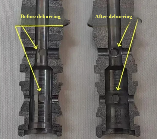
When holes are finished by boring heads or when pockets, slots, and profiles intersect with holes, milling and boring operations can leave intersection burrs inside the component. These burrs are particularly problematic when:
- The burr is hidden inside a hydraulic or pneumatic passage
- Loose fragments risk contaminating fluid systems
- Internal dimensions are tight, limiting deburring tool access
Key Factors Influencing Burr Size and Geometry
Control of burr formation depends on managing the interaction between material, tool, process, and fixture. Understanding these factors allows systematic optimization.
Material properties
Material behavior under cutting forces strongly determines burr size and morphology:
- Ductile metals (e.g., Al, Cu, mild steel): Tend to create larger rollover burrs and Poisson burrs.
- Hard or brittle materials (e.g., hardened steel, cast iron): Often generate smaller burrs but may show edge chipping instead.
- Work‑hardening alloys (e.g., some stainless steels): Can form tough burr roots that are more resistant to removal.
Material heterogeneity, such as inclusions or varying microstructure near the edge, may lead to non‑uniform burrs around the circumference of the hole.
Tool geometry and condition
For drills and similar tools, the following geometric features are especially relevant:
- Point angle: Smaller angles often reduce exit burrs in some materials; larger angles may increase burr size in ductile alloys.
- Lip relief angle and chisel edge design: Influence cutting efficiency and thrust force, affecting burr height at breakthrough.
- Corner chamfer or radius: A small radius can reduce burr severity and make it more uniform.
- Coating and edge preparation: Coatings and honed edges can improve tool life but may slightly change burr behavior.
Tool wear significantly increases burr size. A worn cutting edge plows and smears material instead of cleanly shearing it, promoting larger and more tenacious burrs.
Cutting parameters
Feed rate, cutting speed, and pecking strategy influence burr formation. Typical tendencies include:
- High feed at breakthrough: Often increases exit burr height and thickness.
- Excessively low feed: May cause rubbing and built‑up edge, which can also increase burr irregularity.
- Cutting speed: Optimal ranges depend on material and tool; speeds that promote stable chip formation usually help minimize burrs.
Feed reduction immediately before breakout is commonly used to limit exit burr size, particularly in automated CNC drilling cycles.
Workholding and support
Rigid clamping and adequate backing at the hole exit are crucial. A backing plate or sacrificial layer supports the material and allows cleaner cutting as the tool exits. Poor support typically results in more severe rollover and tear burrs.
Inspection and Measurement of Burrs in Holes
Effective burr control requires quantifiable evaluation. Qualitative visual checks are often supplemented by dimensional measurement to evaluate compliance with edge quality specifications.
Common burr inspection methods
Inspection methods for machined hole burrs vary by part size, accessibility, and required accuracy:
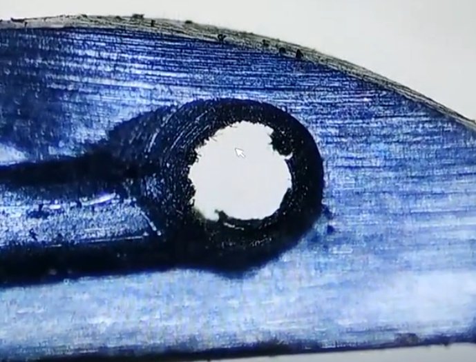
- Visual inspection with magnifiers or microscopes for burr presence, uniformity, and obvious protrusions.
- Tactile assessment using probes or fingernail tests (for non‑critical surfaces) to detect sharp edges.
- Optical measurement systems (profile projectors, digital microscopes) for burr height and width.
- Contact stylus profilometers for quantitative edge geometry in larger features.
- Computed tomography or borescope inspection for internal or hidden burrs in complex parts.
Key burr parameters and acceptance criteria
Typical quantitative parameters include:
- Burr height: Distance from nominal edge to burr tip.
- Burr thickness: Root thickness at the base where it attaches to the edge.
- Burr length: Extent along the edge circumference or feature intersection.
Acceptance criteria often specify maximum allowed burr height, maximum edge radius, or requirements for complete deburring in sealing and functional surfaces. In safety‑critical components, even very small burrs may be unacceptable due to the risk of detachment and system contamination.
Process-Oriented Burr Mitigation Strategies
One of the most efficient approaches is to reduce burr formation at the source through process optimization. This minimizes subsequent deburring cost and time.
Optimizing cutting parameters
Adjusting cutting parameters around the breakthrough phase has a direct impact on burr size. Common strategies include:
- Feed reduction before exit: Program a reduced feed rate for the last portion of the hole depth.
- Controlled peck drilling: Use a peck cycle to manage chip evacuation and tool load, especially in deep or blind holes.
- Appropriate cutting speed: Choose speeds that stabilize chip formation and avoid built‑up edge.
Parameter optimization is typically guided by trial cuts combined with burr measurement, particularly for new material–tool combinations.
Improving tool design and selection
Tool design influences burr behavior significantly. Effective options include:
- Specialized drill geometries designed for low burr formation in specific materials.
- Tools with corner chamfers or radii at the cutting edge to reduce stress concentration and burr severity.
- High‑precision reamers with optimized geometry for minimal micro-burrs on tight tolerance holes.
Maintaining tool sharpness is fundamental. Scheduled tool changes and monitoring of tool wear help prevent sudden increases in burr size and maintain consistent edge quality.
Enhancing workpiece support and fixturing
Providing a backing material or closely supporting the exit surface reduces material deflection and rollover. Solutions include:
- Using sacrificial backing plates under thin workpieces.
- Designing fixtures that closely support the drilling zone on both entry and exit sides where feasible.
- Minimizing overhang and vibration by rigid clamping of the workpiece.
Backing materials should be easy to replace, dimensionally stable, and compatible with the cutting process to avoid contamination or excessive tool wear.
Mechanical Deburring Techniques for Holes
When process optimization does not fully eliminate burrs, mechanical deburring is frequently the first choice due to its simplicity, controllability, and compatibility with many materials.
Manual deburring tools
Hand deburring remains widely used for low‑volume or highly variable work. Tools include:
- Hand scrapers and countersinks: Rotated manually to break sharp edges and remove minor burrs.
- Blade-type deburring tools: Spring‑loaded or hooked blades that follow the hole edge to peel off burrs.
- Files and abrasive stones: For larger edges or when a controlled chamfer is required.
Manual deburring is flexible but can be time‑consuming and operator‑dependent. It is more suitable for small batches or prototype work than for high‑volume production.
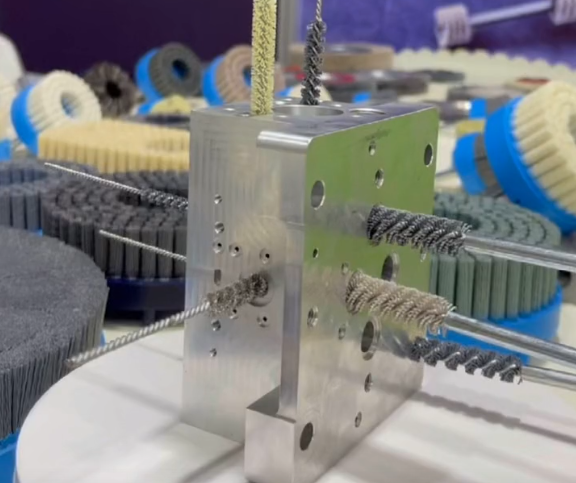
Rotary and power deburring
Power‑driven deburring reduces operator effort and improves consistency. Common methods include:
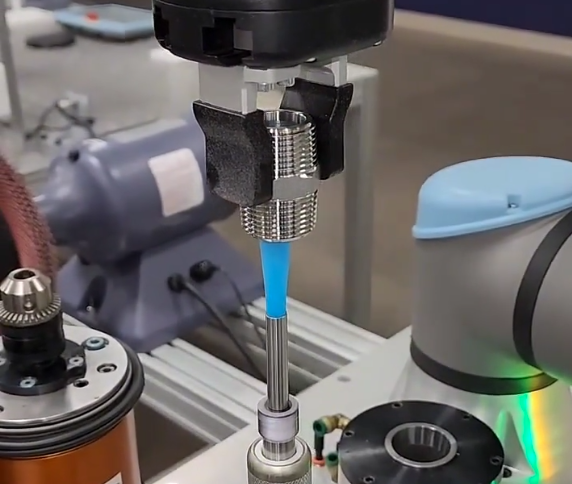
- Rotary brushes: Wire or abrasive nylon brushes mounted on drill presses or CNC machines to sweep burrs from hole edges.
- Rotary deburring cutters: Small countersink or chamfer tools used in hand drills or machining centers.
- Carbide burrs: Rotary burr tools for removing more robust burrs or shaping edges.
Brush deburring is particularly effective for removing small burrs from multiple edges simultaneously, but process parameters (brush type, speed, pressure) must be set carefully to avoid rounding critical edges more than allowed.
Cross-hole and intersection deburring
Internal burrs at cross‑holes and intersections present access difficulties. Specialized solutions include:
- Cross-hole deburring tools with flexible or spring‑loaded heads that expand inside the bore and sweep the intersection.
- Mounted abrasive cones or flap wheels inserted into the main bore to contact intersecting edges.
- Custom‑shaped tools designed specifically for hydraulic manifolds or complex connector blocks.
Tool selection should consider hole diameter, intersection geometry, and required surface finish, as well as permissible chamfer size and tolerance.

Abrasive and Mass Finishing for Hole Deburring
Abrasive‑based and mass finishing methods are widely used when many burr‑bearing features must be treated simultaneously or when manual deburring is impractical.
Important considerations for abrasive deburring
Abrasive methods rely on controlled material removal via abrasive particles or tools. While they can efficiently remove burrs from many edges at once, they also affect overall edge radius and surface roughness. Control of media type, size, and process time is essential to achieve the target condition.
Overview of common methods and applications
| Method | Typical Application | Key Characteristics |
|---|---|---|
| Vibratory finishing | Batch deburring of many small parts with through holes and edges | Good for general burr removal and edge rounding; limited access to deep internal features |
| Tumbling (barrel finishing) | Robust parts requiring uniform edge rounding and surface smoothing | Effective but slower; risk of part‑to‑part impact; not ideal for fragile or precision edges |
| Abrasive flow machining (AFM) | Internal passages, cross‑holes, and complex internal geometries | Abrasive media extruded through passages; capable of reaching internal burrs and improving surface finish |
| Brush deburring with abrasive filaments | Edge honing of drilled and milled holes on CNC machines | Programmable; suitable for integrating into machining cycles; local control of edge condition |
| Micro abrasive blasting | Localized treatment of small holes or sensitive components | Focused abrasive jet; requires masking and careful parameter control |
Thermal and Electrochemical Deburring Methods
Thermal and electrochemical processes are used when burrs are small, numerous, or located in hard‑to‑reach internal features. These methods remove burrs by selectively melting, burning, or dissolving the protruding material.
Thermal energy deburring basics
Thermal deburring uses controlled combustion of a gas mixture in a closed chamber to remove burrs. When ignited, the gas combusts rapidly, and the resulting thermal energy selectively burns off thin burrs exposed to the gas flow while leaving the bulk material mostly intact.
Key attributes:
- Effective for small burrs on complex internal passages, such as manifolds.
- Best suited to metals that can withstand momentary high temperatures without distortion.
- Burrs are removed uniformly from all exposed edges, including internal intersections.
Part design must ensure that all burrs are accessible to the gas mixture and that sensitive components (seals, non‑metal inserts) are removed or protected.
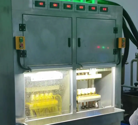
Electrochemical deburring basics
Electrochemical deburring (ECD) is based on controlled anodic dissolution of burr material. A shaped cathode tool is positioned near the burr area, and an electrolytic fluid is circulated in the gap. When current is applied, the anodic workpiece material at high‑current‑density regions (thin burrs and sharp edges) dissolves faster than the surrounding surfaces.
Key features include:
- Contactless removal without mechanical pressure, beneficial for delicate parts.
- Minimal tool wear since removal is electrochemical.
- Good repeatability when process parameters and electrolyte conditions are controlled.
ECD is especially useful for deburring critical edges in fuel system components, gear holes, and hydraulic parts where mechanical methods may deform or damage precise geometries.
Design for Manufacturability and Burr Reduction
Many burr problems can be mitigated during the design stage by adapting features to be more burr‑tolerant or easier to deburr.
Feature design for reduced burr sensitivity
Typical design adaptations include:
- Adding functional chamfers: Specifying controlled chamfers at hole entrances and exits reduces burr sensitivity and sets clear edge quality requirements.
- Adjusting intersection angles: Where possible, orienting intersecting holes or channels to facilitate tool access and uniform deburring.
- Avoiding extremely thin walls near hole exits: Thin unsupported lips tend to deform and produce large rollover burrs.
Designers should collaborate with manufacturing engineers to balance functional requirements with achievable edge quality and deburring capability.
Specifying realistic edge requirements
Edge conditions should be defined clearly in drawings and specifications. Typical ways include:
- Defining maximum burr height or stating “burrs removed, edges broken 0.1–0.3 mm” where appropriate.
- Using standard symbols or notes for chamfers, edge breaks, and permitted radii.
- Indicating critical edges where no burrs or loose particles are allowed, such as sealing surfaces and flow control orifices.
Stating unachievable or overly vague requirements leads to inconsistent deburring and unnecessary cost. Quantitative and function‑based specifications improve communication and process planning.
Quality Control and Process Integration
Burr management is most efficient when integrated into the overall process and quality system, instead of treating deburring as an isolated, manual step.
Process capability and monitoring
Assessing process capability for burr‑related metrics includes:
- Defining measurable burr parameters and acceptable limits.
- Collecting data on burr height or edge condition over time.
- Identifying correlations between tool wear, cutting parameters, and burr size.
Statistical monitoring of burr metrics can reveal trends in tool performance and signal when tool change or parameter adjustment is needed before non‑conforming burrs occur.
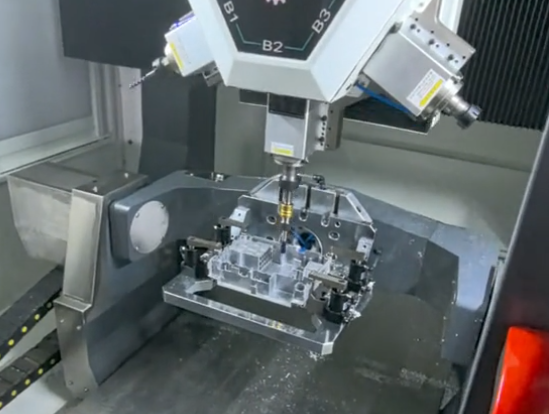
Integrating deburring into machining operations
Integrating deburring into the machining cycle improves consistency and reduces handling. Options include:
- Using CNC‑mounted deburring tools or brushes to treat hole edges directly after drilling or reaming.
- Programming automatic chamfering cycles at entrance and exit edges.
- Combining drilling, deburring, and inspection steps within the same workholding setup where feasible.
This integration minimizes positioning errors, reduces cycle times, and assures that deburring is performed under controlled conditions rather than as a separate, variable manual operation.
Comparison of Common Hole Deburring Methods
Different deburring techniques offer distinct combinations of precision, productivity, and cost. Selecting a method requires aligning process capabilities with part requirements and production volume.
| Method | Suitable for | Precision and Control | Typical Use Case |
|---|---|---|---|
| Manual deburring | Low volumes, varied geometries, prototypes | High operator dependence; good local control on accessible edges | Small batches, repair work, special features |
| CNC integrated deburring (tools/brushes) | Medium to high volumes, repeatable parts | Good repeatability; programmable edge condition | Production of precision components with consistent requirements |
| Mass finishing (vibratory/tumbling) | Many small parts with accessible holes | Less local control; affects all edges; adjustable via media and time | Fastener parts, simple bushings, general hardware |
| Abrasive flow machining | Complex internal passages, cross‑holes | Good internal access; simultaneous smoothing of internal surfaces | Hydraulic manifolds, fuel rails, fluid distribution components |
| Thermal deburring | Small burrs on multiple internal and external edges | Uniform burr removal; limited dimensional impact on main surfaces | Series production of cast or machined components with many passages |
| Electrochemical deburring | Critical edges requiring non‑contact deburring | High local precision near shaped electrodes; minimal mechanical stress | Fuel system parts, precision gears, high‑reliability hydraulic parts |
