
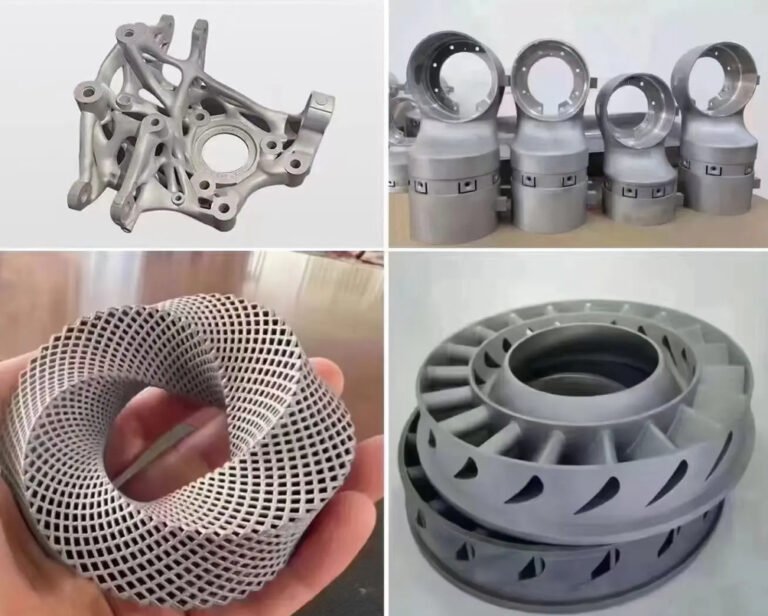
3D metal fabrication—commonly called metal additive manufacturing—enables complex, high‑performance components that are extremely difficult or impossible to produce by conventional machining, casting, or forming. At the same time, the process window is narrow, the output is highly sensitive to design and process parameters, and small deviations can compromise part quality. This page provides a systematic, technically focused overview of how 3D metal fabrication works, where it delivers the most value, and what makes it structurally and operationally fragile.
Core Principles of 3D Metal Fabrication
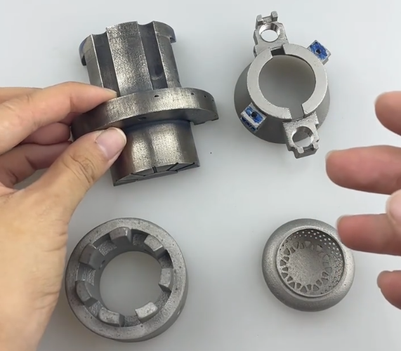
3D metal fabrication builds parts layer by layer using metal feedstock—powder or wire—under computer control. The digital model is sliced into layers, and each layer is created by melting, binding, or depositing material according to toolpaths derived from the geometry.
Key common principles include:
- Layer-wise material addition instead of bulk removal
- Dependence on a 3D CAD model and build file (e.g., STL, 3MF, AMF)
- Thermal cycles that strongly affect microstructure and properties
- Need for post-processing to reach final geometry and performance
The strength of 3D metal fabrication lies in geometric freedom and localized property control, but its fragility arises from the tight coupling between design, process parameters, material condition, and post-processing.

Main Categories of Metal Additive Manufacturing Processes
Multiple process families exist, each with distinct mechanisms, capabilities, and sensitivities. Selecting the right process is critical for dimensional accuracy, mechanical performance, and production economics.
Laser Powder Bed Fusion (LPBF / DMLS / SLM)
Laser Powder Bed Fusion (LPBF) uses a laser to selectively melt regions of a thin metal powder layer spread over a build plate. After each layer is scanned and melted, the build platform lowers, and a new powder layer is applied.
Typical characteristics:
- Layer thickness: ~20–80 μm
- Feature resolution: ~100–150 μm (laser spot and scan strategy dependent)
- Build chamber environment: inert gas (argon, nitrogen) with low oxygen levels
- Feedstock: gas-atomized powder with controlled particle size distribution, often 15–45 μm
LPBF is widely used for aerospace, medical, and high-performance industrial parts due to fine resolution and near‑net‑shape capability. However, it is sensitive to powder quality, laser power stability, optical alignment, recoater behavior, and gas flow conditions.
Electron Beam Powder Bed Fusion (EB-PBF)
Electron Beam PBF uses an electron beam under vacuum to melt pre‑spread powder layers. Preheating of the powder bed results in lower residual stresses compared to laser-based systems and can reduce the risk of cracking in high-temperature alloys.
Key attributes:
- Vacuum environment reduces oxidation
- High build temperature suitable for Ti alloys and nickel-based superalloys
- Coarser surface finish compared to LPBF in many cases
The process is less prone to certain thermal stress-related issues but requires careful control of beam parameters, sintering behavior, and powder reuse cycles.
Binder Jetting with Post-Sintering
Binder jetting deposits liquid binder onto a powder bed to form a “green” part. After printing, the part undergoes debinding and high-temperature sintering, with optional infiltration to increase density.
Characteristics:
- High throughput and large build volumes
- No melting during printing (green parts are fragile before sintering)
- Significant shrinkage during sintering (often 15–20% linear, material-dependent)
Dimensional control relies on accurate shrinkage prediction and uniform thermal processing. Variation in green density and sintering conditions can cause warpage, porosity, and dimensional deviation.
Directed Energy Deposition (DED / LMD / WAAM)
Directed Energy Deposition feeds powder or wire into a small melt pool generated by a laser, electron beam, or electric arc. Material is deposited along a toolpath, enabling the creation or repair of large parts and features.
Key aspects:
- High deposition rates compared to powder bed systems
- Suitable for large structures and cladding/repair operations
- Moderate feature resolution; often followed by machining
The process’s flexibility comes with strong dependence on motion control, melt pool monitoring, shielding gas management, and toolpath planning. Unstable melt pool behavior or poor path overlap can create defects such as lack of fusion and inconsistent bead geometry.
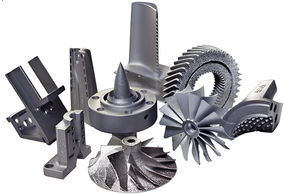
Common Metals and Alloys in 3D Fabrication
Material selection influences mechanical performance, cost, printability, and post-processing. Not all wrought or cast alloys are suitable for additive manufacturing, and AM‑optimized compositions are increasingly used to improve printability and reduce cracking or porosity.
| Alloy System | Common Grades | Typical Applications | Notable Considerations |
|---|---|---|---|
| Aluminum | AlSi10Mg, AlSi7Mg, AlSi12, high-strength Al alloys | Lightweight structural parts, housings, automotive, aerospace | High reflectivity; susceptibility to porosity; careful gas control required |
| Titanium | Ti-6Al-4V (grade 5, 23), Ti-6Al-2Sn-4Zr-6Mo | Aerospace brackets, medical implants, high strength-to-weight parts | Reactive at high temperature; oxygen and nitrogen pickup must be controlled |
| Nickel Superalloys | IN718, IN625, Hastelloy X, CM247-like alloys | Turbine components, hot-section hardware, high-temperature fixtures | Prone to cracking; process parameter windows can be narrow |
| Stainless Steel | 316L, 17-4PH, 15-5PH | General industrial components, tooling, fluid handling, medical instruments | Good printability; properties strongly influenced by post-heat treatments |
| Tool Steel | H13, maraging steels, M300-like steels | Mold inserts with conformal cooling, wear-resistant components | High hardness achievable; residual stress management is important |
| Copper Alloys | CuCrZr, pure Cu, CuNiSiCr | Thermal management, RF components, induction coils | High thermal conductivity and reflectivity challenge laser melting |
Design Considerations: Geometric Freedom with Structural Sensitivity
Design for 3D metal fabrication must accommodate both the advantages and the fragilities of layer‑based manufacturing. Design choices influence residual stresses, support needs, surface quality, and post-processing effort.
Feature Resolution and Minimum Thickness
Features below the process’s effective resolution can be partially formed, distorted, or missing. For LPBF, practical minimum wall thickness is typically around 0.3–0.5 mm depending on material and orientation. Very thin sections may warp, distort, or fail during support removal or post-processing.
Small holes, slots, and lattice struts must be sized above the effective process resolution to avoid partial closure, powder entrapment, or weak connections.
Overhangs, Bridges, and Self-Supporting Angles
Overhanging geometry is constrained by the angle relative to the build plate. Below a certain angle (often ~45° for LPBF, but material and machine dependent), supports are normally required to stabilize the melt pool and control distortion.
Unsupported overhangs may cause:
- Downskin surface roughness and sagging
- Incomplete fusion or collapse when the molten pool lacks adequate underlying support
- Excess residual stress leading to cracking
Design strategies include increasing overhang angles, adding fillets or chamfers, or reorienting the part to reduce unsupported regions.
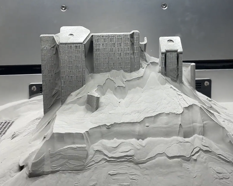
Powder Removal and Internal Channels
Internal channels and cavities are a major advantage of metal AM but introduce challenges for powder removal and inspection. Narrow or tortuous channels can trap powder, which may remain loose or be sintered during heat treatment.
Design measures include:
- Providing access ports large enough for powder evacuation
- Using channel cross-sections less prone to powder blockage (e.g., circular or teardrop)
- Avoiding sharp internal corners where powder can accumulate
When powder cannot be fully removed, the retained powder may interfere with fluid flow, reduce cooling effectiveness, or contaminate downstream systems.
Support Structures: Necessity and Risk
Support structures anchor overhanging features, conduct heat into the build plate, and reduce warpage. However, they add material consumption, build time, and post-processing effort, and they can damage surfaces during removal.
Support Design and Placement
Support strategies involve balancing structural function and removability. Supports may be solid, lattice-like, or line-based. Considerations include:
- Contact geometry: small contact points ease removal but may fail during building
- Thermal path: supports must effectively conduct heat to reduce local overheating
- Access: supports should be accessible for cutting, machining, or blasting
Poorly designed supports can break during the build, causing layer shifting, recoater collisions, or partial part detachment.
Support Removal and Surface Integrity
Removing supports usually involves cutting, grinding, or machining, followed by surface finishing. Risks include:
- Local overheating or hardening if removal involves thermal methods
- Surface gouges, micro-cracks, or residual notches at removal sites
- Geometric deviation when thin features or fine walls are attached to heavy supports
Support removal should be considered at the design stage, ensuring that the geometry near support interfaces can withstand mechanical loads and finishing operations.

Process Parameters and Their Impact on Part Quality
3D metal fabrication is highly parameter‑dependent. Process parameters define energy input, powder spreading, and thermal history. Small deviations can cause porosity, cracks, distortion, or surface anomalies.
Energy Input and Scan Strategy
Key parameters in laser- or beam-based processes include power, scan speed, hatch spacing, layer thickness, and scan pattern. Energy density must be sufficient to fully melt the powder and bond layers without causing excessive evaporation or keyhole instability.
Typical phenomena related to energy input:
- Low energy: lack of fusion defects, lack of bonding between tracks/layers, high porosity
- High energy: keyholing, vaporization, spatter, balling, and local microstructural changes
- Non-uniform scan strategy: anisotropic residual stresses and distorted geometries
Scan strategies often use alternating directions, island scans, or contour plus hatch approaches to distribute heat and control distortion, but these configurations need validation for specific geometries and materials.
Powder Layering and Recoater Behavior
Powder layering quality affects density, surface finish, and defect occurrence. The recoater (blade or roller) must spread a consistent, thin layer of powder across the bed.
Critical factors include:
- Powder size distribution, shape, and flow characteristics
- Recoater speed, blade material (e.g., rubber, ceramic, steel), and gap settings
- Bed flatness and previous layer topography
Interrupted powder spreading, streaks, or gouging can lead to local voids, dimensional errors, or machine stoppage. Interaction between tall supports or thin walls and the recoater can cause bending or breakage, and in severe cases, damage to the recoater or optics.
Atmosphere, Gas Flow, and Contaminants
In powder bed systems, process gas composition and flow affect oxidation, fume removal, and spatter transport. Controlled oxygen content is essential for reactive alloys, and gas flow must evacuate fumes without disturbing the powder layer.
Typical gas-related considerations:
- Oxygen levels: often maintained below 1000 ppm, with stricter limits for some materials
- Filter loading: accumulation of condensate and particles on filters alters flow patterns
- Flow uniformity: insufficient or non-uniform flow promotes soot buildup on optics and surface defects
Contaminant accumulation can change melt pool behavior and reduce laser absorption consistency, impacting mechanical properties and surface finish.
Dimensional Accuracy, Tolerances, and Surface Finish
Dimensional accuracy and surface quality in metal AM are influenced by thermal shrinkage, residual stress relief, scanning strategy, support removal, and post-processing. Published nominal tolerances are often conditional and may not apply uniformly across complex geometries.
Dimensional Deviation Sources
Primary sources of dimensional deviation include:
- Thermal contraction during solidification and cooling
- Elastic and plastic deformation due to residual stresses
- Support removal forces and post-processing loads
- Layer stair-stepping on inclined surfaces
Certain geometries tend to oversize or undersize systematically. Compensation strategies such as scaling the CAD model, applying offset contours, or locally adjusting scan parameters are often used but require empirical calibration.
Surface Roughness and Its Implications
Surface roughness in metal AM is typically higher than in machined parts. Roughness varies between upskin, downskin, and side surfaces, and between supported and unsupported regions.
Typical roughness ranges for LPBF surfaces can be in the order of Ra 8–20 μm for as-printed surfaces, depending on material and process. Down-facing surfaces and internal channels exposed to powder may exhibit higher roughness and partially fused particles.
High roughness impacts:
- Fatigue performance due to stress concentration at surface asperities
- Fluid flow behavior and pressure drop in channels
- Mating interfaces and sealing surfaces
Mechanical or chemical finishing steps are commonly required for critical surfaces.
Mechanical Properties and Microstructure Control
Metal AM parts exhibit microstructures and mechanical properties that can differ significantly from wrought or cast counterparts. Layer-wise solidification and repeated thermal cycling produce fine microstructures and anisotropy.
As-Built vs Post-Processed Properties
As-built parts often have high strength due to fine microstructures but may exhibit lower ductility, residual stress, and potential micro-defects. Properties can be modified via heat treatment, hot isostatic pressing (HIP), and thermomechanical processing.
Typical differences include:
- Yield strength: often higher than equivalent wrought properties for some alloys
- Ductility: may be lower in as-built condition; enhanced by stress relief and HIP
- Fatigue performance: strongly dependent on defect population and surface condition
Heat treatment schedules must be matched to alloy composition and desired performance, with attention to potential phase transformation, grain growth, and precipitation behavior.
Anisotropy and Build Orientation Effects
Mechanical properties can vary with build orientation due to microstructural alignment, defect orientation, and layer interfaces. Components loaded perpendicular to build layers may experience different fatigue and fracture behavior than those loaded along the layer plane.
Design and qualification must account for anisotropy by testing specimens extracted in multiple orientations and adjusting design factors accordingly.
Post-Processing: From Near-Net Shape to Functional Part
Post-processing is integral to 3D metal fabrication. It transforms the fragile as-built structure into a functional, fully qualified part. Steps may be optional or mandatory depending on application and quality requirements.
Common Post-Processing Steps
Typical post-processing sequence may include:
- Support removal and part separation from the build plate
- Stress relief heat treatment to reduce residual stresses
- HIP to close internal porosity and improve fatigue performance
- Machining of critical interfaces, holes, and tolerance-critical surfaces
- Surface finishing (shot peening, abrasive flow machining, polishing, chemical milling)
- Coating or surface treatment for wear, corrosion, or thermal properties
Each step adds variability and must be controlled to maintain geometry, surface integrity, and material properties.
Heat Treatment and Distortion
Stress relief and other heat treatments can relax residual stresses and change microstructure but may also introduce distortion if heating and cooling are not uniform or if fixturing is insufficient.
Considerations include:
- Heating rates and soak times appropriate for section thickness
- Part orientation and support during heat treatment to minimize creep and sagging
- Use of fixtures that constrain critical features without over‑constraining thermal expansion
Thermal cycles should be established experimentally and through simulation for critical hardware.
Powder Handling, Reuse, and Material Stability
Metal powder condition directly influences process stability, part density, and mechanical properties. Powder is a core asset in AM workflows but also a potential source of variability and fragility.
Powder Quality and Storage
Key powder attributes include particle size distribution, morphology, chemical composition, and contamination levels. Deviations can change flow behavior, packing density, and laser absorption characteristics.
Precautions for powder management:
- Dry, inert storage to prevent oxidation and moisture uptake
- Controlled sieving to remove oversized particles and agglomerates
- Monitoring of oxygen, nitrogen, and hydrogen content, particularly for reactive alloys
Repeated reuse cycles alter powder characteristics due to thermal exposure, oxidation, and mixing with spatter and condensate. Reuse strategies must be validated through regular powder characterization and mechanical testing.
Contamination and Cross-Material Risks
Cross-contamination between different alloy powders can occur during handling, sieving, or storage. Small amounts of foreign material can significantly change mechanical behavior and corrosion performance, especially in high-purity or medical applications.
Segregated handling, dedicated equipment, and traceability procedures reduce contamination risk. Cleaning protocols for machines and powder handling systems should be documented and verified.
Inspection, Qualification, and Data Requirements
Because of the sensitivity of metal AM to process fluctuations, thorough inspection and qualification protocols are needed to ensure that parts meet specifications and that process changes are controlled.
Non-Destructive and Destructive Testing
Non-destructive testing (NDT) methods such as X-ray computed tomography (CT), ultrasonic inspection, dye penetrant testing, and radiography can reveal internal and surface defects. CT is often used for complex internal geometries and lattice structures.
Destructive testing supports qualification and monitoring of ongoing production through tensile tests, hardness measurements, fracture toughness, and fatigue testing. Coupons built alongside production parts or within the build envelope can represent local process conditions.
Process Monitoring and Traceability
Many systems incorporate in-situ monitoring, including melt pool sensors, layer-wise imaging, and acoustic sensors. These data help detect anomalies during fabrication, but effective use requires defined evaluation criteria and correlation to part quality.
Traceability measures may include:
- Recording machine parameters, gas conditions, and build logs
- Tracking powder batch history and reuse cycles
- Documenting post-processing routes and heat treatment cycles
Comprehensive documentation is essential for regulated sectors such as aerospace and medical implants, where each part’s history must be demonstrable.

Cost Drivers and Production Planning
While 3D metal fabrication can consolidate assemblies and reduce tooling, its cost structure is influenced by machine time, material utilization, post-processing, quality assurance, and yield. Understanding these drivers is important for realistic planning.
| Cost Driver | Description | Influence on Part Economics |
|---|---|---|
| Build Time | Layer count, scan length, and process parameters | Directly affects machine hourly cost and throughput |
| Material Utilization | Powder cost, refresh rate, supports, overflow | Impacts per-part material cost and waste factor |
| Post-Processing | Heat treatment, HIP, machining, surface finishing | Can exceed printing cost for high-precision parts |
| Inspection and Qualification | NDT, CT scans, mechanical testing, documentation | Significant for safety-critical or regulated components |
| Yield and Scrap | Build failures, out-of-tolerance parts, defects | Reduced yield increases effective cost per good part |
| Process Setup and Engineering | Design adaptation, support optimization, parameter tuning | High upfront effort, especially during first article development |
Typical Failure Modes and Fragilities
3D metal fabrication can produce robust components, but the process chain has multiple points where failures can arise. Understanding typical failure modes enables more reliable design and planning.
Build Interruptions and Part Detachment
Builds can be interrupted by power loss, software errors, recoater collisions, or detection of process anomalies. Once interrupted, many builds cannot be resumed without compromising part integrity. Part detachment from the build plate or supports can cause substantial damage to both part and machine, including recoater and optics.
Internal Defects and Hidden Inconsistencies
Defects such as lack of fusion pores, gas porosity, cracks, and inclusions may be distributed non‑uniformly. Internal defects are often invisible externally, yet they can dominate fatigue life and fracture behavior. Without appropriate inspection, parts may appear acceptable while containing critical defects.
Geometric Distortion and Out-of-Tolerance Features
Residual stresses and thermal gradients can distort parts during or after the build. Post-processing steps such as heat treatment, machining, and support removal may further shift geometry. For tight-tolerance assemblies, accumulated deviations can produce misalignment, interference fits, or loss of sealing functions.
Practical Considerations for Implementing 3D Metal Fabrication
Implementing 3D metal fabrication involves more than acquiring a machine. It requires careful integration of design, materials, process engineering, post-processing, and quality assurance.
Design Workflow Integration
Effective use of metal AM involves design teams that understand process capabilities and restrictions. Integration with simulation tools for thermal behavior, distortion prediction, and support optimization helps reduce trial-and-error. Data feedback from manufacturing and inspection should inform design updates.
Process Control and Documentation
Consistent part quality demands defined procedures for powder management, machine calibration, parameter selection, and post-processing. Documentation should include standard operating procedures, calibration logs, material certificates, and inspection reports. Controlled change management is needed whenever parameters, powder source, or post-processing conditions are modified.
FAQ
What is 3D metal fabrication?
3D metal fabrication refers to manufacturing metal parts using additive manufacturing technologies, often combined with post-processing steps such as heat treatment, machining, and surface finishing to achieve final specifications.
When does 3D metal fabrication make the most sense?
3D metal fabrication is most effective for complex geometries, low-to-medium production volumes, rapid iteration, and applications where weight reduction or internal features provide functional advantages.
What materials are commonly used in 3D metal fabrication?
Common materials include stainless steels, aluminum alloys, titanium, Inconel, and tool steels. Material selection affects printability, mechanical properties, and post-processing requirements.
How accurate is 3D metal fabrication compared to machining?
Dimensional accuracy in metal 3D printing depends on the process, material, and geometry. For many LPBF systems, achievable dimensional tolerances for small, well-supported features can be on the order of ±0.1–0.2 mm without machining, but complex parts, large spans, and overhangs can deviate more due to distortion and support removal effects. Machining is often used on critical interfaces to reach tighter tolerances comparable to precision CNC machining.
How do you evaluate the cost of 3D metal fabrication?
Cost is influenced by build time, material usage, machine utilization, post-processing, and quality requirements. Evaluating total cost requires looking beyond the printed part alone.
