
CNC machining is precise and versatile, but it is not without constraints. Understanding its practical limitations helps engineers and buyers design manufacturable parts, control cost, and achieve reliable quality.
Overview of CNC Machining Capabilities and Boundaries
CNC machining covers milling, turning, drilling and related operations driven by computer-controlled toolpaths. These processes can reach tight tolerances, produce complex geometries and work with many metals and plastics. At the same time, accuracy, cost and lead time are strongly influenced by tool access, setup strategy, machine rigidity, material behavior and workholding.
Limitations arise from the interaction of machine structure, cutting tools, fixturing, cutting parameters and part geometry. They manifest as dimensional deviations, surface quality issues, extended cycle time, higher scrap risk and increased tooling or setup cost.
Dimensional Accuracy and Tolerance Constraints
CNC machines can hold precise dimensions, but only within certain ranges and under controlled conditions. Tighter tolerances tend to increase machining time, inspection effort and overall cost.
Typical Tolerance Ranges
Common production CNC work often targets general tolerances of ±0.05 mm to ±0.1 mm for non-critical features. With optimized setups and stable conditions, tighter tolerances are achievable, but not uniformly across all sizes and features.
| Feature type / condition | Typical tolerance range | Notes |
|---|---|---|
| General milled dimensions (non-critical) | ±0.05 mm to ±0.10 mm | Standard production parts, moderate size |
| Precision milled features | ±0.01 mm to ±0.02 mm | Requires stable environment and careful process control |
| Turned diameters (short parts) | ±0.005 mm to ±0.02 mm | Lathe work is often more accurate within limited length |
| Fits for shafts and holes | ISO fits (e.g., H7/g6) | May require reaming, grinding or honing |
| Long parts (high L/D ratio) | ±0.05 mm or more | Deflection, vibration and thermal effects dominate |
Actual achievable tolerance depends on machine class, part size, material, tooling and inspection capability. Specifying unnecessarily tight tolerances across the drawing often leads to avoidable cost and low yield.
Factors That Limit Accuracy
- Machine geometry and backlash in ball screws, guides and rotary axes
- Thermal growth of the machine structure and the workpiece
- Tool deflection under cutting forces, especially for long or small-diameter tools
- Workpiece deflection and vibration for thin-wall or slender parts
- Tool wear, especially in abrasive materials or long production runs
These factors cause dimensional drift, taper, out-of-roundness, or mismatch between features from different setups. Compensation methods exist (e.g., tool offsets, probing, controlled warm-up), but they cannot fully remove all deviations.
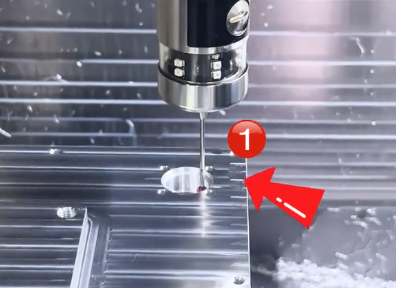
Geometric Complexity and Tool Access Limitations
CNC milling and turning are fundamentally subtractive, line-of-sight processes. Cutting tools must reach the surfaces to be machined with adequate clearance. This creates intrinsic limits on what shapes can be produced efficiently.
Tool Reach and Minimum Feature Size
Small end mills enable fine details, but they are fragile and easily deflected. Deep, narrow cavities or slots strongly constrain tool selection and cutting parameters.
| Feature | Common practical limit | Considerations |
|---|---|---|
| Minimum end mill diameter for production work | 0.5 mm to 1.0 mm | Smaller tools possible, but with very low material removal rate |
| Depth-to-diameter ratio for end mills | Up to 5:1 (standard), 8–10:1 (special cases) | Beyond this, deflection and chatter increase sharply |
| Pocket depth for small-radius corners | Limited by tool length and stiffness | Very deep pockets with sharp corners are costly or unfeasible |
| Minimum internal corner radius | ≈ tool radius (e.g., 0.5 mm tool radius) | Perfectly sharp internal corners are not achievable by milling |
| Sidewall straightness in deep cavities | Deviations increase with depth | Tool runout and deflection cause taper or waviness |
In milling, straight vertical walls deeper than several times the tool diameter become progressively harder to maintain within tight tolerances. Excessive stick-out of the tool leads to vibration, poor surface finish and accelerated tool wear.
Undercuts and Hidden Surfaces
Undercuts and back-side features that are not visible from a single tool direction require specialized tooling or multiple setups. Limitations include:
- Standard end mills cannot machine features obstructed by overhanging geometry
- Undercut tools (T-slot, lollipop, dovetail) have limited reach and reduced stiffness
- Complex multi-axis machines can reach more faces but are still constrained by tool geometry and collision risks
Completely enclosed internal cavities without openings cannot be produced by CNC machining alone, because the cutting tool needs access. Such shapes typically require alternative processes or multi-part assemblies.
Multi-Axis Machining Constraints
5-axis machining improves access and allows machining of complex shapes in a single setup, but it introduces its own constraints:
Tool orientation is limited by machine kinematics, rotary axis stroke and risk of collision between spindle, holder, workpiece and fixture. Near-singular positions or extreme tilts can reduce accuracy. Programming and verification must consider these limits, otherwise some surfaces remain unreachable or must be compromised by using smaller tools and lower cutting parameters.
Surface Finish Limitations
CNC machining can produce very good surface finishes, but the achievable roughness is constrained by tool geometry, feed marks, vibration and material characteristics.
Factors Affecting Surface Roughness
Key factors that limit surface finish include:
- Tool nose radius or cutter diameter (larger radii can improve finish but affect detail)
- Feed per revolution or per tooth, which directly creates scallop height
- Cutter runout and imbalance, leading to uneven tooth loading
- Spindle speed limits and the inability to reach optimal cutting speed
- Machine vibration or chatter, especially on thin sections or weak setups
- Material properties, such as hardness, ductility and tendency to form built-up edge
Typical milled surface roughness ranges from Ra 1.6–3.2 μm for standard finishing passes. With optimized conditions, surface roughness around Ra 0.4–0.8 μm is attainable on suitable materials. Very low roughness values may require subsequent grinding, lapping or polishing.
Toolpath and Step-Over Effects
In 3D contour milling, residual scallops between tool paths define the theoretical roughness and geometric accuracy. Smaller step-over reduces scallop height but multiplies cycle time. At some point, machine positioning resolution and thermal drift dominate, providing diminishing returns for further reduction in step-over.
On turned parts, the combination of feed per revolution and nose radius governs the theoretical surface roughness. Extremely low feed rates improve finish but increase cycle time and can promote rubbing rather than cutting, especially on hardened materials.

Material-Related Machining Limitations
Different materials impose different constraints on tool wear, achievable tolerances, surface finish and cycle time. CNC machining is not equally efficient for all alloys and polymers.
Hard and Abrasive Materials
Materials such as hardened steels, nickel-based superalloys and certain ceramics are difficult to machine because of high hardness, toughness or abrasiveness. Limitations include:
Reduced cutting speeds to control tool wear and heat, leading to longer cycles. Cutting forces are higher, increasing risk of tool breakage and part distortion. Tolerances may be harder to hold over long runs as tools wear rapidly. Specialized tooling (coatings, carbide grades, CBN or PCD) and rigid machines are often necessary, which increases cost.
Soft, Ductile or Gummy Materials
Soft aluminium, pure copper, some stainless steels and certain plastics can exhibit built-up edge on the cutting tools, smearing on the surface and difficulty maintaining dimensional stability. Challenges include:
Chip evacuation problems when chips form long strings, causing recutting or scratching. Surface tearing or burr formation that requires extensive deburring. Part distortion under clamping pressure, especially for thin-wall features or low-modulus plastics. These limitations must be addressed through appropriate tool geometry, sharp edges, coolant strategy and tailored cutting parameters.
Thermal and Dimensional Stability
Some polymers and composites have significant thermal expansion and creep. This can limit achievable tolerances and long-term dimensional stability. Machining heat or aggressive clamping can permanently deform the part. For such materials, tolerance expectations may need to be relaxed or the design adapted to minimize stress concentrations and localized heating.
Wall Thickness, Feature Size and Structural Stability
Thin walls, small bosses, ribs and fragile features are highly sensitive to cutting forces and clamping pressure. They are a frequent source of dimensional variation and scrap.
Minimum Wall Thickness
For metals, walls thinner than about 0.5–1.0 mm are difficult to machine reliably, especially at heights several times the thickness. For plastics, minimum practical wall thickness is often higher due to lower modulus and higher deformation under load. Even when cutting is technically possible, maintaining straightness and avoiding chatter on very thin walls is challenging.
Small Holes and Threads
Micro-holes and very fine threads are limited by tool strength and alignment. Short, small-diameter drills are prone to breakage and wander, especially in hard materials or at high aspect ratios. Tapped holes below certain diameters may require specialized machines, slow speeds and dedicated tapping strategies.
Very small internal threads may not be reliably gauged with standard inspection tools, complicating quality control. Thread milling is an option but increases cycle time and requires accurate interpolation.
Tooling and Tool Life Limitations
CNC machining performance depends heavily on cutting tools. Tool geometry, material and condition impose limits on achievable accuracy, finish and productivity.
Tool Wear and Degradation
As tools wear, cutting forces increase, surface finish deteriorates and dimensional accuracy drifts. For tight-tolerance parts, tool life must be managed carefully through:
Predefined tool change intervals based on experience or monitoring. In-process gauging to detect dimensional shifts and compensate offsets. Conservative cutting parameters to extend tool life, at the cost of longer cycle times.
Limitations occur when tool wear is unpredictable, for example in highly abrasive or non-homogeneous materials. In such cases, process capability can be limited and scrap risk elevated.
Tool Length and Rigidity
Tools with long overhang are required for deep cavities or complex features, but they reduce rigidity drastically. Limitations include:
Lower permissible feed rates and depths of cut to avoid chatter. Increased sensitivity to spindle runout and imbalance. Amplified deflection leading to tapered walls and dimensional errors.
These effects restrict the maximum practicable depth of certain features and may require design modifications such as adding larger corner radii, dividing deep pockets into steps, or revising wall heights.
Machine Hardware and Motion Control Limitations
The mechanical and control systems of CNC machines set fundamental boundaries on positioning accuracy, repeatability and dynamic performance.
Positioning Resolution and Repeatability
Most modern CNC machines offer micron-level command resolution, but actual positioning accuracy is influenced by:
Ball screw pitch errors and backlash. Straightness and squareness errors of guideways. Rotary axis indexing accuracy and wobble. Thermal drift of the machine structure. Controller compensation can reduce but not eliminate these imperfections. Over very large travels or at extreme machine positions, deviation may increase.
Dynamic Performance and Acceleration
Rapid movement and high acceleration enable shorter cycle times, but they introduce dynamic limitations. Heavy tables or large parts require lower acceleration to avoid vibration and overshoot. When machining complex contours at high speed, the controller may limit feed rates to respect axis acceleration constraints, especially around tight corners or small radii.
This can affect surface quality and lead to slightly different tool paths than theoretically programmed (look-ahead filtering, corner rounding), which in turn limits the fidelity of sharp internal features and high-frequency surface details.
Workholding and Fixturing Constraints
Reliable fixturing is critical for precision and repeatability. However, workholding options are limited by part geometry, size, material and access requirements.
Clamping Distortion
Thin walls, large flat plates and flexible components can deform under clamping forces. When the part is released, it springs back, causing out-of-tolerance conditions. Balancing clamping force with process forces is often difficult for lightweight or delicate parts.
Spread-out, balanced clamping and support points can mitigate distortion, but they may obstruct tool access. Vacuum fixtures are useful for flat panels but limited by available vacuum force and the requirement for sufficient contact area.
Multiple Setups and Datum Transfer
Complex parts rarely can be completed in a single setup. Every time a part is re-clamped, there is a risk of datum misalignment, causing feature mismatch or cumulative positional error. Limitations include:
Increased non-cutting time for setup and alignment. Need for precise locating features or custom fixtures. Difficulty maintaining tight positional tolerances between features machined in different setups.
Multi-axis machines and integrated workholding systems reduce setups but do not completely eliminate datum transfer issues, particularly in long, flexible or asymmetric parts.
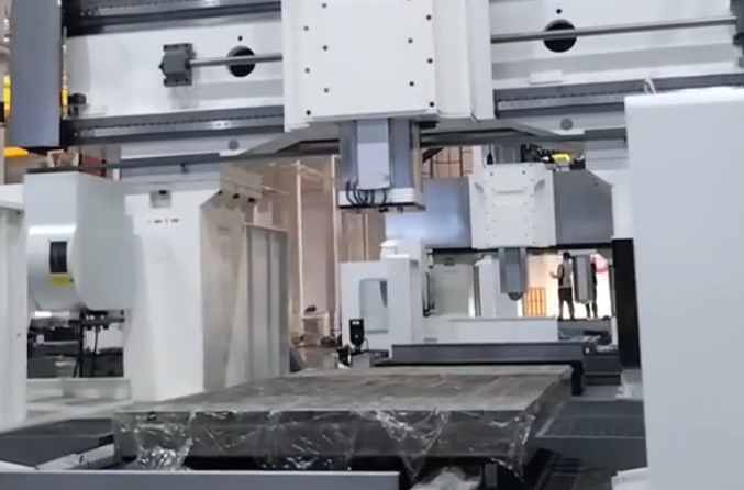
Part Size, Envelope and Weight Limitations
Each CNC machine has a finite working envelope and maximum load capacity. Oversized parts or assemblies require specialized equipment or alternative processes.
Travel and Clearance Limits
Machine X, Y, Z travels define the maximum reachable part dimensions in each direction. Additional limitations include:
Spindle-to-table distance restricting maximum part height or fixture stack-up. Interference between rotary tables, fixtures and the spindle head during 5-axis operations. Clearance needed for tool changes, coolant nozzles and chip evacuation.
Very small parts also present challenges, as fixturing, probing and tool access become difficult. For micro-scale features, conventional machines may not achieve required resolution or stability.
Weight and Inertia
Tables and rotary axes have maximum load ratings. Exceeding them risks reduced accuracy, overloading drives, or safety hazards. Even near the limit, heavy parts may reduce acceleration and dynamic response, impacting cycle time and contour accuracy.
Heat Generation and Thermal Effects
Cutting processes generate heat in the tool, chip and workpiece. Thermal effects can cause transient dimensional changes and residual stresses that limit part accuracy and stability.
Thermal Drift During Machining
As machining progresses, the part temperature can rise, causing expansion. If dimensions are measured while the part is hot, they may be out of specification once cooled, or vice versa. Limitations arise when:
Parts have large mass or long machining times, leading to significant temperature gradients. Materials have high thermal expansion coefficients. Coolant is insufficient to control temperature or is used inconsistently between passes.
Machine structures also expand during prolonged operation. Temperature compensation routines help, but cannot fully remove all drift, particularly in shops without controlled ambient temperature.
Residual Stresses and Distortion
Machining redistributes residual stresses in the material, especially in rolled plate, castings or weldments. When large volumes of material are removed, parts may warp or twist. This limits the ability to hold tight flatness and straightness tolerances in a single operation.
Stress-relief heat treatment or rough machining followed by rest and finish machining can mitigate these effects but add process steps and time.
Programming, Data and Process Control Limitations
Even with advanced CAM software and controllers, CNC processes are limited by the quality of programming, data integrity and process monitoring.
Toolpath Approximation and Interpolation
Complex shapes are approximated by linear or circular segments in the CNC program. Limitations include:
Finite resolution of interpolation, which can introduce small geometric deviations on freeform surfaces. Controller look-ahead and smoothing that may slightly alter the intended path to maintain stable feed rates. File size constraints or performance limitations when very dense toolpaths are used.
For high-precision surfaces, these approximations may require additional finishing strategies or slower feeds to reduce geometric error.
Process Variation and Monitoring Limits
Tool wear, material variation, coolant condition and environmental changes cause process variation. Without adequate monitoring (e.g., in-process gauging, spindle load sensing, tool break detection), limitations appear as inconsistent quality, unexpected tool failures and unplanned downtime.
Even with monitoring, reaction mechanisms such as automated offset updates or adaptive control have limits. Sudden tool breakage, extreme material inclusions or fixture slippage cannot always be compensated in real time and may require manual intervention or part rejection.
Cost and Lead Time Considerations Driven by Limitations
Design decisions that push the boundaries of CNC machining capability usually increase cost and extend lead time. Certain combinations of geometric, material and tolerance requirements move parts into a high-risk, low-yield zone.
Cost Drivers Linked to Machining Limits
Key cost drivers include:
- Very tight tolerances over large dimensions or across many features
- Deep cavities, thin walls and small radius internal corners
- Difficult-to-machine materials requiring premium tooling and slow cutting
- Multiple setups and complex fixtures to reach all features
- High scrap risk due to difficult features late in the process route
Recognizing these limitations at the design stage allows optimization of features, tolerances and material choices, leading to more stable processes and better cost-performance balance.


Design and Planning Strategies to Work Within CNC Limitations
While the limitations of CNC machining cannot be eliminated, they can be managed and mitigated by appropriate design, process planning and quality control approaches.
Design for Manufacturability Practices
Effective strategies include:
Using standard hole sizes, thread forms and fits where possible. Designing internal corner radii that match or exceed standard tool radii. Avoiding extremely thin walls, deep slender ribs and inaccessible features. Grouping tight tolerances only on function-critical dimensions. Selecting materials with good machinability when functional requirements allow.
Process Planning and Quality Control
From the manufacturing side, limitations can be addressed by:
Choosing machines and fixtures that provide adequate rigidity and access. Sequencing operations to minimize distortion, for example by roughing before stress relief and final finishing. Setting realistic tolerance bands based on process capability studies. Implementing suitable inspection strategies such as in-process probing and targeted measurement plans on critical features.
When design and process planning are aligned, CNC machining can deliver consistent, accurate parts while respecting the inherent technical constraints described above.
FAQ About CNC Machining Limitations
What are the main limitations of CNC machining?
CNC machining is limited by tool accessibility, machine size, material hardness, part geometry, and tolerance requirements.
Are there design features that CNC machining cannot produce?
Yes, features such as sharp internal corners, deep narrow cavities, and complex undercuts can be difficult or impossible without special tooling or multi-axis machines.
Is CNC machining suitable for all materials?
CNC machining supports many materials, but very hard, brittle, or heat-sensitive materials may cause excessive tool wear or require specialized equipment.
Can CNC machining produce fully enclosed internal cavities?
No. CNC machining is a subtractive process that requires tool access to remove material. Fully enclosed cavities without any opening cannot be created directly, because the tool must enter and exit the cavity. Such shapes are typically realized by assembling multiple components, using alternative processes like casting or additive manufacturing, or combining methods such as machining plus EDM.
How does CNC machining compare to other manufacturing methods?
CNC machining offers high accuracy and flexibility but may be less cost-effective for very high-volume production compared to casting or molding.
