

CNC quality control is the systematic set of activities that ensures machined parts meet specified requirements for dimensions, geometry, surface finish, material condition, and functional performance. It covers planning, in-process verification, final inspection, data analysis, documentation, and continuous stabilization of the machining process.
Fundamentals of CNC Quality Control
CNC machining converts digital models into physical parts. Quality control ensures that each step from CAD/CAM to finished part remains within defined limits. A robust system integrates people, equipment, methods, and data.
Core objectives of CNC quality control include:
- Verify conformity of parts to drawings, CAD models, and specifications.
- Maintain process stability and repeatability across batches and time.
- Detect nonconformities early, before value-adding operations accumulate.
- Provide traceable evidence of compliance for customers and regulators.
Effective CNC quality control combines standardized procedures, calibrated measurement, trained operators, and appropriate statistical techniques applied to relevant characteristics.
Quality Requirements and Technical Specifications
Quality control starts with understanding and translating requirements into measurable technical specifications. For CNC parts, these requirements are typically defined on engineering drawings and 3D models.
Key elements include:
- Dimensional tolerances for linear and angular features.
- Geometric tolerances defined by GD&T standards.
- Surface roughness and surface integrity requirements.
- Material type, hardness, heat treatment condition, and coating.
Quality control plans must prioritize critical-to-quality (CTQ) characteristics such as interfaces, sealing surfaces, alignment features, and safety-related dimensions, and assign appropriate inspection methods and sampling plans to each of them.
Dimensional and Geometric Tolerances
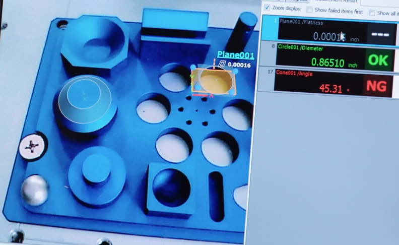
Dimensional tolerances define allowable variation in size and angle, while geometric tolerances control shape, orientation, location, and runout. Together they determine the measurable boundaries of acceptable CNC parts.
Typical linear tolerance ranges in precision CNC machining include:
- General machining: ±0.050 mm to ±0.100 mm
- Precision machining: ±0.010 mm to ±0.025 mm
- High precision/critical features: ±0.002 mm to ±0.005 mm (depending on capability)
Common geometric tolerances applied to CNC parts include flatness, straightness, circularity, cylindricity, parallelism, perpendicularity, angularity, position, concentricity, and runout. These tolerances are specified using GD&T according to standards such as ISO 1101 or ASME Y14.5, and are interpreted via feature control frames and datum reference frames.
Surface Finish and Surface Integrity Control
Surface finish is often a key functional requirement in CNC parts affecting friction, sealing, fatigue, and aesthetics. Surface roughness is commonly quantified using parameters such as Ra (arithmetical mean roughness), Rz (average maximum height of the profile), and sometimes Rt (total height of the profile).
Typical ranges for turned and milled surfaces:
| Process | Typical Ra Range (µm) | Comment |
|---|---|---|
| Rough milling/turning | 3.2 – 12.5 | Intended for stock removal; not for functional surfaces |
| General finish milling/turning | 1.6 – 3.2 | Standard functional surfaces |
| Fine finish milling/turning | 0.4 – 1.6 | Precision contact or sealing surfaces |
| Grinding | 0.1 – 0.4 | High precision and wear-critical surfaces |
| Superfinishing / lapping | 0.025 – 0.1 | Very high precision surfaces |
Quality control for surface finish includes:
- Specifying roughness parameters and limit values on drawings.
- Using calibrated contact profilometers or optical instruments.
- Sampling at critical functional areas rather than random locations only.
- Monitoring the impact of cutting tools, feeds, speeds, and coolant on surface quality.

Measurement and Inspection Equipment
Accurate quality control depends on appropriate inspection equipment selected according to the required tolerance, part geometry, material, accessibility, and production volume. Equipment can be manual, semi-automatic, or fully automated.
| Equipment Type | Typical Resolution / Accuracy | Typical Use Cases |
|---|---|---|
| Vernier/digital calipers | Resolution 0.01 mm; accuracy ±0.02 mm to ±0.03 mm | General dimensions, low to medium precision features |
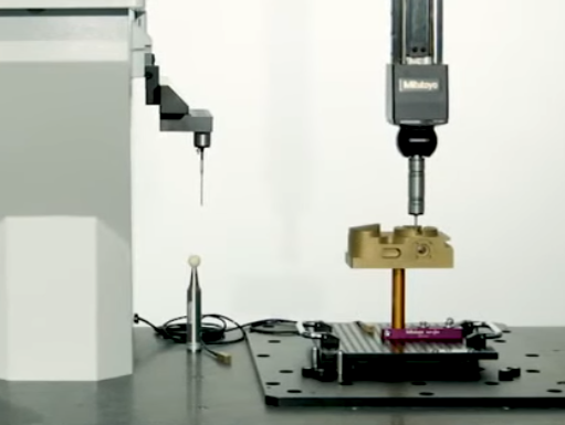
| Micrometers (outside/inside) | Resolution 0.001 mm; accuracy ±0.002 mm to ±0.004 mm | Critical diameters, thickness, precision lengths |
| Height gauges and surface plates | Resolution 0.001 mm (digital); accuracy depending on grade | Height, step measurements, layout inspection |
| Gauge blocks and ring/plug gauges | Sub-micron reference accuracy | Calibration, go/no-go acceptance of critical features |
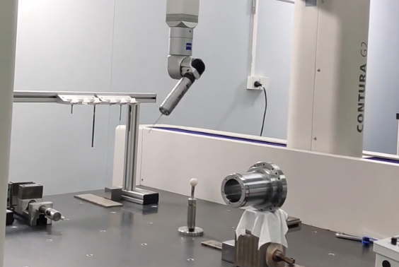
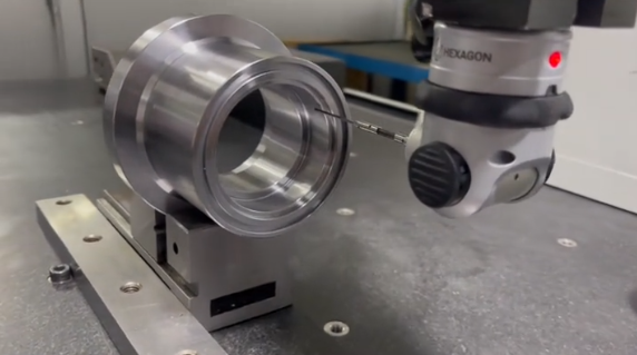
| CMM (coordinate measuring machine) | Typical volumetric accuracy (MPEe) from 1.5 µm + L/350 to 3.5 µm + L/250 | Complex geometry, position tolerances, 3D profiles |
| Optical measuring systems | Resolution to 0.5 µm or better | Small parts, 2D profiles, non-contact measurement |
| Surface roughness testers (profilometers) | Ra measurement typically from 0.005 µm to 40 µm | Surface finish verification |
| Hardness testers (Rockwell, Vickers, Brinell) | Accuracy in hardness units per instrument standard | Material condition and heat-treatment verification |
Calibration and Measurement System Capability
Measurement results must be reliable and traceable. A quality-controlled CNC environment maintains a calibration system aligned with national or international standards (for example, ISO/IEC 17025 accredited laboratories).
Key practices include:
- Periodic calibration of instruments according to manufacturer recommendations and internal procedures.
- Use of traceable reference standards (gauge blocks, ring gauges, artifacts).
- Environmental control during measurement, especially for tight tolerances (temperature around 20 °C, limited temperature gradient, controlled humidity).
- Measurement System Analysis (MSA) to evaluate repeatability and reproducibility (R&R).
MSA ensures that measurement variation is significantly smaller than the tolerance width. A typical target is to have total gauge R&R less than 10% of the tolerance; between 10% and 30% may be conditionally acceptable depending on application.
Inspection Types in CNC Machining
CNC quality control typically uses a structured sequence of inspections designed to detect issues as close as possible to the point of origin.
First Article Inspection (FAI)
First Article Inspection verifies that the manufacturing process using given machines, setups, tools, and programs can produce a part conforming to requirements. It is usually performed for the first part of a new product, revision, or process configuration.
Characteristics of FAI:
- Full dimensional inspection or at least all drawing dimensions marked by customer.
- Verification of materials, certificates, and special processes (for example, heat treatment, coating).
- Use of approved forms and documentation (e.g., AS9102 in aerospace).
- Approval required before serial production.
In-Process Inspection
In-process inspection monitors key dimensions and characteristics during machining. Its purpose is to keep the process centered and detect drift before parts fall out of tolerance.
Common practices include:
- First-off inspection at each setup, tool change, or shift start.
- Periodic measurement of CTQ features based on time, quantity, or tool wear expectations.
- Use of machine probing to perform automatic in-cycle checks and tool wear compensation.
- Go/no-go gauges for quick verification of holes and shafts.
Final Inspection
Final inspection confirms that completed parts meet all requirements prior to shipment or assembly. The scope can vary from sampling to 100% inspection depending on product criticality, customer agreements, and process capability.
Activities typically include:
- Verification of all characteristics required by control plan or customer.
- Visual inspection for appearance, burrs, contamination, and marking.
- Review of documentation, certificates, and traceability records.
- Application of marking, labeling, and packaging requirements.
Process Capability and Statistical Process Control
Stable, capable processes are the foundation of predictable CNC quality. Process capability quantifies how well a machining process can produce parts within specified tolerances when in statistical control.
Key indices include:
- Cp: process potential capability, compares tolerance width to process spread (6σ).
- Cpk: process capability considering centering relative to specification limits.
- Pp and Ppk: similar to Cp and Cpk but based on overall (long-term) variation.
Typical capability targets for critical features often require Cpk ≥ 1.33 or higher for serial production, with more stringent applications requiring Cpk ≥ 1.67 or higher.
Statistical Process Control (SPC) uses control charts (for example, X̄–R, X̄–S, individual-X) to monitor variations over time. When charts indicate special-cause variation, corrective actions are taken on the machining process (tooling, fixturing, setup, cutting conditions) rather than simply adjusting offsets based on single measurements.
Materials, Heat Treatment and Hardness Verification
Material and heat-treatment condition strongly influence machinability and final part performance. CNC quality control verifies that the correct material is used and that mechanical properties meet specified requirements.
Key aspects include:
- Incoming inspection of material certificates (chemical composition, mechanical properties, standards).
- Positive material identification (PMI) when required (for example, spectrometer for alloys).
- Verification of hardness using Rockwell, Vickers, or Brinell tests according to standards.
- Dimensional checks after heat treatment to account for distortion and size change.
Results from heat treatment and hardness tests are recorded and linked to part batches via traceability identifiers such as heat numbers, batch numbers, or serial numbers.
Tooling, Fixtures, and Machine Condition
CNC quality is closely related to the condition of cutting tools, fixtures, and machines. Quality control procedures must also cover equipment condition and maintenance.
Elements to monitor include:
- Tool life and wear limits defined for each operation, with scheduled tool changes or in-process wear measurement.
- Tool presetting and length/diameter measurement accuracy.
- Fixture geometry, rigidity, and repeatability, particularly for multi-setup parts.
- Machine accuracy and repeatability, including linear and rotary axes error compensation where applicable.
Periodic machine capability studies using reference artifacts (such as ball bars or step gauges) help ensure the machine can consistently maintain the required tolerances.
Programming, Setup and Verification Procedures
CAM programming and machine setup directly impact the dimensional and geometric quality of CNC parts. Quality control addresses these activities via standardized procedures and checks.
Key measures include:
- Verification of CAM toolpaths against CAD models to avoid overcuts and gouging.
- Use of simulation and collision detection to prevent crashes and unintended tool-part interactions.
- Documented setup sheets specifying datums, fixtures, tool lists, offsets, and key inspection dimensions.
- Controlled program revision management with approved release and change records.
Clear communication between engineering, programming, and shop floor personnel minimizes discrepancies between design intent and realized parts.

Documentation, Traceability and Record Keeping
Documentation provides evidence of conformity, supports traceability, and enables analysis for process improvement. A structured document and record system is central to CNC quality control.
Typical documentation includes:
- Control plans detailing what to measure, how, how often, and with what criteria.
- Inspection procedures and work instructions for operators and inspectors.
- Calibration records for measurement equipment.
- Inspection reports (in-process, FAI, final) including measurement data and acceptance decisions.
- Nonconformance reports, rework instructions, and concession/deviation records when applicable.
Traceability links include part numbers, revision levels, batch or lot numbers, machine IDs, operator IDs, and timestamps. For regulated industries, retention times and formats may be specified by standards or legislation.
Common Quality Issues in CNC Machining
Despite robust procedures, CNC operations often encounter recurring quality issues that need systematic control.
Typical problem areas include:
- Dimensional drift due to tool wear, thermal growth, or fixture movement.
- Positional errors on multi-axis parts when datum definition and work offset management are inconsistent.
- Surface defects such as chatter marks, burrs, and scratches introduced during machining or handling.
- Incorrect application of GD&T resulting in misinterpretation of acceptance criteria.
- Variation between measuring devices (for example, operator calipers vs. CMM results) due to measurement system differences.
Addressing these issues often requires coordinated actions involving process engineering, maintenance, programming, and quality specialists, supported by data from inspections and SPC.
Integration with Quality Management Systems
CNC quality control usually operates within a broader quality management system such as ISO 9001 or sector-specific frameworks (for example, IATF 16949, AS9100, ISO 13485). These systems require documented processes, risk-based thinking, and evidence of control.
In this context, CNC quality control contributes by:
- Providing documented procedures for inspection and testing.
- Demonstrating control of nonconforming product through defined dispositions (rework, repair, scrap, use-as-is with concession).
- Supporting internal audits with records and evidence of compliance.
- Supplying quality metrics such as internal defect rates, scrap levels, and customer return data.
Best Practices for Stable CNC Quality
Consistently high-quality CNC machining relies on a combination of technical and organizational practices.
Effective measures include:
- Early involvement of manufacturing and quality engineers during design, to ensure tolerances and surfaces are achievable and measurable.
- Clear identification and prioritization of critical characteristics with appropriate control methods.
- Robust work instructions for setups, operation, and inspection, including visual aids and examples.
- Use of statistical tools to monitor and maintain process capability for important features.
- Regular training for operators and inspectors on measurement techniques, GD&T interpretation, and use of inspection equipment.
FAQ About CNC Quality Control
What is CNC quality control?
CNC quality control refers to the processes and inspections used to ensure that CNC-machined parts meet specified dimensional, material, and performance requirements throughout production.
What inspection methods are used for CNC parts?
Common inspection methods include:
Coordinate Measuring Machines (CMM)
Calipers and micrometers
Height gauges
Surface roughness testers
Visual and functional inspections
Do you perform first article inspection (FAI)?
Yes. First Article Inspection is conducted before full production to verify dimensions, tolerances, and material specifications according to customer drawings and standards.
What is the difference between inspection and process control in CNC machining?
Inspection checks parts against specifications at defined points (for example, first article, in-process, final) to decide acceptance or rejection. Process control focuses on maintaining the machining process itself within stable limits using methods such as SPC, machine capability studies, and tool life management. Inspection provides data, while process control uses this data to adjust setups, tooling, and parameters so that parts consistently stay within specifications.
When should a CNC shop use a CMM for quality control?
A CMM is suitable when parts have complex 3D geometries, tight positional tolerances, or profiles that are difficult to measure with handheld tools. It is also needed when customers require detailed dimensional reports or when tolerances approach the limits of manual measuring equipment. For simpler parts with moderate tolerances, gauges, calipers, and micrometers may be sufficient, but for complex or high-accuracy components, a CMM significantly increases measurement reliability and repeatability.
