
CNC surface finish is a critical characteristic of machined parts that directly affects assembly, sealing, wear, fatigue strength, appearance, coating adhesion, and functional performance. Understanding how to specify, achieve, measure, and control surface finish is essential in CNC design, process planning, and production.
Fundamentals of CNC Surface Finish
CNC surface finish describes the small-scale texture left on a part after machining or post-processing. It is mainly determined by tool geometry, cutting conditions, workpiece material, machine tool performance, and subsequent finishing operations.
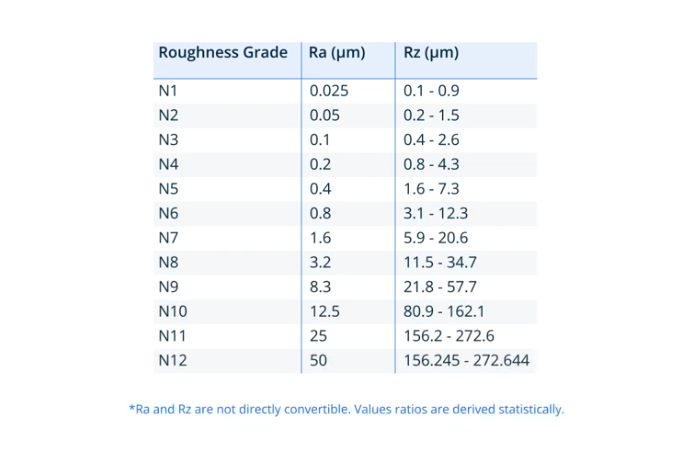
In engineering practice, surface finish is usually quantified by roughness parameters such as Ra or Rz, defined by international standards (ISO 4287/4288, ASME B46.1, etc.). These parameters provide a numeric basis to compare processes, specify drawing requirements, and control quality.
Key Surface Roughness Parameters
Many parameters exist, but a few are commonly used in CNC part drawings and quality control. They describe the amplitude, spacing, and shape of the microscopic profile deviations from an ideal surface.
Ra – Arithmetic Average Roughness
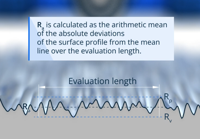
Ra (arithmetical mean deviation of the assessed profile) is the most widely used surface roughness parameter. It is the arithmetic average of the absolute values of the profile height deviations from the mean line over a specified evaluation length.
Ra provides a single-value indicator of overall roughness amplitude. It is simple to measure and compare, which explains its prevalence in CNC machining drawings and specifications.
Rz – Mean Peak-to-Valley Height
Rz (mean roughness depth) is the average vertical distance between the highest peak and lowest valley in several sampling lengths. Compared to Ra, Rz is more sensitive to isolated peaks or defects, which can be important in sealing surfaces, contact surfaces, and fatigue-critical regions.
Common Roughness Levels by Process
Typical ranges of Ra achievable by common CNC-related processes are shown below. Actual values depend on material, machine condition, tooling, and parameters.
| Process | Typical Ra Range (µm) | Notes |
|---|---|---|
| Rough turning / facing | 3.2 – 12.5 | High material removal, low focus on finish |
| Semi-finish turning | 1.6 – 3.2 | Balanced removal and finish |
| Finish turning | 0.4 – 1.6 | Smaller depth of cut, optimized feed |
| Rough milling | 3.2 – 12.5 | High feed and step-over |
| Finish milling | 0.8 – 3.2 | Reduced feed and step-over; sharp tool |
| Precision grinding | 0.1 – 0.4 | High consistency and tight control |
| Superfinishing / lapping | 0.01 – 0.1 | Very fine finishes for critical surfaces |
| Hand polishing | 0.05 – 0.4 | Dependent on operator and abrasives |
Surface Finish Requirements in Engineering Design
Surface finish requirements must be aligned with functional needs, cost targets, and manufacturability. Overly tight surface finish specifications can significantly increase cycle time, tooling costs, inspection demands, and scrap rates.
Functional Considerations
- Sealing surfaces often require lower roughness to minimize leakage paths and improve gasket performance.
- Sliding surfaces may need controlled roughness to balance friction, lubrication retention, and wear.
- Fatigue-critical areas can benefit from smoother finishes to reduce stress concentration at surface irregularities.
- Decorative surfaces demand uniform and visually pleasing textures, often requiring secondary finishing such as polishing or bead blasting.
Drawing Callouts and Symbols
Engineering drawings typically use standardized surface finish symbols to communicate requirements. Common elements include:
- Roughness parameter and value (e.g., Ra 1.6 µm).
- Machining allowance or removal requirement symbols where needed.
- Direction of lay indication when anisotropic texture matters for performance, such as sealing or sliding.
Balancing Performance and Cost
Specifying surface finish values lower than necessary may lead to unnecessary operations like extra passes, grinding, or polishing. Proper communication between designers and manufacturing engineers is essential to identify the minimum surface finish that fulfills functional requirements while controlling cost and lead time.
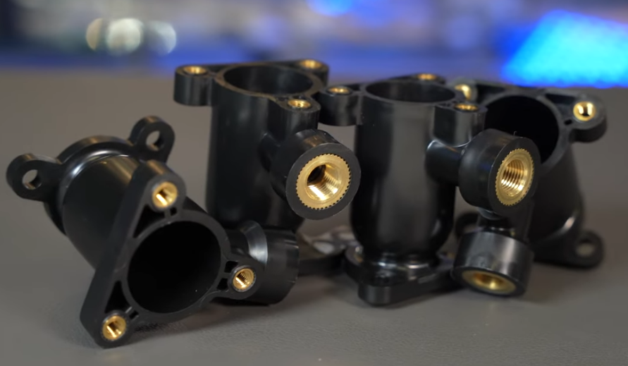
Primary CNC Machining Processes and Surface Finish Characteristics
Different CNC processes produce different surface textures. The cutting mechanics, tool geometry, and kinematics produce characteristic lay patterns and roughness ranges.
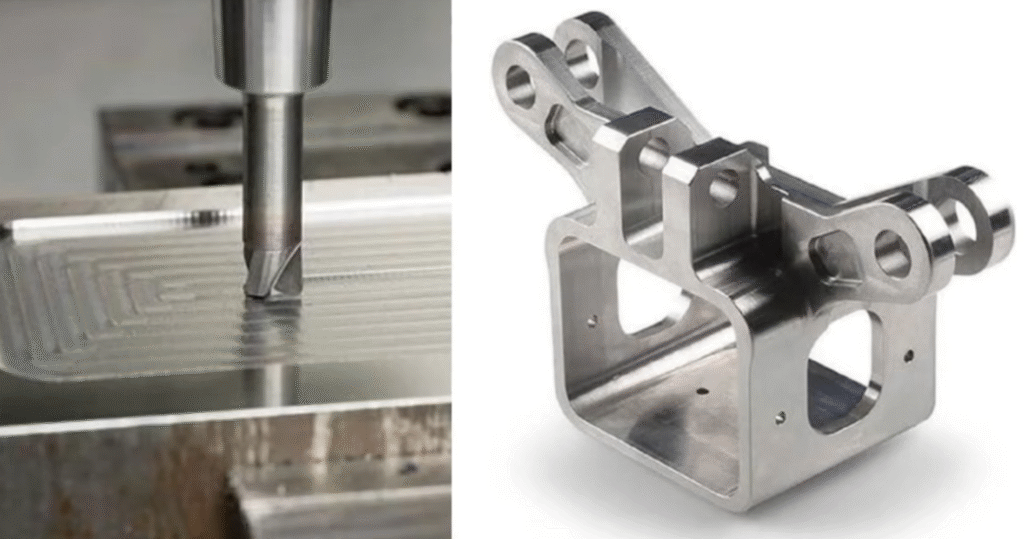
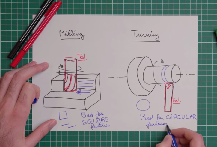
CNC Turning
CNC turning generates surfaces by the rotational motion of the workpiece combined with linear or curvilinear motion of the cutting tool. Surface texture is primarily defined by feed rate, nose radius, tool condition, and material.
Key aspects affecting finish in turning include:
- Smaller feed rates generally reduce surface roughness but increase cycle time.
- Larger tool nose radii can reduce roughness but may increase cutting forces and risk of chatter.
- Stable clamping and minimized runout are essential to avoid pattern irregularities and vibration marks.
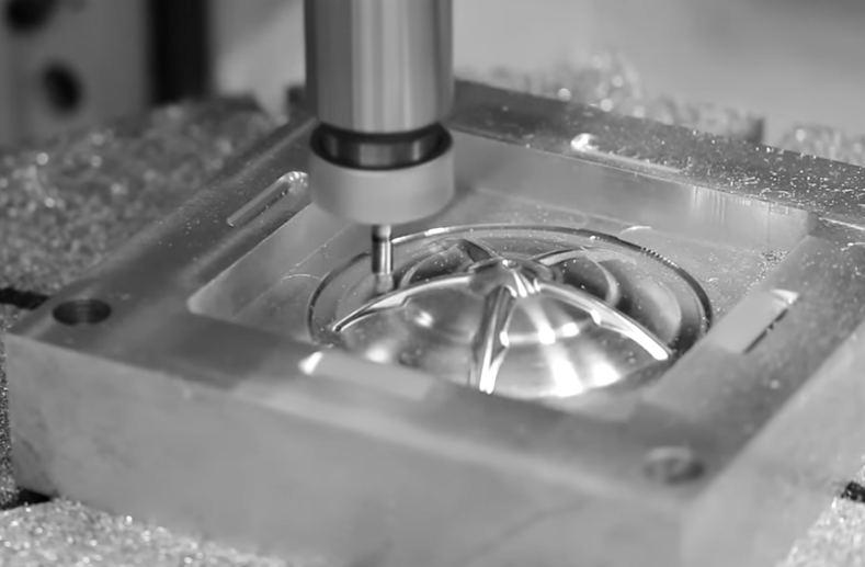
CNC Milling
CNC milling creates surfaces through the rotational cutting action of multi-edge tools combined with feed motion of the workpiece or tool. The resulting finish is influenced by feed per tooth, step-over (radial engagement), axial depth of cut, tool path strategy, and spindle speed.
Typical characteristics:
For flat surfaces, scallop height depends on step-over and tool diameter; reducing step-over usually improves finish. For contoured 3D surfaces, toolpath smoothing, small step-down and step-over, and optimized cutter orientation are used to obtain fine finishes.
CNC Grinding
Grinding uses abrasive wheels with numerous cutting edges and is often applied after turning or milling when improved dimensional accuracy and much finer surface finishes are needed. It provides high repeatability and consistent roughness in low Ra ranges.
Parameters affecting finish include wheel grit size, wheel hardness, dressing condition, infeed, work speed, and coolant application. Proper wheel selection and dressing are essential to avoid burns, chatter, or excessive roughness.
CNC Drilling, Reaming, and Boring
Internal surfaces such as holes, bores, and seats have specific finish requirements for press fits, sliding fits, and sealing. Drilling alone typically yields moderate finishes; reaming and boring can significantly improve surface quality and dimensional accuracy.
Controlled reaming often produces better Ra values than drilling, while fine boring with optimized inserts can approach finish turning quality on internal surfaces.
Post-Machining Finishing Processes
After CNC machining, additional finishing processes are often applied to achieve required roughness, surface integrity, and aesthetics.
Abrasive Finishing
Abrasive finishing includes grinding, honing, lapping, and superfinishing. These processes use bonded or loose abrasives to gradually remove high spots and refine surface texture.
Honing improves cylinder bores and similar shapes, generating a cross-hatch pattern beneficial for lubricant retention. Lapping and superfinishing can reduce Ra to the nanometer scale for precision components such as seals, bearing races, and optical surfaces.
Mechanical Finishing
Mechanical finishing processes, such as tumbling, vibratory finishing, shot peening, and bead blasting, can modify surface characteristics by impacting or rubbing media against the part.
Bead blasting produces a uniform matte texture and can mask minor machining marks. Shot peening creates compressive residual stresses and can improve fatigue life, while slightly modifying surface roughness.
Polishing and Buffing
Polishing uses progressively finer abrasives on wheels or pads to smooth surfaces. Buffing refines the surface further using soft wheels and compounds, often to achieve a mirror-like appearance on metals.
These processes are common in applications where appearance, low friction, or hygiene are critical, such as consumer products, medical instruments, and food-contact components.
Chemical and Electrochemical Finishing
Chemical and electrochemical processes can both modify surface appearance and influence functional performance.
Examples include:
- Chemical polishing, which smooths microscopic peaks through controlled chemical dissolution.
- Electropolishing, commonly used for stainless steel, which preferentially removes high points and enhances corrosion resistance and cleanliness.
- Passivation, which mainly improves corrosion resistance while slightly affecting surface texture on a microscopic level.
Surface Finish and Material Types
Material properties significantly influence attainable surface finish, tool life, and the choice of process parameters. Different materials require specific tool geometries, coatings, and cutting conditions to achieve desired roughness.
Aluminum and Aluminum Alloys
Aluminum is relatively soft and easy to machine, allowing low roughness values at high cutting speeds. However, it can smear or form built-up edge on tools, which may degrade finish.
Sharp tools, high positive rake angles, suitable tool coatings, and effective chip evacuation help maintain a bright, fine finish. For decorative or aerospace components, anodizing is often combined with controlled machining finish to achieve both appearance and corrosion resistance.
Carbon and Alloy Steels
Steels cover a wide hardness range. Low-carbon steels are generally easy to machine but may show tearing under certain conditions, affecting surface quality. Hardened steels require optimized tooling and often grinding or superfinishing to achieve fine finishes.
Coolant selection, stable clamping, and appropriate tool geometry help prevent built-up edge, chatter, and surface defects such as micro-cracks or burn marks.
Stainless Steels
Stainless steels tend to be more challenging to machine due to work hardening, lower thermal conductivity, and higher toughness. These properties can produce higher cutting temperatures, accelerated tool wear, and surface integrity issues.
To achieve suitable finishes, cutting conditions are often more conservative, with stable feeds, sharp tools, and effective cooling. In many applications, electropolishing or mechanical polishing is used after CNC machining to refine the surface and improve corrosion performance.
Titanium and High-Temperature Alloys
Materials such as titanium and nickel-based superalloys are sensitive to heat and work hardening and tend to produce difficult-to-cut chips. Achieving fine finishes requires rigid setups, controlled low to moderate cutting speeds, and high-quality coated tools.
Post-machining processes, including grinding, polishing, and controlled chemical treatments, may be used in aerospace and medical components where both finish and integrity are critical.
Plastics and Composites
Plastics can produce very smooth surfaces but are prone to melting, smearing, and burr formation if machining parameters are not optimized. Tool geometry with high rake and sharp edges, along with controlled cutting speeds and chip evacuation, helps to maintain good finish.
Fiber-reinforced composites often require specialized tools and methods to minimize delamination, fiber pull-out, and surface damage. Achieving smooth finishes may involve fine milling, grinding, or sealing with coatings or resins.
Process Parameters Influencing CNC Surface Finish
Surface finish can often be optimized through parameter selection without changing the basic process. Understanding the relationship between parameters and resulting roughness helps in process planning and troubleshooting.
Cutting Speed (Spindle Speed)
Cutting speed affects cutting forces, chip formation, and temperature. For many materials, increasing cutting speed within a suitable range can improve finish by reducing built-up edge and smoothing the cutting action. Excessive speeds, however, may cause tool wear, chatter, or thermal damage that degrades surface quality.
Feed Rate
Feed rate is one of the most direct influences on surface roughness. Higher feed rates increase the distance between successive tool marks, generating a more pronounced surface pattern. Lower feed rates usually improve finish but increase machining time and may cause rubbing if too low.
Depth of Cut and Radial Engagement
Depth of cut affects cutting forces and stiffness of the system. In finishing operations, smaller depths of cut reduce cutting forces and enable smoother surfaces. In milling, radial engagement and step-over determine scallop height and pattern, especially in 3D contouring.
Tool Geometry and Nose Radius
Tool nose radius strongly influences surface finish. A larger nose radius can produce smoother surfaces by reducing the height of feed marks, but it also increases radial cutting forces. Proper selection is a balance between finish targets, part geometry, and machine rigidity.
Rake angle, clearance angle, and edge preparation also affect chip flow and cutting pressure, which in turn influence roughness, burr formation, and surface integrity.
Tool Condition and Coating
Tool wear directly impacts surface finish. Flank wear, crater wear, chipping, or built-up edge can lead to irregular patterns, tearing, and rough surfaces. Regular tool inspection and timely replacement are essential for consistent finishes.
Tool coatings can reduce friction, control temperature, and improve chip evacuation. This often helps achieve better and more stable surface finishes, especially in difficult-to-machine materials.
Machine Tool Rigidity and Vibration
Machine stiffness, spindle condition, and fixture rigidity strongly affect surface finish. Vibration and chatter create periodic patterns and wave marks that can significantly increase roughness and compromise function.
Good practices include using rigid tooling and holders, minimizing tool overhang, optimizing cutting conditions relative to machine dynamics, and ensuring robust workholding.
Coolant and Lubrication
Proper coolant selection and delivery help reduce heat, flush chips, and lubricate the cutting zone. This can prevent built-up edge and surface burn while improving finish. In high-speed dry machining, air blast or minimum quantity lubrication is often used to control chip evacuation and temperature.
Surface Integrity Beyond Roughness
Surface finish is not only about geometric roughness. Surface integrity includes metallurgical and mechanical conditions such as residual stresses, microstructure, hardness, and the presence of microcracks or deformation layers.
Residual Stresses
Machining can produce tensile or compressive residual stresses at the surface. Tensile residual stresses may reduce fatigue strength, while compressive stresses can be beneficial. Grinding burns, for example, can introduce harmful tensile stresses and microcracks even if roughness values appear acceptable.
Work Hardening and Microstructure
Some materials undergo work hardening at the surface due to severe plastic deformation during cutting. This affects wear behavior, friction, and fatigue performance. Process parameters and tool geometry should be chosen to avoid excessive work hardening where detrimental.
Surface Defects
Typical surface defects include chatter marks, tearing, laps, built-up edge deposits, burns, and smeared material. These defects can be more critical than the roughness value itself, particularly in sealing, high-speed rotating, or fatigue-loaded components.

Inspection Methods for CNC Surface Finish
Surface finish inspection ensures that parts meet drawing requirements and functional needs. The choice of measurement method depends on required accuracy, part geometry, and production volume.
Contact Profilometers
Contact stylus profilometers use a diamond-tipped stylus that traverses the surface, recording the vertical deviations to compute Ra, Rz, and other parameters. They are widely used due to their reliability, standardization, and relatively straightforward operation.
Care must be taken to select proper cutoff length, stylus radius, and measurement direction relative to lay to obtain meaningful results.
Non-Contact Optical Methods
Optical measurement techniques, such as white light interferometry, confocal microscopy, and focus variation, enable high-resolution 3D surface characterization without physical contact. They are useful for soft materials, delicate features, and detailed analysis of complex topographies.
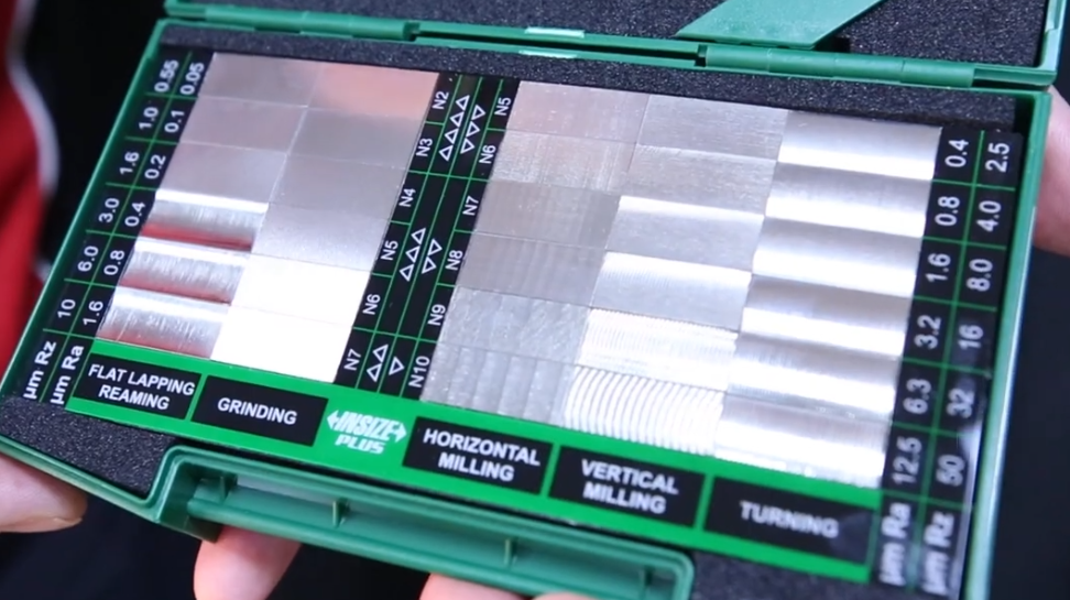
Comparators and Visual Evaluation
Surface finish comparators and visual inspection are often used in shop environments for quick assessments. Machinists compare the machined surface with calibrated standard specimens or reference charts to get an approximate roughness. This method is less precise but valuable for rapid checks and process monitoring.
Sampling Strategy and Orientation
Effective inspection requires proper selection of measurement locations, sampling lengths, and orientation relative to surface lay. For critical functional surfaces, multiple measurements may be necessary to capture variability across the part.
Typical Application Requirements and Finish Selection
Different applications demand different levels of surface finish. It is important to match realistic roughness values to functional needs and process capabilities.
| Application / Feature | Typical Ra (µm) | Notes |
|---|---|---|
| General structural surfaces | 3.2 – 6.3 | Non-critical appearance and fit |
| Standard bearing seats | 0.8 – 1.6 | Good balance of cost and performance |
| Sealing surfaces (O-ring grooves) | 0.4 – 1.6 | Avoid sharp peaks and scratches |
| Hydraulic cylinder bores | 0.1 – 0.4 | Honed cross-hatch for lubrication |
| Press-fit mating surfaces | 0.8 – 3.2 | Depends on interference and material |
| Decorative visible surfaces | 0.2 – 1.6 | Often followed by polishing or coating |
| High-precision spindle components | 0.02 – 0.1 | Requires grinding or superfinishing |
Process Planning for Desired CNC Surface Finish
Achieving specified finishes consistently requires integrated planning from design to production. This involves selecting appropriate machine tools, cutting strategies, and inspection methods based on the surfaces to be produced.
Roughing, Semi-Finishing, and Finishing Stages
A common approach is to divide machining into roughing, semi-finishing, and finishing stages:
Roughing removes the majority of material with high feeds and depths, prioritizing efficiency. Semi-finishing corrects distortion from roughing and prepares uniform stock for finishing. Finishing uses optimized parameters and tools to achieve final tolerance and surface quality.
Toolpath Strategies
In CNC milling, toolpath strategy has a major effect on surface finish. Constant scallop toolpaths, high-speed machining strategies with smooth transitions, and appropriate step-over and step-down settings are used to produce uniform finishes and avoid marks from direction changes.
In turning, constant surface speed and optimized transition between passes reduce visible steps and irregularities.
Tool Selection and Management
Choosing tool material, coating, geometry, and holder type is integral to finishing performance. Dedicated finishing tools with specific nose radii and edge preparations are often used separate from roughing tools.
Tool life management and tool wear monitoring are essential to avoid degradation in finish quality over time, especially in high-volume production.
Workholding and Setup
Secure and rigid workholding prevents micro-movements that lead to chatter and uneven surfaces. For thin-walled or slender parts, specialized fixtures, support devices, and optimized cutting forces help maintain both dimensional accuracy and surface quality.

Surface Finish Issues and Troubleshooting Considerations
When surface finish deviates from requirements, root cause analysis should consider the interaction between tool, machine, material, and parameters. Addressing the correct factor is essential to avoid repeated iterations.
Common Surface Finish Issues
Typical issues include:
- Visible chatter marks or periodic patterns due to vibration or instability.
- High roughness values caused by excessive feed, tool wear, or improper nose radius.
- Built-up edge causing tearing, smeared metal, and uneven texture.
- Burns or discoloration indicating excessive heat or insufficient coolant.
- Burrs at edges due to improper cutting conditions or tool geometry.
Systematic Adjustment Approach
A structured troubleshooting approach may include:
First, verifying tool condition and ensuring it is sharp and correctly installed. Then, adjusting feed, speed, and depth of cut within recommended ranges to balance forces and temperature. Next, improving workholding rigidity and checking machine mechanical condition. Finally, considering alternative tools, coatings, or finishing processes if required finish is beyond current capability.
Surface Finish and Coatings
Surface finish strongly affects how coatings and surface treatments behave, both in terms of adhesion and visual appearance. Pre-coating roughness specifications are often defined to ensure coating performance.
Anodizing
For aluminum parts, anodizing thickness and type interact with underlying roughness. Rougher surfaces can lead to matte or uneven appearance, while smoother surfaces produce more uniform and glossy results. Pre-anodizing finish is typically controlled through fine machining, polishing, or bead blasting.
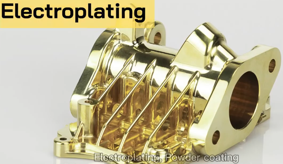
Plating and PVD/CVD Coatings
Electroplating, electroless plating, and physical or chemical vapor deposition replicate and sometimes slightly smooth underlying microgeometry. If the substrate is too rough, the coating may not hide defects and may even amplify them visually.
Specifying suitable pre-coating roughness and using compatible finishing processes ensure coating adhesion and desired appearance.
Paint and Powder Coating
Paint and powder coatings can partially level small surface features, but significant tool marks or roughness remain be visible. Pre-treatment may involve sanding, blasting, or fine machining to get a uniform base surface.
Documentation and Traceability of Surface Finish
For critical components, documenting and tracking surface finish characteristics is part of quality management. This includes recording measurement results, inspection locations, instruments used, and process parameters.
Inspection Records
Inspection records support product acceptance, process validation, and traceability. They may include numerical roughness values, measurement setup conditions, and comparison against drawing requirements.
Process Control Documentation
Process control documentation may define standard parameter windows, tool types, inspection frequency, and acceptance criteria. This enables operators and engineers to maintain stable and repeatable surface finishes across batches.
FAQ About CNC Surface Finish
What is CNC surface finish?
CNC surface finish refers to the texture and smoothness of a machined part’s surface after CNC machining. It is usually measured by surface roughness values such as Ra or Rz.
Why is surface finish important in CNC machining?
Surface finish affects the appearance, performance, friction, wear resistance, and fit of CNC parts. A better surface finish can improve durability and functionality.
What surface finishes can be achieved with CNC machining?
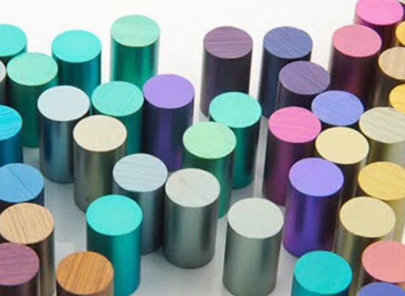
Common CNC surface finishes include as-machined, bead blasted, polished, brushed, anodized, powder coated, and plated finishes, depending on material and application.
What is the standard surface roughness for CNC machining?
The typical as-machined surface roughness is around Ra 3.2 μm (125 μin). Finer finishes such as Ra 1.6 μm or Ra 0.8 μm can be achieved with additional processing.
Does surface finish affect CNC machining cost?
Yes. Tighter surface finish requirements usually increase machining time and cost due to slower cutting speeds and additional finishing operations.
