

Accurate measurement of CNC parts is essential for verifying dimensional conformity, ensuring assembly fit, and maintaining stable process capability. This guide explains how to interpret requirements, select inspection tools, set up measurements, control errors, and document results in a structured, practical way.
About Measurement Requirements for CNC Parts
Before choosing instruments or planning inspection, the requirements must be clearly understood and translated into measurable characteristics. This starts from the technical documentation and flows down to specific inspection actions.
Drawing and Specification Interpretation
Measurement requirements are typically defined in engineering drawings, 3D models with PMI (Product Manufacturing Information), and accompanying specifications. Key elements include:
- Nominal dimensions and tolerances (e.g., 25.00 ±0.02 mm)
- Geometric Dimensioning and Tolerancing (GD&T) callouts (e.g., flatness, position, runout)
- Surface texture specifications (e.g., Ra ≤ 1.6 µm)
- Material and heat treatment that may affect size and deformation
Each requirement should be translated into a measurable quantity: length, diameter, angle, flatness, perpendicularity, runout, profile, or surface parameter.
Critical Versus Non‑Critical Features
Not all dimensions have equal importance. For effective measurement planning, features are classified as:
Functional/critical features — direct impact on fit, sealing, alignment, or safety. These often have tighter tolerances and may need higher‑precision instruments, more measurements per batch, and additional traceability.
Non‑critical features — cosmetic or non‑functional areas with looser tolerances and simpler measurement methods.
Types of Measurement Tasks
Common CNC part verification tasks include:
- Dimensional measurement (lengths, diameters, thicknesses, distances, angles, radii)
- Geometric measurement (form, orientation, position, runout, profile using GD&T)
- Surface measurement (roughness, waviness, lay direction)
- Thread and gear measurement (pitch, flank angle, lead, tooth profile)
Each task has different instrument requirements, measurement strategies, and uncertainty levels.
Key Metrology Concepts for CNC Part Measurement
Accurate measurement relies on understanding key metrology concepts that determine the reliability of results.
Accuracy, Precision, and Resolution
These three parameters describe instrument and process capability:
| Parameter | Typical Meaning | Example Impact on CNC Measurement |
|---|---|---|
| Accuracy | Closeness of measurement to the true value | If a 50.000 mm gage block is measured as 50.015 mm, the system accuracy is off by 0.015 mm |
| Precision (repeatability) | Closeness of repeated measurements to each other | Five measurements of the same feature showing 50.002–50.003 mm indicates good precision |
| Resolution | Smallest change in value that the instrument can display | A micrometer with 0.001 mm resolution can show smaller differences than one with 0.01 mm resolution |
A common guideline is that measurement system resolution should be at least 10 times finer than the tolerance width (10:1 rule). For example, a tolerance of ±0.02 mm (total width 0.04 mm) ideally uses an instrument with 0.001–0.002 mm resolution.
Measurement Uncertainty
Every measurement has uncertainty due to instrument limitations, environmental influence, operator technique, and part variability. For production inspection, uncertainty is controlled implicitly by:
- Using instruments with adequate accuracy compared to tolerance
- Regular calibration against traceable standards
- Consistent measurement procedures
For critical parts, formal uncertainty analysis may be required, where combined effects of each source (instrument, temperature, fixturing, alignment) are quantified.
Traceability and Calibration
To ensure comparability over time and across facilities, measurement results must be traceable to national or international standards. This is achieved via:
- Calibrated gage blocks, rings, plugs, step gages, and master parts
- Calibration certificates with stated uncertainty and validity period
- Instrument labeling and records for due calibration dates
Without traceability, even highly precise readings may not be accepted in regulated or customer‑audited environments.
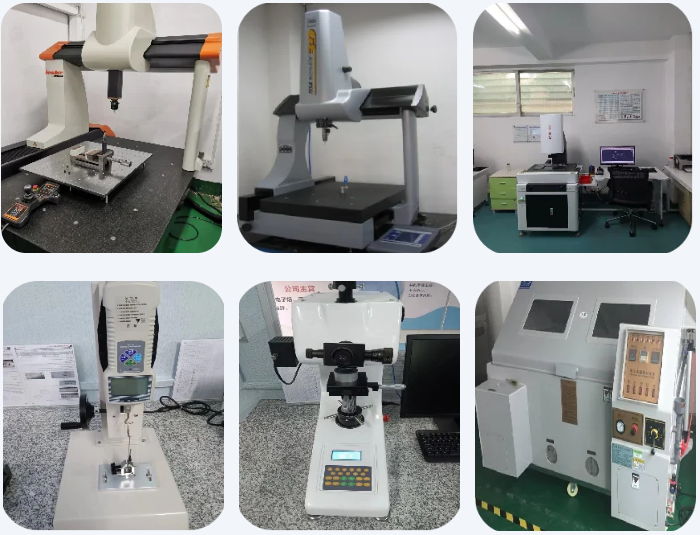
Selecting the Right Instruments for CNC Parts
Instrument selection depends on required accuracy, geometry, accessibility, and production volume. Choosing inappropriate tools is a common cause of measurement deviation and inspection bottlenecks.
Hand Tools: Calipers and Micrometers
Calipers (digital, dial, or vernier) are versatile and fast but have limited accuracy compared to micrometers. Typical characteristics:
- Typical resolution: 0.01 mm (some models 0.005 mm)
- Typical accuracy: ±0.02 mm over the first 100 mm
They are suitable for general dimensions with tolerances ≥ ±0.05 mm, but less appropriate for very tight tolerances.
Micrometers provide higher precision for external, internal, and depth measurements:
- Resolution commonly 0.001 mm (0.00005 in)
- Accuracy often around ±0.002 mm to ±0.004 mm depending on range
They are suitable for tight tolerances such as ±0.01 mm or better, assuming proper technique and temperature control.
Height Gages and Surface Plates
Height gages used with a granite surface plate allow accurate measurement of heights, distances, and hole locations in 2D. Key points:
- Surface plate flatness typically within a few micrometers over working area
- Digital height gages often have 0.001 mm or 0.005 mm resolution
These setups are effective for checking vertical dimensions, relative heights, and simple geometric relationships, particularly in inspection rooms.
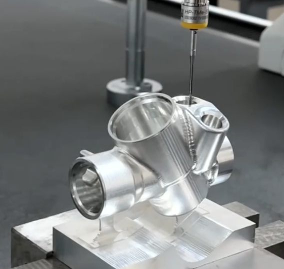
Coordinate Measuring Machines (CMM)
CMMs allow highly accurate, repeatable measurement of complex geometries, including GD&T features. Key parameters:
- Typical volumetric accuracy: from about (1.5 + L/300) µm to (5 + L/200) µm, where L is measured length in mm
- Trigger probe repeatability often within 0.5–1.5 µm
CMMs are ideal for:
- Complex prismatic parts with multiple datums and features
- Positional tolerances, profiles, and compound geometries
- Measurement of parts requiring automated report generation
They require stable environment control, periodic calibration, and proper fixturing to leverage their accuracy.
Optical and Vision Systems
Optical comparators and vision measuring systems are useful for small, delicate, or complex profile features that are hard to access mechanically. They are especially effective for:
- 2D profile measurement: contours, radii, chamfers, slots
- Thin parts: stamped components, small machined plates
- High‑magnification inspection of burrs and edge conditions
Typical resolution can be as fine as a few micrometers; accuracy depends on magnification, field of view, and calibration.
Specialized Gages and Plug/Ring Gages
For high‑volume production, fixed gages offer fast, go/no‑go decisions with simple operation:
- Plug gages for internal diameters
- Ring gages for external diameters
- Thread plug and ring gages for thread conformity
- Functional gages built to combined tolerances (e.g., for hole patterns)
These tools are calibrated to precise limits and used frequently at the machine for in‑process checks.
Surface Roughness Testers
When surface finish requirements are specified (e.g., Ra, Rz), a surface roughness tester is needed. Stylus‑type instruments are common in CNC environments:
- Cut‑off length and sampling length selectable according to standard (e.g., ISO 4287, ISO 4288)
- Measurement parameters display Ra, Rz, Rq, Rt and others
Probing direction should match the specified lay, or follow standard practice if not specified.
Environmental Control for Accurate Measurement
Environmental conditions can introduce systematic errors that exceed instrument uncertainty, especially for tight tolerances.
Temperature Effects
Most dimensional measurements are referenced to 20 °C. Part, instrument, and reference standards should be as close as possible to this temperature during inspection. Considerations include:
- Thermal expansion: metals change size with temperature according to their coefficient of thermal expansion (CTE)
- Stabilization: parts coming directly from machining may be warmer, requiring time to reach room temperature
- Contact heat: prolonged contact with hands can slightly warm small parts or micrometers
For example, a 200 mm aluminum part (CTE approx. 23 × 10−6/°C) changing from 25 °C to 20 °C will shrink by about 23 µm, which is significant for tight tolerances.
Humidity, Vibration, and Cleanliness
Other environmental factors impacting measurement reliability:
- Humidity: excessive humidity may cause corrosion on gages; very low humidity can increase static effects
- Vibration: affects sensitive instruments such as CMMs and surface roughness testers, causing noisy readings
- Cleanliness: dust, chips, and oil between contact surfaces can add apparent size or tilt the part
An inspection room typically maintains controlled temperature, reasonable humidity, low vibration, and clean surfaces.
Preparing CNC Parts and Instruments for Measurement
Preparation is a major factor in achieving reliable measurement results.
Part Preparation
Prior to measurement:
- Remove chips, coolant, and oil using appropriate cleaning methods (non‑aggressive solvents, lint‑free cloths)
- Deburr sharp edges where possible if they can interfere with measurement contacts
- Allow sufficient time for temperature stabilization, especially for parts removed directly after machining
Any residues or deformations can alter readings by tens of micrometers or more, enough to misjudge tolerance conformance.
Instrument Checks and Zeroing
Even calibrated instruments need routine checks before use:
- Inspect measuring faces for wear, nicks, or dirt
- Check zero with instruments closed or against a reference standard
- Check a known dimension (e.g., gage block) near the measurement range of interest
If discrepancies are found, the instrument should be cleaned, re‑checked, and possibly removed from service for calibration or repair.
Measurement Strategies for Common CNC Features
Different geometries require specific measurement strategies for reliable dimensional verification.
Measuring Linear Dimensions
Linear dimensions (length, width, thickness) are typically measured with calipers, micrometers, or height gages. Good practice includes:
- Aligning the measuring axes with the intended dimension direction
- Applying consistent measuring force, using ratchets or friction thimbles where available
- Taking measurements at multiple positions for larger features to detect taper or warpage
For long dimensions, consider using calibrated steel rules, tape measures, or long‑range CMM measurement when higher accuracy is required.
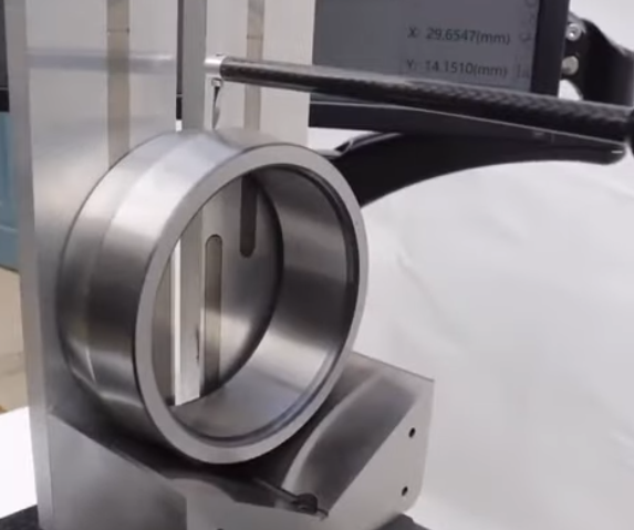
Measuring Internal Features
Internal diameters and depths are often more difficult to measure due to limited access. Options include:
- Inside micrometers and bore gages for holes and cylindrical bores
- Depth micrometers or depth gages for pockets and grooves
- CMM probing for internal features with constrained access
For bore gages, setting rings or master rings are used to set and verify zero before measuring multiple parts.
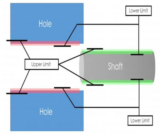
Measuring Diameters and Cylindricity
For cylindrical parts, diameter, roundness, and cylindricity are important:
- Two‑point measurement (e.g., micrometer) gives local size but may not reveal out‑of‑round conditions
- Multiple diameters around the circumference at different axial positions help detect ovality and taper
- Roundness testers or CMM scanning provide detailed form evaluation for tight form tolerances
For critical shafts or bores, measurement strategy must address both size and form if the specification includes cylindricity or roundness requirements.
Checking Angles, Chamfers, and Radii
Angular and contour features are common on CNC parts:
- Angles: measured with sine bars, angle gages, digital protractors, or CMM
- Chamfers: measured by combination of length and depth, or dedicated chamfer gages
- Radii: measured with radius gages for simple verification or by optical and CMM methods for accurate assessment
When angles and radii are critical to function, coordinate methods (CMM, vision systems, optical comparators) are favored over purely mechanical fits.
Measuring Geometric Tolerances on CNC Parts
Geometric tolerances control shape, orientation, and position beyond simple size limits. Accurate verification requires careful datum setup and measurement strategies.
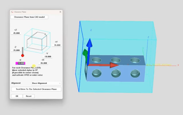
Datums and Coordinate Systems
Geometric tolerances are defined relative to datums. For consistent measurement:
- Establish a part coordinate system following the drawing’s datum scheme
- Physically simulate datums using flat surfaces, pins, or fixtures for manual measurement
- Digitally simulate datums with best‑fit or constrained alignment on CMMs
Incorrect datum setup is a frequent source of apparent nonconformity, even when the part meets design intent.
Form Tolerances: Flatness, Straightness, Roundness
Form tolerances define shape independant of datums:
- Flatness: measured by CMM, surface plate with dial indicator, or flatness gages
- Straightness: assessed along a line using indicators or coordinate measurements
- Roundness: measured using roundness testers or CMM for cylindrical surfaces
Form errors can be much smaller than size tolerances and may require measurement resolution at micrometer level or better.
Orientation Tolerances: Perpendicularity, Parallelism, Angularity
Orientation tolerances control feature angle relative to datums. Common methods:
- Perpendicularity: checking surfaces or axes against a reference square or pedestal, or using CMM relationships
- Parallelism: evaluating height differences over the length of a part or using multiple contact points on a surface plate
- Angularity: verifying specified angles using sine bars, angle blocks, or coordinate methods
For high‑precision orientation tolerances, digital measurement and data analysis are preferred to minimize operator dependency.
Location Tolerances: Position, Concentricity, Symmetry
Location tolerances ensure correct feature placement:
- Position: commonly used for holes and pins; measured by CMM, optical systems, or precise layout methods
- Concentricity: requires evaluation of median points; frequently replaced by runout due to complexity
- Symmetry: evaluated by measuring deviations of features from center planes or axes
Position tolerances are usually expressed with reference to a datum system and often use cylindrical tolerance zones for holes and pins.
Runout and Profile Tolerances
Runout and profile control complex relationships between form, orientation, and location.
- Circular and total runout are generally evaluated by rotating the part about a datum axis and recording indicator variation
- Profile tolerances require comparing measured points or surfaces to the nominal profile from CAD data
CMMs and advanced measuring systems are commonly employed for profile and runout verification, especially for complex or freeform surfaces.
Surface Finish Measurement on CNC Parts
Surface finish affects friction, wear, sealing, fatigue, and appearance. Correct measurement and interpretation are essential when finish is specified.
Surface Texture Parameters
Common parameters include:
- Ra: arithmetic mean roughness, widely used for general finish control
- Rz: average maximum peak‑to‑valley height over several sampling lengths
- Rq: root mean square roughness, more sensitive to high peaks and valleys
- Rt: total height of the roughness profile within the assessment length
Interpretation must follow the specified standard (ISO, ASME) because definitions and default settings may differ.
Measurement Technique and Direction
Surface roughness is direction‑dependent:
- Probing direction is typically perpendicular to the lay (dominant surface pattern)
- Cut‑off length and evaluation length should match the expected roughness scale and specified standard
- The stylus should be correctly placed to avoid edges, steps, or contamination
For very small features, micro‑roughness, or sensitive surfaces, non‑contact optical methods may be required.
In‑Process Versus Final Inspection of CNC Parts
Accurate measurement must be integrated into both in‑process control and final inspection to ensure consistent part quality.
In‑Process Measurement at the Machine
In‑process checks are performed to correct machining offsets before parts go out of tolerance. Typical approaches:
- On‑machine probing for tool offset adjustments and feature verification
- Hand gages and go/no‑go gages used by machinists at the machine
- Quick measurement cycles focusing on a subset of critical dimensions
These checks emphasize speed and repeatability while maintaining adequate accuracy for process control decisions.
Final Inspection and Sampling
Final inspection verifies conformance prior to shipment or assembly. Key practices:
- Use of higher‑accuracy instruments and controlled environment
- Application of sampling plans for batch production (e.g., acceptance based on lot size and criticality)
- Measurement of full GD&T requirements for representative samples if part complexity is high
Final inspection results are typically documented formally and may be required by customers or regulatory bodies.
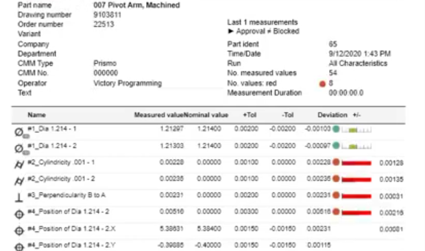
Measurement Data Recording and Reporting
Systematic recording and reporting convert raw measurements into actionable information for quality control and process improvement.
Inspection Plans and Check Sheets
An inspection plan links drawing requirements to specific measurement actions. It typically includes:
- Feature description and drawing reference
- Nominal, upper and lower tolerance limits
- Measurement instruments to be used
- Measurement frequency and sampling method
Check sheets or electronic forms standardize data entry and reduce omissions and transcription errors.
Measurement Records and Statistical Analysis
Recorded data supports both compliance demonstration and process evaluation. Common approaches include:
- Recording actual measured values, not just pass/fail status
- Using control charts to monitor key characteristics over time
- Evaluating process capability indices (Cp, Cpk) for critical dimensions
Sustained analysis of measurement data helps identify drift, tool wear, and opportunities for machining process optimization.
Common Issues and Practical Considerations
Even with good instruments and procedures, several recurring issues can compromise measurement results and lead to disputes or rework.
Misinterpretation of Drawings and Tolerances
Ambiguous or misunderstood specifications often cause inconsistent acceptance decisions. To mitigate this:
- Confirm GD&T interpretations with design engineers when unclear
- Maintain internal guidelines and examples for complex callouts
- Ensure consistent datum references between manufacturing and inspection
Clear communication between design, manufacturing, and quality ensures that measurement matches design intent.
Operator Technique and Training
Manual measurement is heavily influenced by technique. Inconsistent contact force, misalignment, and inadequate part support can add significant variability. Training should cover:
- Correct handling of micrometers, calipers, and indicators
- Proper use of fixtures, V‑blocks, and parallels
- Awareness of temperature and cleanliness effects
Standardized work instructions with illustrations and measurement examples support consistent practice across operators.
Instrument Suitability Limits
Using instruments at the edge of their capability causes unreliable results. Consider:
- Matching instrument accuracy and resolution to tolerance width
- Using CMM or high‑precision tools instead of calipers for tight tolerances
- Replacing worn gages and contact points promptly
Periodic gage studies, such as Gage R&R, can quantify measurement system variability and guide improvements.
Summary: Building a Robust CNC Measurement System
Accurate measurement of CNC machined parts results from a combination of clear requirements, appropriate instruments, controlled environment, defined procedures, and trained personnel. A robust system includes:
- Thorough interpretation of drawings, GD&T, and surface specifications
- Instrument selection based on required accuracy, geometry, and accessibility
- Environmental and preparation controls for parts and tools
- Standardized strategies for dimensional, geometric, and surface measurements
- Consistent recording, reporting, and analysis of measurement data
Implementing these elements provides reliable verification of CNC parts, reduces scrap and rework, and supports stable, predictable machining processes.
FAQ: Measuring CNC Parts Accurately
What tools are commonly used to measure CNC parts accurately?
Common tools include calipers, micrometers, height gauges, dial indicators, and Coordinate Measuring Machines (CMMs) rather than calipers, especially when tolerances are ±0.01 mm or tighter. Surface plates with height gages are suitable for flatness and height checks, while surface roughness testers are needed when finish is critical. Instrument selection should always match or exceed the accuracy and resolution demanded by the tolerances.
What is the difference between a caliper and a micrometer?
Calipers are versatile and suitable for general measurements, while micrometers provide higher accuracy and are used for tight tolerances and critical dimensions.
How does temperature affect CNC part measurements?
Temperature changes cause materials to expand or contract, altering measured dimensions. Since dimensional references are typically at 20 °C, parts, instruments, and reference standards should be near this temperature during inspection. Measuring parts directly after machining, or with significant temperature differences, can introduce errors of several micrometers or more, enough to misjudge tolerance conformance for precision components.
When should a Coordinate Measuring Machine (CMM) be used?
CMMs are ideal for complex geometries, tight tolerances, and high-volume inspection where repeatability and accuracy are critical.
What are common measurement mistakes in CNC machining?
Common mistakes include improper tool calibration, inconsistent measurement pressure, ignoring temperature effects, and measuring parts before they have fully cooled.
