
CNC machining can hold tight dimensions, but achieving stable, high-quality surface finish is often more difficult. Surface finish problems usually result from a combination of cutting parameters, tooling, machine condition, workholding, and material behavior. Understanding these factors and their interactions is essential for diagnosing defects and defining reliable corrective actions.
What Surface Finish Means in CNC Machining
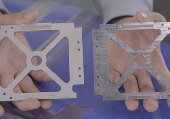
In CNC machining, surface finish describes the texture of a machined surface at a microscopic scale. It reflects peaks and valleys left by the cutting tool and is usually quantified by standard roughness parameters measured over a defined sampling length.
Main Surface Roughness Parameters
The most widely used parameters are based on ISO 4287 / ISO 4288 and related standards:
- Ra (Arithmetic Average Roughness): Average absolute deviation of the surface profile from the mean line. Common in general engineering specifications.
- Rz (Average Maximum Height): Average of the vertical distance between the highest peak and lowest valley within several sampling lengths.
- Rq (Root Mean Square Roughness): RMS value of profile deviations; more sensitive to large peaks and valleys than Ra.
- Rt (Total Height): Vertical distance between the highest peak and lowest valley within the evaluation length.
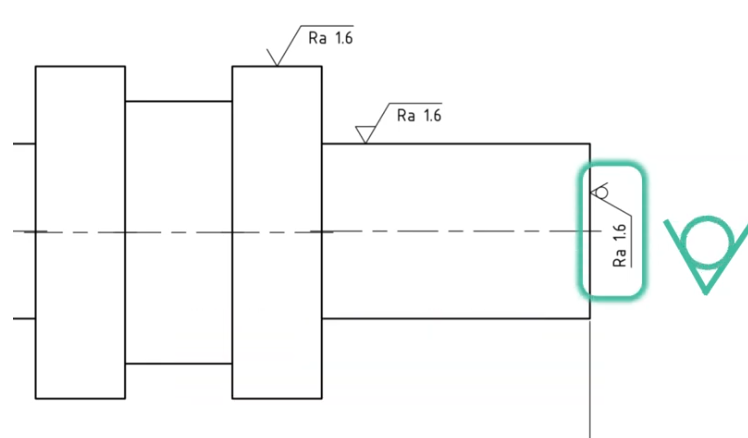
Ra is typically used for technical drawings unless a special functional requirement specifies another parameter.
Typical Surface Finish Ranges by Process
| Process | Typical Ra (µm) – Standard Cutting | Typical Ra (µm) – Fine / Finishing |
|---|---|---|
| CNC turning | 1.6 – 6.3 | 0.4 – 1.6 |
| CNC milling (face/end) | 1.6 – 6.3 | 0.4 – 1.6 |
| Drilling (standard twist drill) | 3.2 – 12.5 | — |
| Reaming | 0.8 – 3.2 | 0.4 – 0.8 |
| Grinding | 0.1 – 0.8 | 0.05 – 0.2 |
| Honing / lapping | 0.01 – 0.2 | 0.01 – 0.05 |
How to Measure CNC Surface Finish
Accurate assessment of surface finish is essential for troubleshooting and process control. Choice of method depends on required precision, surface accessibility, and production environment.
Contact Profilometers
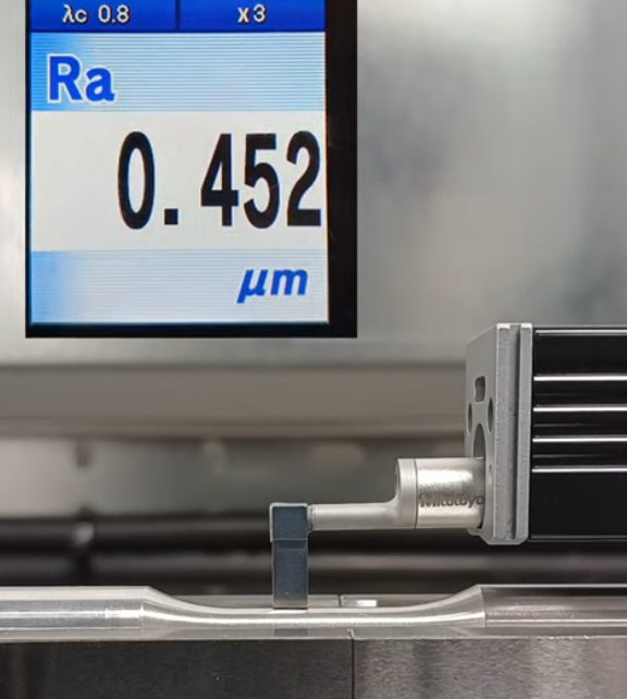
Contact profilometers use a stylus with a defined tip radius (commonly 2 µm or 5 µm) that traverses the surface at a controlled speed, typically 0.1–1 mm/s. Vertical resolution is often in the nanometer range, with measurement length and cut-off values selected according to the expected roughness.
Key settings include:
- Sampling length (λc), for example 0.8 mm or 2.5 mm.
- Number of sampling lengths (usually 5) to form the evaluation length.
- Filter type (Gaussian filter is common).
Non-Contact Measurement
Non-contact options are useful for delicate surfaces or where stylus access is limited:
- Optical interferometers for very fine surfaces below 0.1 µm Ra.
- Confocal microscopy for localized, high-resolution 3D topography.
- Laser scanning systems integrated in machine tools for in-process checking.
Simple Shop-Floor Checks
For quick evaluations, operators may use:
- Surface finish comparators (reference plates with known Ra values).
- Visual inspection under uniform lighting and magnification.
- Fingernail or fingertip feel for gross defects like burrs or deep tool marks.
These methods cannot replace metrology-grade measurement but help to detect obvious deviations before full inspection.
Typical CNC Surface Finish Problems
Surface finish defects can be grouped by their visual appearance and underlying physical cause. Recognizing patterns is the first step toward an effective diagnosis.
Tool Marks and Chatter Marks
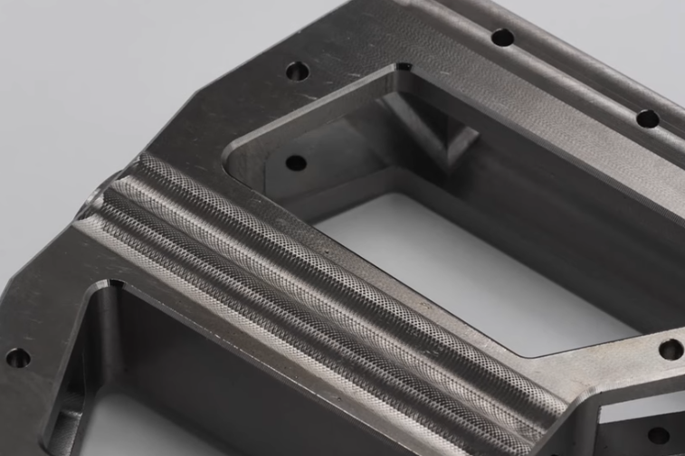
Tool marks appear as regular lines or spirals that follow the cutting path. Chatter marks are wavy patterns with a characteristic wavelength resulting from vibration. They degrade appearance and may reduce fatigue strength.
Tearing, Smearing, and Built-Up Edge
In ductile materials, inadequate cutting conditions can cause tearing and smearing. Built-up edge (BUE) forms when work material adheres to the cutting edge, periodically breaking off and leaving irregular impressions on the surface.
Feed Lines, Step Marks, and Scallops
On milled or turned surfaces, feed lines and step marks arise from excessive feed per revolution or improper step-over. On 3-axis contoured surfaces, scallops appear when the tool path step-over is too large relative to tool radius and required Ra.
Burrs and Edge Defects
Burrs are undesired material protrusions at edges or exit points of cuts and holes. They complicate assembly, can damage mating parts, and often indicate suboptimal cutting parameters, tool wear, or insufficient support during breakthrough.
Surface Burns, Discoloration, and Hard Layers
Overheating during cutting or grinding can cause localized burning, temper colors, microstructural changes, and hard layers. Even when the roughness values appear acceptable, such thermal damage can lead to cracking or premature failure.
Dimensional Accuracy vs. Surface Finish Conflicts
Settings that optimize surface finish sometimes conflict with those needed for tight geometry and productivity. For example, very low feed and depth of cut may improve Ra but increase deflection and thermal effects, creating taper or out-of-roundness. Balancing these constraints is a recurring issue in process planning.
Main Causes of Poor Surface Finish in CNC Machining
Surface finish is influenced by a wide set of interacting factors. Identifying the dominant root cause is essential for efficient correction.
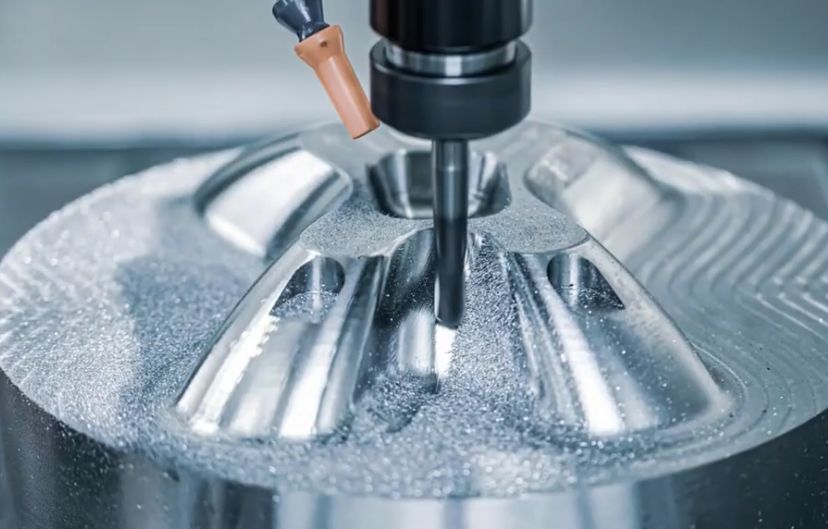
Cutting Parameters and Toolpath Strategy
Cutting parameters have a direct and quantifiable effect on surface finish. In many cases, inappropriate combinations of feed, speed, and depth of cut are the primary cause of defects.
Feed Rate and Surface Roughness
For turning, a simplified theoretical roughness for an ideal tool nose radius (rε) and feed per revolution (f) is often approximated by:
Ra ≈ f² / (32 × rε)
This indicates that:
- Higher feed rates significantly increase Ra.
- Larger nose radii tend to reduce theoretical roughness.
In milling, feed per tooth (fz) and tool path direction (climb vs conventional) influence both roughness and force. Excessive feed produces pronounced feed marks and can exacerbate vibration, especially on flexible setups.
Spindle Speed and Cutting Speed
Cutting speed (vc) affects chip formation, tool wear mechanism, and thermal conditions at the cutting zone. Too low vc can promote built-up edge formation; too high vc may accelerate flank wear, crater wear, and thermal cracking. Both extremes often worsen surface finish.
Depth of Cut and Step-Over
Depth of cut (ap, radial or axial depending on operation) must suit the tool geometry and machine rigidity. Very small depths can cause rubbing instead of cutting, generating heat and poor finish. Very large depths increase cutting forces and can induce chatter.
In milling, step-over (ae) directly affects cusp height on 3D surfaces. To achieve a given Ra, step-over must be matched with tool radius, especially for ball end mills or bull nose cutters.
Toolpath Patterns and Entry/Exit Strategies
Toolpath choice affects load distribution, direction of cutting forces, and overlap between passes:
- Climb milling usually gives better surface finish than conventional milling on rigid machines.
- Constant step-over toolpaths provide more uniform scallop height than simple raster paths.
- Optimized entry and exit moves reduce dwell marks and defects at retraction points.
Tooling-Related Causes of Surface Finish Problems
Tool condition is a critical contributor to surface finish. The best cutting parameters cannot compensate for inappropriate or degraded tooling.
Tool Wear and Edge Degradation
Wear changes the effective geometry of the tool and increases friction at the tool–workpiece interface. Typical wear behaviors include:
- Flank wear: Progressive wear on the clearance surface; high flank wear increases contact area and roughness.
- Crater wear: Occurs on the rake face; may promote built-up edge and change chip flow.
- Notching: Localized wear at the depth-of-cut line; often leads to steps or ridges on the machined surface.
- Micro-chipping: Small breakouts along the cutting edge; leaves repetitive marks and micro-defects on the surface.
Beyond a certain wear land width, typically around 0.2–0.3 mm for many carbide tools, surface finish deteriorates rapidly.
Tool Geometry and Nose Radius
Tool geometry must be selected for both material and finish requirements:
- Rake angle: Too small may increase cutting force and deformation; too large can weaken the edge.
- Relief angle: Insufficient relief causes rubbing; excessive relief can reduce edge strength.
- Nose radius: Larger radii generally provide smoother surfaces but increase radial forces.
For finishing operations, dedicated inserts or cutters with polished rake surfaces and optimized chip breakers often yield better surface finish than general-purpose tools.
Tool Material and Coating
The combination of substrate and coating affects friction, adhesion, and heat management:
- Uncoated carbide for non-ferrous materials can help avoid built-up edge and smearing.
- Coated carbide (such as TiN, TiCN, AlTiN) for steels improves wear resistance and can stabilize surface finish over longer tool life.
- PCD and CBN tools are suitable for hard or abrasive materials and can achieve very low roughness if cutting conditions are controlled.
Incorrect coating choice may increase adhesion or thermal load, leading to inconsistent finish.
Tool Runout and Holder Quality
Tool runout causes uneven load distribution among cutting edges and leaves periodic marks on the surface. Sources include:
- Worn or contaminated collets and chucks.
- Improper tool seating or chip contamination in the taper.
- Unbalanced tool assemblies at high spindle speeds.
Hydraulic chucks, shrink-fit holders, and quality collets with regular maintenance can significantly reduce runout and improve surface consistency.
Machine and Workholding Effects on Surface Finish
The machine tool and workholding system define the stiffness, dynamic behavior, and positioning accuracy of the cutting process. Insufficient rigidity is a frequent but often overlooked cause of poor surface finish.
Machine Rigidity and Structural Dynamics
Machine stiffness against cutting forces determines how much the tool and workpiece deflect during machining. Low stiffness or poor damping results in vibration and chatter. Common contributors include:
- Over-extended quills and boring bars.
- Long tool overhangs relative to shank diameter.
- Light-duty machine structures or worn linear guideways.
- Loose gibs or insufficient preload on bearings.
In such cases, even moderate cutting forces can cause dynamic instabilities, producing characteristic chatter marks on the surface.
Backlash, Servo Tuning, and Interpolation Errors
Positioning inaccuracies and non-smooth axis motion generate small deviations and marks, especially on circular and free-form paths. Causes include:
- Backlash in ballscrews due to wear or improper preloading.
- Servo tuning issues leading to overshoot, lag, or oscillations.
- Interpolation errors at high feed, especially on older controls or with limited look-ahead.
These issues can lead to faceting on supposedly smooth contours and variable surface finish along the path.
Thermal Effects and Coolant Management
Heat generation during cutting can cause thermal expansion of both the part and the machine structure. If not controlled, it leads to variable chip thickness and surface quality changes over time. Coolant conditions that matter include:
- Coolant type: Emulsion, straight oil, or minimum quantity lubrication (MQL).
- Flow rate and direction: Proper targeting of the cutting zone, especially in deep pockets or bores.
- Coolant temperature stability: Large temperature variations can cause drift in machine geometry.
Insufficient coolant flow may result in localized overheating and surface burns; excessive or poorly directed coolant can cause thermal shock or chip recutting.
Workholding, Clamping, and Vibration
Workholding defines boundary conditions for part stiffness and vibration behavior. Inadequate support or excessive clamping force can both damage surface finish:
- Flexible parts may vibrate and resonate with cutting forces.
- Thin walls can deflect under side loads, leading to chatter and non-uniform surface texture.
- Excessive clamping can imprint jaw marks or distort the part; insufficient clamping leads to micro-movements.
Support fixtures, soft jaws, and carefully planned clamping sequences are necessary for consistent surface quality on thin or complex parts.
Material-Related Factors Affecting Surface Finish
Each material has specific machinability characteristics that influence the achievable surface finish under given conditions.
Mechanical Properties and Microstructure
Material hardness, ductility, and microstructure determine chip formation and tendency to form built-up edge:
- Very soft, ductile metals (like pure aluminum or copper) tend to smear and produce built-up edge at low cutting speeds or with dull tools.
- Work-hardening alloys require careful control of cutting parameters and sharp tools to avoid surface hardening and tearing.
- Casting pores, inclusions, or segregations can cause local surface pits and roughness variations.
Inclusions, Coatings, and Surface Condition of Stock
Pre-existing conditions on the raw material, such as scale, corrosion, or coatings, can interfere with chip formation, causing tool wear and roughness spikes. Removing the outer layer with a dedicated roughing pass before finishing helps to stabilize the results.
Machinability and Cutting Data Selection
Material-specific cutting data from tool manufacturers provide starting values for speed, feed, and depth of cut. Ignoring these references often leads to inappropriate parameter choices. Adjustments are usually needed to align with the rigidity of the actual setup and desired surface finish level.
Process Planning and Programming Considerations
Beyond individual parameters, overall process planning and CNC programming strategy strongly affect surface finish outcomes.
Roughing vs. Finishing Strategies
Separating roughing and finishing passes is a fundamental method for controlling surface finish:
- Roughing removes bulk material with high material removal rate and moderate finish.
- Finishing leaves a small, uniform allowance (for example 0.1–0.3 mm) for a dedicated pass with optimized parameters.
Using dedicated finishing tools and passes minimizes the impact of roughing-induced stresses, deflections, and tool wear on the final surface.
Cutter Engagement and Load Control
Consistent cutter engagement helps to maintain stable cutting forces and surface finish. Sudden changes in engagement can cause tool deflection and visible traces on the part. Toolpaths that maintain constant engagement (for example, trochoidal or adaptive milling in roughing, and uniform step-over in finishing) contribute to more uniform surface appearance.
Step-Over and Scallop Height in 3D Machining
On free-form surfaces, step-over must be set to achieve the required scallop height. For ball end mills, theoretical cusp height is a function of tool radius and transverse step-over. Reducing step-over decreases cusp height but increases machining time. Choosing an appropriate compromise is essential when tolerance and functional requirements allow some residual texture.
Use of Lead-in, Lead-out, and Over-travel
Transition zones, where the tool engages and disengages the material, are prone to marks and dwell lines. Adding lead-in and lead-out arcs, ramping strategies, or over-travel beyond the functional surface reduces these localized defects.
Common Issue in CNC Surface Finish Control
Shops frequently encounter recurring issues when trying to meet surface finish requirements:
Balancing Cycle Time and Surface Quality
Higher feed rates and deeper cuts reduce cycle time but usually degrade surface finish. Trying to meet tight Ra limits with purely roughing-style parameters often fails and leads to repeated rework or manual polishing.
Maintaining Consistency over Long Production Runs
Surface finish may deteriorate gradually as tools wear, coolant conditions change, or machine temperature stabilizes at a different level. Without monitoring and timely adjustment, the first parts meet specifications while later batches drift out of tolerance.
Thin-Wall and Complex Geometry Parts
Thin walls and slender features easily vibrate and deflect under cutting forces. Even with correct feed and speed, the lack of rigidity leads to chatter, ribbing, or localized rough spots, especially near unsupported regions or corners.
Meeting Tight Finish on Hard or Abrasive Materials
Hard steels, superalloys, and abrasive composites accelerate tool wear and demand precise control of cutting conditions. Achieving demanding Ra values on such materials often requires optimized tooling, rigid setups, and carefully tuned finishing passes.
Diagnosing CNC Surface Finish Problems Systematically
Effective troubleshooting requires structured observation and elimination of potential causes.
Visual and Tactile Inspection
Begin with a systematic inspection of the affected surfaces:
- Identify pattern direction (parallel to feed, perpendicular to feed, circular, random).
- Check for localized vs. global defects across the part.
- Feel for steps, ridges, high spots, or burrs with fingers or a clean cloth.
Correlation with Toolpath and Operation Data
Match defect locations and patterns with the toolpath, program segments, and tool changes:
- Determine whether defects appear after a specific tool, pass, or change in feed/speed.
- Check NC program for abrupt parameter changes or feed/speed overrides applied by the operator.
- Identify whether defects correspond to direction changes, corners, or re-entry points.
Inspection of Tools, Holders, and Workholding
Examine the cutting tools and workholding elements for visible issues:
- Inspect cutting edges under magnification for wear, chipping, or built-up edge.
- Check tool runout and verify correct seating and tightening of holders.
- Assess clamping points, supports, and fixture rigidity, especially for thin or long parts.
Measurement and Trend Analysis
Use surface roughness data to identify trends:
- Measure Ra and other relevant parameters at multiple locations on the part.
- Compare results from early and late parts within the same production lot.
- Correlate measured roughness with tool life, coolant condition, or machine warm-up time.
Machine Condition and Dynamics Checks
If tooling and parameters appear correct, investigate machine condition:
- Check spindle bearings for excessive play or unusual noise.
- Evaluate axis backlash and follow-up errors using diagnostic functions if available.
- Monitor vibration using accelerometers or machine integrated sensors where possible.
Practical Ways to Improve CNC Surface Finish
Once the main cause is identified, targeted corrective actions can significantly improve surface finish.
Parameter Adjustment for Finishing
For dedicated finishing passes:
- Reduce feed per tooth or feed per revolution to achieve desired Ra, within the stability limits of the setup.
- Use moderate cutting speeds recommended for finishing in the given material with the selected tool.
- Set a small and consistent depth of cut; avoid combining roughing and finishing in one pass where high quality is required.
Tool Optimization and Maintenance
Improve tooling choices and care:
- Use high-quality finishing inserts, polished cutting edges, and appropriate nose radii.
- Replace tools before they reach severe wear, based on defined tool life or wear limits.
- Use holders with low runout and maintain them regularly (cleaning tapers, checking clamping forces).
Enhancing Rigidity and Workholding
Increase stiffness where possible:
- Reduce tool overhang and choose larger tool diameters when compatible with geometry.
- Support thin walls with auxiliary fixtures or temporary ribs where design allows.
- Use additional clamps, tailstocks, or steady rests for long workpieces.
Coolant and Chip Control
Optimize coolant delivery and chip evacuation:
- Ensure sufficient coolant flow to the cutting zone, especially in deep pockets and holes.
- Use through-coolant tools when appropriate to reduce heat and remove chips.
- Prevent chip recutting by configuring toolpaths and coolant streams to clear chips away from the surface.
Program Refinement and Path Smoothing
Refine CNC programs to reduce sudden load changes:
- Use smoothing or high-speed machining options in the CNC control if available.
- Apply lead-in and lead-out motions for finishing passes; avoid abrupt changes in direction.
- Adjust step-over and step-down to balance machining time and surface finish.
Surface Finish and Functional Requirements
Surface finish is not just an aesthetic parameter; it often has direct functional implications and must be aligned with the intended use of the part.
Tribological Performance and Wear
Surface roughness affects friction, lubrication, and wear behavior:
- Too rough surfaces can cause high friction, noise, and rapid wear in sliding applications.
- Overly smooth surfaces may impede lubricant retention if a certain texture is required.
Fatigue Strength and Stress Concentrations
Surface irregularities and machining marks act as stress concentrators. In cyclic loading conditions, poor surface finish can significantly reduce fatigue strength. Controlling surface finish is therefore important in crankshafts, shafts, connecting rods, and structural components subjected to dynamic loads.
Sealing, Assembly, and Aesthetics
Sealing surfaces often require controlled surface finish to achieve leak-tight joints without excessive gasket wear. Assembly surfaces may need a certain finish to ensure press-fits or sliding fits behave as intended. Visible surfaces may have aesthetic requirements beyond purely functional considerations.
Linking Drawings, Specifications, and Process Capability
Engineering drawings often specify surface roughness values that must be realistic and compatible with the chosen production route. When required Ra values are significantly lower than the process capability of the planned machining operations, secondary processes such as grinding, honing, or polishing may be necessary.
Quick Reference: CNC Surface Finish Issues and Causes
| Observed Issue | Likely Causes | Typical Corrective Actions |
|---|---|---|
| Regular feed marks, rough texture | Feed too high, nose radius too small, tool wear | Reduce feed, increase nose radius, replace or regrind tool |
| Chatter marks, waviness | Insufficient rigidity, excessive depth of cut, tool overhang, poor workholding | Increase stiffness, shorten tool, reduce depth of cut, adjust clamping |
| Tearing and smearing | Dull tool, low cutting speed, built-up edge, improper coolant | Use sharp tools, optimize speed, improve coolant, choose suitable tool geometry |
| Random pits or spots | Inclusions or porosity in material, chip recutting, contamination | Change material batch if needed, improve chip evacuation, clean setup |
| Burn marks, discoloration | Overheating due to low coolant, excessive speed or feed, rubbing | Improve cooling, adjust speed and feed, avoid rubbing passes |
| Burrs and sharp edges | Improper breakthrough conditions, dull tools, lack of deburring strategy | Optimize exit conditions, use sharp tools, include deburring operations |
| Faceted surfaces in contours | Low interpolation resolution, high feed, control smoothing off | Enable smoothing, reduce feed, increase control look-ahead |
FAQ: CNC Surface Finish Problems
What does “surface finish” mean in CNC machining?
Surface finish refers to the texture, smoothness, or roughness of a machined surface after processing. It is typically measured as surface roughness (Ra, Rz, etc.) and indicates how smooth or polished the final part is.
What units are used to describe surface finish?
Common units include:
Ra (Roughness Average) – the most widely used
Rz (Mean Roughness Depth)
RMS (Root Mean Square)
Values are usually expressed in micrometers (µm) or microinches (µin).
What surface finishes are common in CNC machining?
Typical surface roughness levels:
Ra 3.2–6.3 µm – standard machining
Ra 1.6 µm – fine finishing
Ra 0.8 µm or below – high-precision finishing
Ra 0.2 µm or below – superfinishing / polishing
How can I improve surface finish in CNC machining?
You can improve finish by:
Increasing spindle speed
Reducing feed rates for finishing passes
Using sharper or specialized tools
Reducing tool stick-out
Using climb milling
Ensuring stable workholding
Applying proper coolant
Does material type affect surface finish?
Absolutely. For example:
Aluminum → easy to achieve smooth finish
Stainless steel & titanium → more difficult due to toughness
Plastics → may melt or burr if not cut correctly
Brass → naturally produces excellent surface finish
