
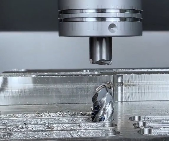
Cutting tool chipping is one of the most frequent and costly issues in CNC machining. It leads to sudden tool failure, short tool life, dimensional inaccuracies, poor surface finish, and unplanned downtime. Understanding the mechanisms behind chipping and how to prevent it is essential for stable, economical production.
What Is Cutting Tool Chipping?
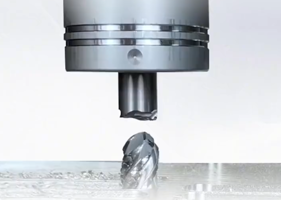
Cutting tool chipping is a localized, small-scale fracture or breaking away of material from the cutting edge or flank of a tool. Unlike gradual flank wear or crater wear, chipping is usually abrupt and can propagate quickly into larger fractures or total tool breakage.
Chipping can occur on:
- Cutting edge corner (corner chipping)
- Main cutting edge line (edge chipping)
- Coating layer only (coating spalling or micro-chipping)
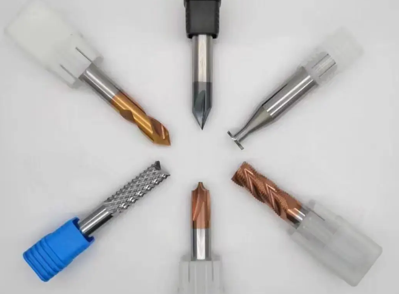
Chipping is common on:
- Indexable carbide inserts
- Solid carbide mills and drills
- Ceramic, cermet, and PCBN inserts
Because chipping often occurs unexpectedly, it can cause immediate deterioration in surface finish, size deviation, and the risk of tool fragments damaging the workpiece or fixture.
Fundamental Mechanisms of Tool Chipping
Tool chipping is driven by a combination of mechanical, thermal, and tribological mechanisms acting on the tool-workpiece-chip interface.
Mechanical Overload and Impact
Mechanical overload occurs when the cutting edge is subjected to forces exceeding its fracture toughness. This can happen due to excessive feed per tooth, large depth of cut, interrupted cuts, or collisions.
Impact loading is particularly severe in:
- Milling of castings with hard spots or sand inclusions
- Interrupted turning (keyways, shoulders, holes, slots)
- Drilling across cross-holes or inclined surfaces
Thermal Stress and Thermal Shock
Cutting generates high temperatures in a small contact zone. Rapid temperature fluctuations cause differential expansion and contraction within the tool, producing thermal stresses. When these stresses exceed the tool’s strength, micro-cracks initiate and grow, leading to chipping.
Thermal shock is intensified by:
- Intermittent coolant application (on–off cycles)
- High cutting speed with poor heat dissipation
- Machining heat-resistant alloys at aggressive parameters
Abrasive, Adhesive, and Fatigue Effects
Abrasive wear caused by hard particles, carbides in steel, or work-hardened surfaces can generate micro-notches along the cutting edge, which act as crack initiation sites. Adhesive wear, where workpiece material welds to the tool and then tears away, can remove coating and weaken the edge.
Under cyclic loading (especially in milling and interrupted cuts), fatigue cracks can form at these defects and extend gradually until sudden chipping occurs.
Main Causes of Cutting Tool Chipping in CNC Machining
While the physical mechanisms are similar, practical causes in a CNC environment can be grouped into tool-related, cutting parameter-related, workpiece-related, and machine/fixturing factors.
Tool Material and Grade Selection
Each tool material has a characteristic combination of hardness, toughness, and heat resistance. Misalignment between tool material and application is a primary cause of chipping.
| Tool Material | Typical Application | Chipping Risk Characteristic |
|---|---|---|
| Uncoated Carbide | General turning, milling of steels and cast iron | Moderate toughness, higher chipping risk in high-speed or dry cutting |
| Coated Carbide (TiN, TiCN, TiAlN, etc.) | Versatile; wide range of steels, cast iron, stainless, superalloys | Improved wear resistance; chipping occurs if coating delaminates or edge is too sharp |
| Cermet | Finishing steel and cast iron at high speed | High wear resistance but relatively brittle; sensitive to impact and interrupted cuts |
| Ceramic (Al2O3, SiAlON) | High-speed machining of cast iron, heat-resistant alloys | Very brittle; high chipping risk under interrupted cuts or thermal shock |
| PCBN | Hard turning of hardened steels, chilled cast iron | High hardness, limited toughness; chipping at high mechanical shock or misalignment |
| PCD | Aluminum, non-ferrous alloys, composites | Extreme hardness; notch and edge chipping when cutting ferrous materials or interrupted cuts |
Common selection-related causes:
Using a grade that is too hard and brittle for unstable setups, roughing operations, or heavy interrupted cuts, leading to corner chipping and edge fracture.
Using a grade that is too tough and soft, which increases flank wear and notch wear; once a notch forms, chipping propagates from this weakened area.
Geometry, Edge Preparation, and Chipbreaker Design
Tool geometry has a strong influence on stress distribution and chip flow. Key aspects include rake angle, clearance angle, edge radius, land width, and chipbreaker shape.
Typical geometry-related causes of chipping:
Excessively sharp edges (small edge radius) concentrate stress and make the edge sensitive to micro-defects. Positive rake and thin edge cross-sections reduce cutting forces but also reduce mechanical strength, especially in interrupted cuts.
Insufficient edge honing or improper edge preparation leads to micro-notches originating from grinding marks. These can evolve into cracks under load.
Chipbreaker design that does not match feed and depth of cut can cause poor chip curling and chip packing. Built-up edge (BUE) formation or chip hammering against the tool face can induce local chipping at the cutting edge.
Cutting Parameters: Speed, Feed, and Depth of Cut
Incorrect cutting data are among the most frequent causes of chipping. Each tool grade and geometry has a recommended range of cutting speed (vc), feed per tooth or per revolution (fz, fn), and depth of cut (ap, ae).
| Parameter | Typical Range (Example, Steel) | Influence on Chipping When Misapplied |
|---|---|---|
| Cutting Speed vc | 150–260 m/min for coated carbide turning | Too high: elevated temperature, thermal cracking and chipping; too low: BUE and edge breakage |
| Feed per rev fn (turning) | 0.10–0.35 mm/rev roughing, 0.05–0.15 mm/rev finishing | Too high: mechanical overload, corner chipping; too low: rubbing, BUE, vibration-induced chipping |
| Radial DOC ae (milling) | 0.05–0.4 × cutter D depending on operation | Too high: high chip load and impact; too low: intermittent engagement, chatter, edge chipping |
| Axial DOC ap | 0.5–4.0 mm for general milling; up to 6–8 mm for heavy roughing | Extreme ap with low rigidity causes vibration, leading to chipping along the edge |
Common parameter-related problems include:
Running high speed and feed simultaneously during roughing with a brittle grade; using high speed in heat-resistant alloys without adequate coolant or optimized geometry, causing thermal cracking; applying finishing feeds with roughing inserts causing intermittent contact and micro-chipping.
Coolant, Lubrication, and Chip Evacuation
Coolant and lubrication influence temperature, friction, built-up edge, and chip evacuation. Poor control in any of these areas can contribute to chipping.
Key coolant-related causes:
Intermittent coolant application in high-speed or high-temperature applications leads to thermal shock, especially for ceramics, cermets, and some carbide grades. Insufficient coolant flow in drilling and deep milling leads to chip packing and recutting of chips, which can break the cutting edge.
Low coolant concentration or improper coolant type reduces lubricity and increases friction and adhesion, leading to localized heating and micro-cracks. In some cases (e.g., cast iron milling with carbide), unnecessary flood coolant promotes thermal cycling and chipping, where dry cutting would be more stable.
Workpiece Material and Hardness Variations
Workpiece material behavior under cutting is critical. Certain materials have characteristics that inherently increase the risk of chipping.
Examples:
Hardened steels (HRC 45–65) turn abrasively and can cause micro-notches at the depth of cut line. Any notch becomes a starting point for chipping. Stainless steels and nickel-based alloys tend to work harden if the edge is dull or the feed is too light; the hardened layer accelerates chipping.
Gray and chilled cast iron can contain hard carbides or chilled zones, which act as hard inclusions and create impact loading on the edge. Forgings and castings may have scale, decarburized layers, or localized hardness variations that cause fluctuating cutting forces and occasional edge chipping.
Machine Tool Rigidity, Runout, and Fixturing
Machine and fixturing conditions determine stability. Lack of rigidity or precision leads to vibrations, runout, and dynamic load peaks on the cutting edge.
Key issues include:
Spindle runout in milling or drilling. Excessive runout causes one tooth or flute to carry most of the load, dramatically increasing its chipping probability. Loose or poorly clamped workpieces vibrate under cutting forces, causing edge chatter and intermittent engagement.
Long tool overhang or slender boring bars increase deflection and vibration. This imposes fluctuating loads on the cutting edge and promotes chipping, especially on brittle inserts or solid carbide tools.
Typical Symptoms and Diagnostics of Tool Chipping
Timely detection and correct diagnosis of chipping are essential to define effective countermeasures.
Visual and Dimensional Symptoms
Visual indicators on the tool:
Small missing segments at the cutting edge, typically at the corner radius or along the main cutting edge. Micro-chips or flaking of coating along the cutting edge. Crack patterns perpendicular or oblique to the cutting edge, sometimes originating from the depth of cut line or notch.
Effects on the workpiece include sudden deterioration in surface finish (tearing, scratches, chatter marks), dimensional variation (oversize or taper due to effective cutting edge shift), and burr formation in drilling and milling operations.
Process Monitoring and Tool Life Patterns
Chipping often causes irregular tool life, where tools occasionally fail far earlier than expected. Machinists may report tools that sometimes last 15 minutes and sometimes fail after 3 minutes under seemingly identical conditions.
Monitoring spindle load, vibration, and acoustic emission can reveal spikes correlated with chipping events. In automated production, inconsistent tool life histories are a strong sign that chipping, not uniform wear, is the dominant failure mode.
Effective Solutions to Prevent and Control Chipping
Mitigating cutting tool chipping requires a systematic approach. Isolated adjustments often provide limited benefit; combining appropriate tool selection, geometry, parameters, coolant management, and machine setup yields more robust solutions.
Optimize Tool Material and Grade
Matching toughness and hardness to the operation is fundamental.
For unstable, interrupted, or heavy roughing cuts, choose tougher grades with larger grain size, cobalt-rich binders (for carbide), or specially designated “roughing” or “shock-resistant” grades. For stable finishing with predictable loads, a harder, more wear-resistant grade is appropriate, but avoid those known to be extremely brittle if any interruption or vibration is present.
In heat-resistant superalloys, select grades engineered for hot hardness and thermal crack resistance, and maintain recommended cutting speeds to avoid thermal shock. In hard turning, use PCBN grades with sufficient toughness for the hardness range and interruption level; for light interruptions, mixed PCBN with ceramic binder is often preferred over very hard grades.
Improve Tool Geometry and Edge Preparation
Fine-tuning geometry often yields significant reductions in chipping without slowing cycle time substantially.
Moderate edge rounding is critical. A slight hone (for example, 0.02–0.06 mm radius for finishing, 0.04–0.08 mm for general CNC machining, 0.06–0.15 mm for heavy roughing) increases edge strength and reduces micro-chipping. Too large a hone, however, increases cutting forces and can induce vibration.
Adjust rake angle to balance cutting force and edge strength. Highly positive rake reduces cutting forces but weakens the edge; in unstable conditions, a neutral or slightly negative rake may be more stable even at the cost of higher power consumption.
Select chipbreakers aligned to feed and depth of cut. For example, roughing chipbreakers designed for high feed produce robust chips with less hammering on the tool face. Finishing chipbreakers should be used only within their defined feed range; using them at very low feed leads to poor chip control and possible built-up edge.
Set Cutting Parameters Within Safe Windows
Optimizing cutting data is a direct and effective means to reduce chipping. Parameter changes should be based on the specific failure pattern observed.
If chipping occurs primarily at high speed with good surface finish until failure, reduce cutting speed vc by 10–20% while maintaining or slightly reducing feed to limit thermal load. If corner chipping occurs when increasing feed, reduce feed per tooth or per revolution by 10–30% and consider increasing axial or radial depth to maintain material removal rate.
If chipping is associated with chatter marks or vibration, adjust parameters to move away from resonance, for example by lowering radial depth of cut and increasing feed, or by changing the number of teeth engaged. In drilling and boring, avoid very shallow feeds that cause rubbing; maintain a minimum chip thickness to ensure effective cutting and stable edge loading.
Improve Coolant Strategy and Chip Evacuation
Coolant management should support consistent temperature and reliable chip removal.
For carbide and cermet tools in continuous cuts, apply steady, sufficient flow of coolant at appropriate pressure to maintain a relatively stable temperature and improve lubrication. For ceramic tools in high-speed cast iron or superalloy machining, dry cutting is often recommended to avoid thermal shock, unless specifically designed coolant-compatible grades are used.
In deep-hole drilling, use through-tool coolant with pressures adequate for hole depth and diameter (for example, 10–20 bar for shallow holes in steel, up to 50–70 bar or more for deep holes). Poor chip evacuation leads to chip re-cutting, which can abruptly chip drill lips and corners.
Ensure coolant nozzles are correctly positioned toward the cutting zone rather than the tool shank or non-critical areas. Check coolant concentration regularly; low concentration increases friction, while overly rich concentration may cause foaming and poor flow.

Enhance Machine Stability and Fixturing
Reducing vibration and deflection has a direct effect on preventing chipping.
Minimize tool overhang; as a basic guideline, keep overhang under 4–5 times the tool diameter when possible. For boring bars, consider vibration-damped bars when length-to-diameter ratios above 6–7 are required.
Ensure workpieces are rigidly clamped with adequate support close to the cutting zone. Verify that clamping does not deform thin-walled parts, which can cause dynamic movement under cutting forces.
Measure spindle runout and correct if needed. Tools with BT, HSK, or other tapered interfaces must be clean and correctly seated. Any contamination or damage increases runout and creates uneven load distribution on cutting edges.
Match Tool Path Strategy to Edge Robustness
CAM programming and tool paths directly affect cutting engagement. Abrupt entry and exit or frequent directional changes can produce impact loading on the cutting edge.
Where possible, use ramp-in, helical entry, or pre-drilled entry instead of direct plunging or full-width engagement from the workpiece edge. In milling, use strategies that avoid sudden full-width engagement, such as trochoidal or high-efficiency milling paths with controlled radial engagement.
In turning, avoid cutting across abrupt shoulders or keyways at high feed and speed with brittle grades. Use reduced feed when passing interruptions and then restore normal feed when in continuous cut. For threading and grooving, apply sufficient clearance and avoid dwelling in the cut, which can cause notch formation and eventual chipping.
Workpiece Preparation and Material Control
Pre-processing the workpiece surface and controlling material consistency can significantly reduce chipping risk.
Removing hard scale, case-hardened layers, or casting skin by prior grinding, shot blasting, or light roughing with robust tooling can protect finishing tools from severe impacts. Ensuring consistent material hardness and composition across batches reduces unexpected variations in cutting forces.
When CNC machining welds or build-up areas, anticipate harder zones and adapt tool grade and parameters accordingly. Using tougher grades or lower speeds in weld regions helps avoid sudden edge failure.
Tool Maintenance, Handling, and Replacement Strategy
Proper handling and replacement timing are necessary to prevent premature chipping.
Avoid dropping or knocking inserts and tools during handling; even small micro-cracks from mechanical impact can cause early chipping under load. Make sure clamping screws and pockets are clean and free from chips; contamination can misalign the insert, raising uneven loads on the edge.
Implement tool life management based on measured wear, not just breakage. Replace tools when flank wear or notch wear reaches defined limits (for example, VB <= 0.2–0.3 mm for finishing carbide turning) to prevent transition from wear to chipping.
For multi-flute tools, rotate tools before one flute is heavily worn compared to others; uneven wear increases load on the remaining edges and causes local chipping.
Case-Based Considerations by Operation Type
Different CNC operations present specific patterns of chipping and thus require tailored strategies.
Turning and Facing
In turning, chipping is often observed at the insert corner and depth of cut line.
Key mitigation measures:
Use appropriate nose radius (for example, 0.4–0.8 mm for general use). Very small radii are fragile; very large radii increase cutting forces and potential vibration. Adjust approach angle; entering with a more oblique angle reduces peak force on the corner.
Avoid long overhangs in boring operations, and select boring bars with higher stiffness or anti-vibration design for deep internal turning. Manage notch wear at the depth of cut line by varying ap slightly between passes or using notch-resistant grades.
Milling
In milling, intermittent engagement inherently increases chipping risk.
Key mitigation measures:
Optimize radial engagement ae to maintain stable cutter loading. Very low ae can cause intermittent “slamming” of teeth into the workpiece; moderate ae with suitable feed per tooth can smooth cutting forces.
Balance the number of teeth engaged; too many teeth in contact at once increase the overall load and risk of chipping, particularly if runout exists. In high-speed milling of hardened materials, adopt high-efficiency milling with low radial immersion and higher axial depth to reduce heat and load concentration.
Drilling and Boring
Drilling has constrained chip evacuation and less flexibility in path strategy, which affects chipping risk at the drill corners and lips.
Key mitigation measures:
Use drills with internal coolant channels, optimized point geometry, and chip splitters for deep holes. Respect recommended peck depths and chip evacuation cycles to avoid chip packing.
Maintain reasonable alignment between pilot holes and subsequent drilling operations; misalignment can cause one lip to cut more, leading to uneven wear and chipping. In boring, use robust boring heads and minimize tool overhang; adjust spindle speed to reduce chatter marks that often precede chipping.
Practical Diagnostic and Optimization Workflow
When faced with persistent cutting tool chipping, a structured diagnostic approach is more effective than trial-and-error.
Step 1: Characterize the Chipping Pattern
Identify where chipping occurs: corner, main cutting edge, depth of cut line, or along the rake face. Determine whether it is associated with thermal cracks (fine crack pattern) or purely mechanical breakage (single large fracture).
Step 2: Review Tool Grade and Geometry
Check whether the current grade is optimized for toughness or wear resistance relative to the operation. Evaluate edge preparation, chipbreaker design, nose radius, and rake angle against manufacturer recommendations for the workpiece material and operation type.
Step 3: Analyze Machine and Clamping Conditions
Assess tool overhang, fixturing rigidity, and potential vibration sources. Check for spindle runout and any signs of chatter on the workpiece surface.
Step 4: Adjust Parameters and Coolant
Implement small, controlled changes in cutting speed, feed, and depth of cut, focusing first on reducing thermal load or mechanical shock, depending on the observed pattern. Optimize coolant flow, consistency, and application mode (flood, high-pressure through-coolant, or dry).
Step 5: Validate and Standardize
Once a stable condition with reduced chipping is achieved, document the final parameters, tool choices, and setup instructions. Integrate these settings into CNC programs, setup sheets, and tool management systems to ensure repeatability across shifts and batches.
Key Considerations and Common Pitfalls
Several recurring issues complicate efforts to solve chipping in CNC environments:
Trying to compensate for a rigid setup problem by switching to ever tougher, more expensive tool grades, instead of addressing vibration or clamping. Over-reducing feed to “protect” the tool, which creates rubbing, heat, and work hardening, ultimately accelerating chipping.
Using coolant inconsistently, especially manual on/off during operation, which induces thermal cycling. Ignoring tool handling and clamping quality, leading to micro-cracks or misalignment before the tool even enters the cut.
Focusing on single-parameter changes without considering interactions among grade, geometry, parameters, coolant, and machine conditions. Sustainable reductions in chipping require coordinated optimization.
FAQ About Cutting Tool Chipping
How can I quickly reduce cutting tool chipping without changing tools?
If changing tools or grades is not immediately possible, focus on cutting parameters and setup. First, reduce cutting speed by around 10–20% to lower thermal load; keep feed moderate to avoid rubbing. Next, minimize tool overhang and ensure the workpiece is clamped as rigidly as possible. Confirm that coolant is applied consistently and adequately, or switch to dry cutting if recommended for the material (for example, cast iron with carbide). Finally, avoid extremely small chips; maintain sufficient feed to ensure clean shearing instead of sliding, which promotes work hardening and micro-chipping.
When should I choose a tougher grade instead of a more wear-resistant grade?
Choose a tougher grade when you have unstable conditions such as interrupted cuts, long tool overhang, questionable fixturing rigidity, or variable material hardness. If tools are failing by sudden chipping or breakage long before significant wear appears, toughness is usually insufficient. In stable finishing operations with uniform material and strong clamping, where wear is gradual and predictable, a more wear-resistant (harder) grade is suitable. A practical guideline is: if failure is sudden and irregular, increase toughness; if failure is slow and consistent due to flank wear, prioritize wear resistance.
