
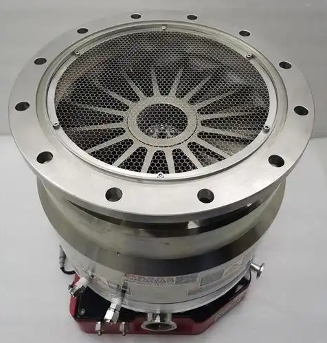
A turbomolecular impeller is the rotating blade assembly inside a turbomolecular pump that transfers momentum to gas molecules to generate high and ultra-high vacuum. It operates at very high rotational speeds in the molecular flow regime, using precisely machined rotor and stator blade stages to compress and transport gas from the high-vacuum side towards the backing pump.
In practice, the turbomolecular impeller is the core functional component that defines the pump’s performance in terms of pumping speed, compression ratio, gas handling capability, and ultimate pressure. Understanding its structure, operating principle, materials, and design parameters is essential for selecting, operating, and maintaining turbomolecular pumps in scientific and industrial applications.
Principle of Operation of a Turbomolecular Impeller
A turbomolecular impeller works on the principle of momentum transfer between rapidly moving blades and gas molecules. It is designed to operate in the molecular flow regime, where the mean free path of the gas molecules is comparable to or larger than the characteristic dimensions inside the pump.
Gas molecules enter the pump from the high-vacuum side and collide with the moving rotor blades. Because the blades move at high tangential velocities, these collisions impart a net momentum to the molecules in the direction of gas flow, pushing them towards successive stages and eventually to the exhaust connected to a backing pump.
The process can be summarized as follows:
- Gas molecules randomly enter the blade channels from the inlet.
- Molecules collide with the moving rotor surfaces and are “dragged” forward.
- Stator blades positioned after each rotor stage redirect the gas molecules so they can interact efficiently with the next rotor stage.
- Through multiple rotor-stator stages, gas is progressively compressed and transported to the outlet.
This mechanism differs fundamentally from positive displacement pumps. There are no pistons or valves; the entire process depends on kinetic interaction between high-speed blades and individual gas molecules, which is effective only at low pressures where molecular flow dominates.
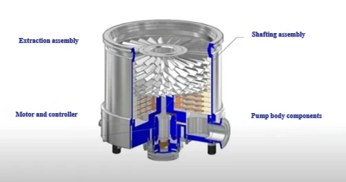
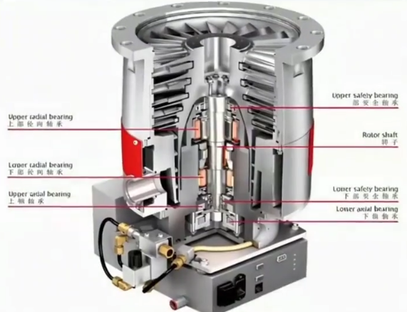
Construction and Main Components
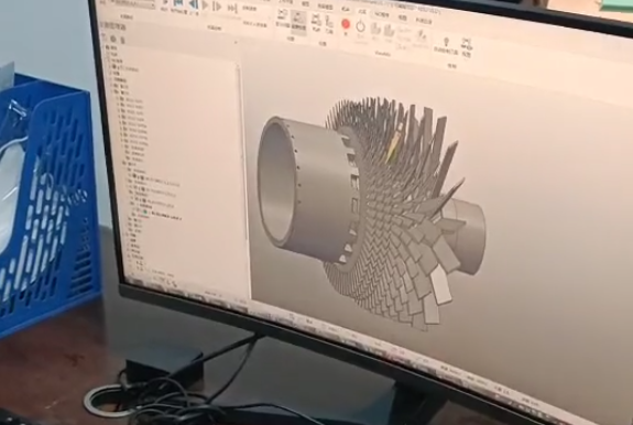
The turbomolecular impeller is not a single blade but a complex rotor assembly composed of many stages and support structures. Its construction must provide the required performance while maintaining mechanical strength and dimensional stability at very high rotational speeds.
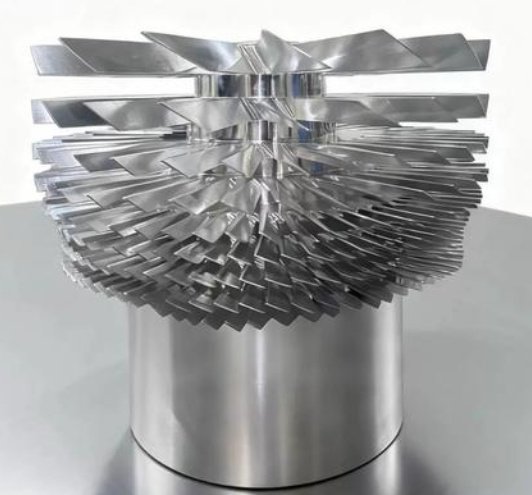
Rotor Stack
The rotor stack consists of multiple rotor disks with angled blades mounted on a central shaft. Each rotor disk forms one stage of the pump. Typical features include:
- Dozens to hundreds of thin blades per disk.
- Blades inclined relative to the direction of rotation to generate directed gas transport.
- Sequential stages with varying blade geometry tuned for different pressure ranges inside the pump.
The rotor stack is dynamically balanced to minimize vibration and stress. The shaft is supported by high-precision bearings, which may be mechanical, magnetic, or hybrid. The entire rotor assembly is housed in a vacuum-tight casing with closely spaced stator disks.
Rotor–Stator Stage Arrangement
In a turbomolecular pump, rotor and stator stages are stacked alternately. The stator is stationary and has blade channels aligned so that gas molecules leaving one rotor stage are directed optimally toward the next rotor stage. The impeller (rotor stack) works effectively only in combination with these stator stages.
Typical stage arrangement characteristics include:
Blade inclination and spacing: Carefully defined angles, spacing, and profile shapes to maximize momentum transfer and maintain high compression ratio.
Stage progression: Stages near the inlet are optimized for higher gas throughput at lower compression, while stages near the outlet are optimized for higher compression into the backing pressure.
Bearings and Drive
The impeller is driven by an electric motor integrated into or coupled to the rotor. This motor is typically a brushless DC motor or a high-frequency three-phase motor controlled by an electronic drive unit. The bearings hold the rotor in precise alignment:
Mechanical bearings: Often ceramic ball bearings lubricated by special greases or solid lubricants, sometimes supported by damping structures.
Magnetic bearings: Active or passive magnetic bearing systems that levitate the rotor, reducing friction and contamination, and allowing longer service intervals.
The design of the bearings and drive system directly influences the impeller’s allowable speed, lifetime, and vibration characteristics.

Materials Used in Turbomolecular Impellers
Materials for turbomolecular impellers must withstand high peripheral speeds, high centrifugal forces, and thermal loads, while maintaining ultra-high vacuum compatibility. Key material properties include high strength-to-weight ratio, minimal outgassing, and good corrosion resistance.
| Component | Common Materials | Main Reasons for Use |
|---|---|---|
| Rotor disks and blades | Aluminum alloys, titanium alloys, high-strength stainless steels | High strength at high speed, good machinability, acceptable mass, vacuum compatibility |
| Rotor shaft | Stainless steel, high-strength alloy steel | Mechanical robustness, fatigue resistance, dimensional stability |
| Stator disks | Aluminum alloys, stainless steel | Precision machining, structural stability, vacuum compatibility |
| Bearings (rolling elements) | Ceramic (e.g., Si3N4), high-grade steel | Low friction, high hardness, fatigue resistance |
| Permanent magnets (if used) | NdFeB, SmCo | High magnetic energy density, thermal stability |
| Housing in contact with rotor gas path | Stainless steel, aluminum | Structural integrity, vacuum sealing, corrosion resistance |
Surface treatments and coatings may be applied to improve wear resistance, reduce outgassing, or enhance corrosion resistance. Cleaning and preparation before assembly are critical to achieving low ultimate pressures.
Key Design Parameters and Typical Specifications
The performance of a turbomolecular impeller is determined by several design parameters. These parameters must be balanced to achieve the required pump characteristics while ensuring mechanical safety.
Rotational Speed
Typical turbomolecular impeller speeds range from about 24,000 rpm up to over 90,000 rpm, depending on the pump size and design. Small-diameter rotors usually run at higher speeds to achieve sufficient blade tip velocity.
The peripheral speed of rotor blades may reach several hundred meters per second. Rotor design, material strength, and bearing selection must accommodate the resulting centrifugal stresses and vibrations.
Blade Geometry
Blade geometry strongly affects pumping speed and compression ratio. Important geometric parameters include:
- Blade angle relative to the rotor circumference.
- Blade length and radial position.
- Blade spacing and channel height between rotor and stator blades.
- Thickness and profile shape of the blades.
Blades near the inlet often have geometry optimized for maximum capture probability of incoming molecules, while downstream blades focus more on achieving high compression against the backing pressure.
Pumping Speed and Compression Ratio
Pumping speed (often given in liters per second) indicates how quickly the pump removes gas from the connected vacuum chamber. The impeller’s surface area, blade geometry, and rotational speed all contribute to the effective pumping speed.
Compression ratio is the ratio of outlet pressure to inlet pressure for a given gas. Higher compression ratios require more stages and careful optimization of each stage’s blade angles and spacing. Light gases (such as hydrogen or helium) generally have lower compression ratios than heavier gases (such as nitrogen or argon) for a given impeller design.
Gas Throughput and Backing Pressure
The impeller must maintain performance over a range of gas loads. Gas throughput is limited by the capacity of the stages and the backing pump connected to the outlet. If backing pressure rises too high, compression and pumping performance at the high-vacuum side decrease.
Designers specify a maximum backing pressure above which the impeller cannot sustain the nominal compression ratio. The arrangement and number of stages, as well as the outlet geometry, are tailored to work with typical backing pumps such as rotary vane, scroll, or dry screw pumps.
| Parameter | Small Turbo Pump | Medium Turbo Pump | Large Turbo Pump |
|---|---|---|---|
| Nominal pumping speed (N2) | 20–80 l/s | 150–500 l/s | 700–2000+ l/s |
| Typical max speed | 60,000–90,000 rpm | 36,000–72,000 rpm | 24,000–48,000 rpm |
| Ultimate pressure range | ~10-8–10-9 mbar | ~10-8–10-10 mbar | ~10-8–10-10 mbar |
| Compression ratio (N2) | 107–109 | 107–1010 | 107–1010 |
These ranges are representative and depend on the specific impeller and pump design, gas type, and operating conditions.
Operating Mechanism in the Molecular Flow Regime
The effectiveness of a turbomolecular impeller depends on operating in the molecular flow region, typically below approximately 10-3 mbar, where gas molecules rarely collide with each other compared with collisions with solid surfaces.
Under molecular flow conditions:
1. Gas molecules follow mostly straight-line paths between collisions with rotor or stator blades.
2. The probability of a molecule colliding with a moving blade depends on blade geometry and orientation.
3. Each collision with a moving blade can be approximated as a momentum exchange, where the tangential component of blade velocity is transferred to the molecule.
The impeller is optimized to maximize the net flux of molecules from the inlet to the outlet. At higher pressures, where viscous or transitional flow dominates, the efficiency of this mechanism decreases, and the pump’s compression and pumping speed drop accordingly.
Role of the Turbomolecular Impeller in Complete Pump Systems
While the impeller generates the core pumping action, turbomolecular pumps are part of a broader vacuum system. The impeller must work in harmony with other components to achieve desired vacuum conditions and system reliability.
Interaction with Backing Pumps
Turbomolecular pumps are normally backed by mechanical pumps that maintain a sufficiently low exhaust pressure. The impeller design assumes a certain maximum backing pressure, above which gas compression becomes insufficient. Consequently:
- The impeller is not typically used as a stand-alone pump for rough vacuum.
- Appropriate backing pump capacity must be selected to match the gas flow and compression characteristics of the impeller.
Integration with Vacuum Chambers and Lines
The inlet of the turbomolecular pump (where the impeller faces the system) is usually connected directly or through short, large-diameter lines to the vacuum chamber. Conductance limitations in connecting pipes can reduce the effective pumping speed at the chamber. The impeller’s performance as measured at the pump inlet may not be fully realized at the chamber if these conductance effects are significant.
To minimize losses:
- Line diameter is increased as much as practical.
- Line length and bends are minimized.
- Internal surfaces are kept clean and outgassing is minimized.
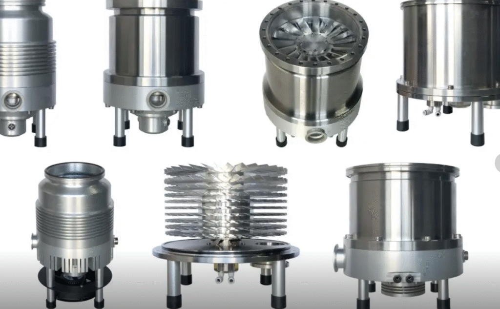
Common Applications of Turbomolecular Impellers
Turbomolecular impellers are used wherever clean, oil-free high vacuum is needed with fast pumping speed and high compression. They are central to many technologies and research activities that require controlled low-pressure environments.
Semiconductor and Thin-Film Processing
In semiconductor manufacturing, turbomolecular pumps provide high vacuum for processes such as physical vapor deposition, chemical vapor deposition, and etching. The impeller’s ability to sustain low base pressures with minimal contamination is critical for film quality and process uniformity.
Surface Science, Mass Spectrometry, and Analytical Instruments
Surface analysis techniques, electron microscopy, and mass spectrometry instruments depend on stable high vacuum or ultra-high vacuum to ensure accurate measurement and reduced background noise. Turbomolecular impellers provide the fast evacuation and low working pressures required to maintain instrument sensitivity and repeatability.
Research Laboratories and Large-Scale Facilities
In physics laboratories, particle accelerators, synchrotron beamlines, and fusion research devices, turbomolecular pumps with appropriately designed impellers maintain long sections of beamlines and vacuum vessels at pressures where particle–gas interactions are minimized.
Selection Considerations Related to the Impeller
When selecting a turbomolecular pump, many practical considerations are directly related to characteristics of the impeller and how it operates. Careful selection ensures that the pump meets performance requirements and operates reliably.
Required Pumping Speed at the Chamber
The nominal pumping speed of a pump is measured at the inlet. The actual effective pumping speed at the vacuum chamber depends on the conductance of the connecting lines. An impeller with higher rated pumping speed may be required if the connecting lines impose significant restrictions.
Gas Type and Composition
Turbomolecular impellers respond differently to gases with different molecular masses. Heavier gases are generally easier to compress, yielding higher compression ratios. Light gases, such as hydrogen and helium, are more difficult to compress, and specified compression ratios may be lower for these species.
Applications with significant light gas loads may require:
- Pumps with enhanced stage design for light gases.
- Larger impeller diameter or different blade geometry.
- Consideration of auxiliary pumping methods for very light gases.
Orientation and Mechanical Constraints
The mechanical design of the impeller and bearing system may impose orientation limitations. Some pumps allow any mounting orientation, while others specify preferred orientations based on bearing load and lubrication mechanisms. The selected pump must match the installation geometry to avoid excessive bearing stress or reduced lifetime.
Service Life and Maintenance Intervals
Impeller design influences bearing load, vibration, and stress distribution, which in turn affect maintenance intervals. Pump manufacturers specify recommended service intervals for bearing replacement or inspection. Factors such as operating speed, ambient conditions, and gas loads also influence these intervals.
Operational Considerations and Typical Issues
The turbomolecular impeller must be operated within specified limits to ensure safe and reliable performance. Practical considerations and typical issues include thermal management, vibration, contamination, and overload.
Start-Up and Shut-Down Behavior
During start-up, the impeller accelerates from standstill to full operational speed. The drive electronics control the ramp rate to limit mechanical stress and bearing load. Spin-up time can range from tens of seconds to several minutes, depending on pump size and design.
During shut-down, the rotor decelerates, sometimes under passive braking or controlled braking. In power failure situations, some pumps incorporate protection strategies to minimize the risk of backstreaming or shock loads on the rotor.
Vibration and Balancing
Because the impeller rotates at very high speed, even small imbalances can lead to significant vibration. The rotor is dynamically balanced during manufacturing, and the design of the impeller shaft and blades minimizes asymmetries. Improper handling, mechanical shocks, or contamination can disturb this balance, leading to increased noise, vibration, and bearing wear.
Contamination and Outgassing
Deposits on the rotor blades or stator surfaces can affect the molecular flow and momentum transfer process. Oil vapors, process by-products, and particulate matter may accumulate inside the pump if appropriate foreline traps, filters, or process control measures are not in place.
Contamination can lead to:
- Reduced pumping speed and compression ratio.
- Increased outgassing from heated deposits.
- Imbalanced rotor and increased vibration.
Clean system design, proper backing pump selection, and suitable process management practices help maintain clean operating conditions in the impeller region.
Overload and Overpressure
Operating a turbomolecular pump against high pressure or subjecting it to sudden pressure surges can overload the impeller. Gas loads beyond the specified limits can cause excessive heating, increased motor current, and reduced lifetime of bearings and electronics.
Typical protective measures include pressure interlocks, venting protocols, and control electronics that monitor current, speed, and temperature. Users should avoid opening the connected chamber to atmosphere while the impeller is running and must respect rated pressure limits.
FAQ About Turbomolecular Impellers
What is a turbomolecular impeller?
A turbomolecular impeller is a high-speed rotor with precision-shaped blades that accelerates gas molecules, enabling turbomolecular pumps to achieve high or ultra-high vacuum levels.
What industries use turbomolecular impellers?
Applications include semiconductor manufacturing, vacuum coating, mass spectrometry, particle accelerators, and ultra-high vacuum research.
What materials are used for turbomolecular impellers?
Common materials include stainless steel, aluminum alloys, titanium, and sometimes ceramic-coated metals to reduce weight, increase strength, and resist wear at high speeds.
What are the main types of turbomolecular impellers?
Impellers can be single-stage or multi-stage, with blade designs that are straight, twisted, or angled, depending on the application and required vacuum performance.
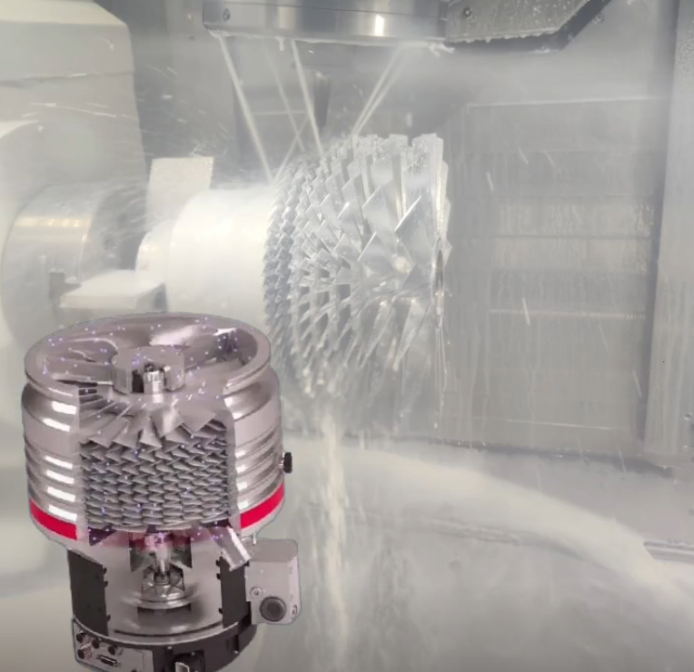
How are turbomolecular impellers manufactured?
Manufacturing methods include CNC machining, electrical discharge machining (EDM), precision grinding, and sometimes additive manufacturing for complex blade geometries.
