

Impellers and propellers are rotating devices used to impart energy to fluids. While they look similar in some applications, their functions, design parameters, and performance characteristics are distinct. Understanding these differences is essential when selecting equipment for pumps, fans, mixers, marine propulsion, and various industrial systems.
Fundamental Definitions
An accurate comparison starts with clear definitions of each device and the way they interact with fluids.
What is an Impeller?
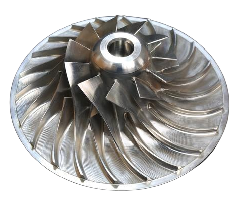
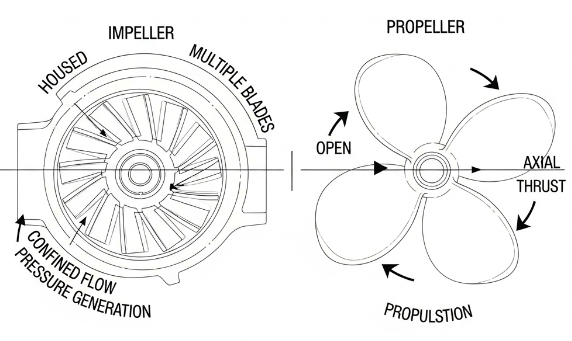
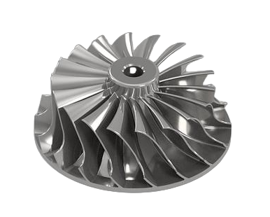
An impeller is a rotating component of a turbomachine designed to increase the pressure and/or velocity of a fluid. It is most commonly associated with pumps, compressors, blowers, and mixers. Impellers are typically enclosed or semi-enclosed within a casing that guides the fluid from inlet to outlet.
Typical functions include:
- Converting mechanical shaft power into fluid energy
- Raising fluid pressure in pumps and compressors
- Controlling flow direction (radial, mixed, or axial)
What is a Propeller?
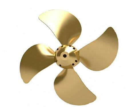
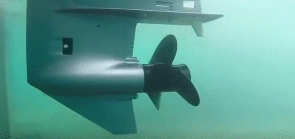
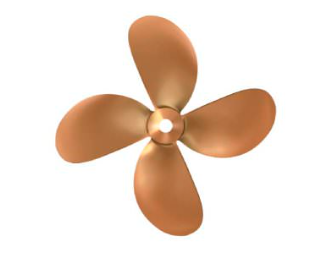
A propeller is a rotating device with blades arranged around a hub, primarily intended to produce thrust. Propellers operate in open fluid domains, without a fully enclosing casing, and are widely used in ships, boats, underwater vehicles, aircraft, cooling towers, and ventilation systems.
Typical functions include:
- Producing thrust to move a vehicle or fluid mass
- Inducing axial flow in open water or air
- Generating circulation in large tanks and basins
Shared Principles and Similarities
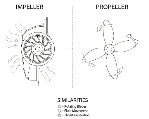
Despite their different applications, impellers and propellers share a number of fundamental characteristics.
Rotating Fluid Machinery
Both devices belong to the broader category of rotating fluid machinery. They use a rotating shaft to transfer mechanical energy into the fluid. The basic principles of angular momentum and conservation of mass apply irrespective of the specific geometry.
Use of Blades to Transfer Energy
Both impellers and propellers use blades to change the momentum of the fluid. As blades rotate, they exert forces on the fluid, accelerating it in a particular direction and thereby increasing its energy. Blade shape, angle, and spacing determine how efficiently this energy transfer occurs.
Dependence on Fluid Dynamics Laws
Both devices are governed by similar fluid dynamics rules:
- Bernoulli’s principle for relating velocity and pressure changes
- Continuity equation for volume or mass flow rate
- Euler’s turbomachinery equation linking torque, angular velocity, and energy transfer
Core Differences in Function and Role
The most important distinction is the primary role each device plays in a system.
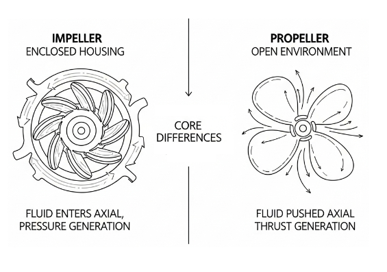
Energy Addition vs Thrust Production
An impeller primarily increases a fluid’s pressure and sometimes its velocity. It is usually part of a closed flow path inside a pump, compressor, or blower. The focus is on delivering a required pressure rise at a given flow rate.
A propeller primarily produces thrust by accelerating fluid mass in the opposite direction of desired motion. The goal is to move a vehicle or induce bulk fluid movement, not necessarily to generate high static pressure.
Operating Environment
Impellers typically operate inside casings or housings. This closed environment allows better control of flow paths and pressure rise. Propellers operate mostly in open environments such as open water, air, or large tanks without a fully enclosing casing.
Typical Performance Objectives
Performance targets differ significantly:
Impeller: Focus on head (pressure increase), flow rate, and hydraulic efficiency. System curves, net positive suction head (NPSH), and pressure losses are key design considerations.
Propeller: Focus on thrust, propulsive efficiency, and speed. For marine propellers, cavitation onset, thrust loading, and hull–propeller interaction are critical.
Design and Geometry Comparison
Impellers and propellers differ noticeably in blade shape, hub configuration, and containment. These differences reflect their design objectives and the way they interact with surrounding components.
| Aspect | Impeller | Propeller |
|---|---|---|
| Typical location | Inside casing or housing | Open fluid domain (water/air) |
| Blade count | Often higher (4–12 or more) | Lower (2–7 typical, often 3–5) |
| Blade orientation | Radial, mixed, or axial | Mainly axial with some skew and rake |
| Enclosure | Can be open, semi-open, enclosed | Usually open, may use nozzle or shroud |
| Primary goal | Increase pressure/head | Generate thrust/axial flow |
| Typical diameter range | From few cm to >1 m (industrial pumps) | From few cm (RC models) to several meters (ship propellers) |
Blade Shape and Profile
Impeller blades often use complex three-dimensional shapes to control radial and tangential fluid velocities, especially in mixed-flow and radial-flow pumps. They may include splitter blades and specific inlet/outlet angles to match design flow conditions and reduce losses.
Propeller blades are typically aerofoil or hydrofoil sections with defined chord length, thickness distribution, camber, and twist. The twist and pitch distribution ensure that each radial section operates at an appropriate angle of attack at design speed.
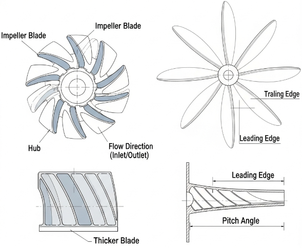
Hub, Shroud, and Casing
Impellers can be open (no front or back shroud), semi-open (one shroud), or closed (front and back shrouds enclosing the blades). Closed impellers are common in clean-liquid centrifugal pumps due to higher efficiency and better guidance of flow.
Propellers have a central hub to which blades are attached. The hub is streamlined to minimize drag. In some applications, a duct or nozzle surrounds the propeller (ducted propeller or Kort nozzle) to modify thrust characteristics, especially at low speeds, but the device remains fundamentally open compared to a fully cased impeller.
Types of Impellers and Propellers
Both categories contain several subtypes optimized for different flow patterns and duties.
Types of Pump and Fan Impellers
Common impeller types include:
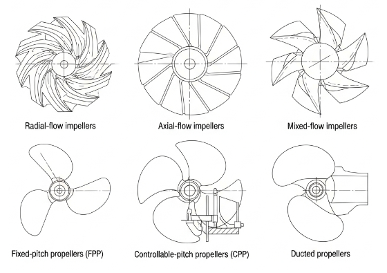
Radial-flow impellers: Fluid enters axially and exits radially. Suitable for high head, moderate to low flow rates. Used in many centrifugal pumps and some blowers.
Axial-flow impellers: Fluid enters and exits in the axial direction. Used in axial pumps and fans where large flow with relatively low head is required.
Mixed-flow impellers: Combine axial and radial components of flow, achieving intermediate head and flow capabilities. Suitable for drainage pumps, irrigation, and some chemical process pumps.
Impellers are also categorized by mechanical construction, such as:
- Open impellers: Better for solids-handling but often lower efficiency
- Semi-open impellers: Compromise between solids handling and efficiency
- Closed impellers: Higher efficiency with cleaner fluids
Types of Propellers
Common propeller configurations include:
Fixed-pitch propellers (FPP): Blade pitch is set during manufacturing and cannot be changed during operation. Widely used in small to medium vessels and many fans.
Controllable-pitch propellers (CPP): Blade pitch can be adjusted while running, allowing optimization of thrust and efficiency over a range of speeds and loads.
Ducted or nozzle propellers: Propeller enclosed by a stationary ring or duct to enhance thrust at specific operating conditions.
For fans and industrial mixers, propeller-type rotors may be categorized by blade shape (e.g., standard axial fan blades, paddle-type propellers, hydrofoil propellers) and are often selected based on flow, pressure, and mixing requirements.
Operating Principles and Flow Patterns
The way each device accelerates fluid and the resulting flow patterns are central to understanding their performance.
Impeller Operating Principle
In a typical centrifugal pump impeller, fluid enters near the axis (eye) of the impeller and is thrown outward by centrifugal force as the impeller rotates. The fluid gains tangential and radial velocity, which is partially converted into pressure in the volute or diffuser of the pump casing. This mechanism produces a pressure rise across the pump.
Key characteristics include:
- Significant pressure increase across the impeller
- Flow direction may change from axial to radial
- Strong interaction with casing geometry and diffusers
Propeller Operating Principle
Propellers work more like rotating wings. Each blade section produces lift that has a component in the direction of motion (thrust) and a component that contributes to torque. The propeller accelerates a column of fluid in the axial direction, and thrust is generated according to conservation of momentum.
Key characteristics include:
- Primary effect is axial acceleration of fluid
- Pressure increase is relatively small and localized
- Flow downstream is a high-velocity slipstream or wake
Performance Parameters and Metrics
Impellers and propellers are evaluated using different yet related performance metrics. Understanding these metrics is important for selecting and comparing equipment.
| Metric | Impeller (Pumps/Fans) | Propeller (Marine/Air) |
|---|---|---|
| Main output | Head (pressure rise) and flow rate | Thrust and advance speed |
| Efficiency | Hydraulic efficiency, overall pump efficiency | Propulsive efficiency, open-water efficiency |
| Key dimensionless numbers | Specific speed, flow coefficient, head coefficient | Advance coefficient, thrust coefficient, torque coefficient |
| Input variables | Speed, impeller diameter, fluid properties, suction/discharge conditions | Speed, diameter, fluid density, inflow speed (advance speed) |
Impeller Performance Indicators
For pumps and compressors, important indicators include:
Head (H): The energy per unit weight added to the fluid, typically measured in meters or feet. It characterizes the pump’s capability to overcome elevation differences and system losses.
Flow rate (Q): Volume or mass flow rate delivered by the pump. Usually expressed in m³/h, L/s, or gpm.
Specific speed (Ns): Dimensionless or dimensional parameter used to classify impellers based on their best efficiency point. It aids in selecting suitable impeller types (radial, mixed, axial) for a given head and flow combination.
Propeller Performance Indicators
For marine and aeronautical propellers, key indicators include:
Thrust (T): Force produced along the axis of rotation, measured in newtons or kilonewtons. It directly relates to vehicle propulsion and load-carrying capability.
Torque (Q): Rotational moment required to spin the propeller, used for power calculations and drive sizing.
Advance coefficient (J): Dimensionless parameter defined using inflow speed, propeller diameter, and rotational speed. It is used with thrust and torque coefficients to characterize propeller performance over a range of operating conditions.
Applications and Use Cases
The contrast between impellers and propellers is clear when examining where and how they are used in real systems.
Impeller Applications
Impellers are widely used in:
- Centrifugal pumps for water supply, wastewater treatment, irrigation, firefighting, and industrial fluids
- Process pumps in chemical, petrochemical, and food industries
- Compressors and blowers for gas handling and pneumatic conveying
- Fans for HVAC systems, industrial ventilation, and dust extraction
In many of these systems, the impeller is optimized for specific fluid properties (viscosity, solids content, corrosiveness) and system resistance curves.
Propeller Applications
Propellers are commonly used in:
- Marine propulsion for ships, boats, submarines, and unmanned underwater vehicles
- Aviation, including propeller-driven aircraft and drones
- Axial fans and cooling towers for moving large volumes of air
- Agitators and mixers where axial flow circulation is desired
In marine and aerospace applications, the interaction between propeller, hull or fuselage, and surrounding flow field strongly influences overall performance and noise characteristics.
Material Selection and Construction
Although both devices can share similar materials, the operating environment and failure modes often differ, influencing material choice.
Impeller Materials
Typical materials for impellers include:
Cast iron: Frequently used in water pumps due to cost-effectiveness and adequate mechanical properties for moderate conditions.
Stainless steel: Chosen for corrosive fluids, higher pressures, and hygienic applications such as food and pharmaceutical processing.
Bronze, duplex stainless steels, and superalloys: Used when corrosion, erosion, and high-stress conditions are combined, such as in seawater or chemical services.
Thermoplastics and composites: Employed for lower-pressure, corrosion-sensitive applications where weight reduction or chemical resistance is important.
Propeller Materials
Common materials for propellers include:
Marine bronze and nickel-aluminium-bronze: Widely used for ship propellers due to excellent corrosion resistance in seawater and good fatigue properties.
Stainless steels: Used for high-strength requirements, particularly in smaller high-speed propellers and in some underwater thrusters.
Aluminium alloys: Common in aircraft propellers and smaller marine propellers where weight reduction is critical.
Composite materials: Used in some marine and aeronautical propellers for weight savings, tailoring of stiffness, and corrosion resistance.
Installation, Mounting, and System Integration
The way impellers and propellers are installed and integrated into systems influences reliability and performance.
Impeller Integration
Impellers are mounted on shafts supported by bearings and sealed where the shaft passes through the casing. Mechanical seals, packing, or magnetic couplings are used depending on fluid type and leakage tolerance. Alignment with the motor or driver is critical to minimize vibration and bearing loads.
Casing and impeller clearances are tightly controlled to reduce recirculation and efficiency losses. Misalignment, wear, or incorrect clearances can significantly reduce performance and may lead to premature failure.
Propeller Integration
Marine propellers are mounted on shafts supported by stern tubes and bearings, often with flexible couplings and gearboxes between engine and shaft. Shaft alignment, vibration control, and hull clearance are critical to minimize noise, vibration, and cavitation.
In aircraft and fans, propellers are attached directly or via gearboxes to engines or motors, with attention to dynamic balancing, blade tracking, and structural integrity under cyclic loading.
Common Issues and Considerations
Both impellers and propellers face practical constraints linked to cavitation, vibration, maintenance, and efficiency over varying operating conditions.
Hydraulic and Propulsive Efficiency
Efficiency is a crucial factor because it directly affects energy consumption and operating cost. For impellers, efficiency is concentrated around a best efficiency point (BEP). Operating far from BEP can lead to recirculation, increased radial thrust, vibration, and accelerated wear.
For propellers, efficiency is highest at a specific advance coefficient. Operating outside the optimal range (for example, at heavily off-design vessel speeds or load conditions) can reduce thrust per unit power, increasing fuel consumption.
Cavitation Risk
Cavitation occurs when local pressure drops below the fluid’s vapor pressure, forming vapor bubbles that collapse in higher-pressure regions. Both impellers and propellers can experience cavitation, but the consequences and control methods differ.
In pumps, inadequate NPSH or high suction lift can cause impeller cavitation, leading to noise, vibration, pitting, and reduced performance. Proper inlet design, suction conditions, and impeller geometry are essential to minimize cavitation.
In propellers, cavitation is influenced by blade loading, vessel speed, submergence, and water properties. The onset of cavitation can cause noise, vibration, loss of thrust, and erosion of blade surfaces.
Wear, Corrosion, and Maintenance
Impellers in abrasive or corrosive services can experience erosion, pitting, and material loss, which alter blade profiles and reduce efficiency. Periodic inspection and material selection aligned with fluid properties are critical.
Propellers operating in seawater face galvanic corrosion and marine fouling, which can increase roughness and drag. Regular cleaning, coating, and cathodic protection are often applied to maintain performance.
How to Choose Between Impeller and Propeller
In many systems the choice is obvious, but in some fluid-handling or mixing applications, designers must decide whether a pump-type impeller or a propeller-type rotor is more appropriate.
Key Selection Criteria
Important questions include:
Required head versus flow: If the system primarily needs pressure increase in a closed circuit, an impeller within a pump or compressor is appropriate. If the goal is to move a large fluid volume with relatively small pressure difference in an open environment, a propeller or axial-flow impeller may be more suitable.
Operating environment: Closed piping circuits, pressure vessels, or sealed tanks typically use impellers. Open tanks, open water, and open-air applications more often use propellers.
Control requirements: Where variable operation over a wide range is necessary, controllable-pitch propellers or variable-speed drives on pumps may be considered. The method chosen affects mechanical complexity, cost, and maintenance.
Fluid properties: High viscosity, solids content, or aggressive chemistry may favor certain impeller designs or propeller shapes and materials. Matching the device to the fluid is essential for reliability and efficiency.
Summary of Similarities and Differences
Impellers and propellers are both rotating devices that transfer energy to fluids via blades, governed by similar fluid dynamics principles and reliant on careful design, material selection, and installation. However, their roles diverge significantly.
Impellers are mainly used to increase fluid pressure and control flow within enclosed systems, such as pumps, fans, and compressors, with emphasis on head, system curves, and hydraulic efficiency. Propellers primarily generate thrust and axial flow in open environments, focusing on propulsive efficiency, thrust, and interaction with surrounding structures.
Understanding these distinctions helps engineers and practitioners select the appropriate device, optimize system performance, and anticipate operational considerations such as cavitation, wear, and maintenance.
FAQ: Impeller vs Propeller
What is the difference between an impeller and a propeller?
An impeller is a component inside pumps or compressors that moves fluid by creating pressure and flow, while a propeller is used in watercraft or aircraft to generate thrust by moving air or water. Impellers are commonly used in centrifugal pumps, compressors, turbines, and turbomachinery for fluid transfer and pressurization. Propellers are commonly used in boats, ships, submarines, and airplanes to provide propulsion through water or air.
What shapes are typical for impellers vs propellers?
Impellers usually have curved or radial blades inside a cylindrical or conical casing, while propellers have blades extending outward from a central hub, designed for efficient thrust.
How do materials differ for impellers and propellers?
Impellers are typically made of stainless steel, bronze, or high-performance alloys to resist wear and corrosion inside pumps. Propellers often use aluminum, bronze, or composite materials optimized for strength and lightweight performance.
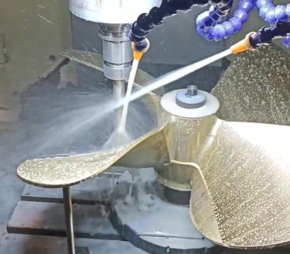
What are the manufacturing differences between impellers and propellers?
Impellers are typically CNC machined, cast, or 3D printed, depending on complexity, material, and performance requirements. Precision finishing such as grinding, polishing, and balancing is often needed. Propellers can be cast, forged, machined, or molded, often with post-machining processes like polishing, balancing, and surface coating to improve performance.
