

Blower impellers are the core rotating components in blowers and many types of industrial fans. They convert mechanical shaft power into fluid power by imparting velocity and pressure to air or gas. Understanding impeller basics, applications and machining methods is essential for engineers, designers, maintenance personnel and manufacturing specialists involved in air-handling and process equipment.
Fundamentals of Blower Impellers
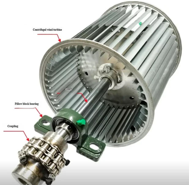
A blower impeller (often called a blower wheel or fan wheel) is a rotating assembly composed of blades (or vanes) attached to a hub and, in many designs, enclosed by shrouds or side plates. As the impeller rotates, it accelerates the gas and generates flow and pressure. Blowers are used where moderate to high static pressures and controlled flow rates are required, typically in HVAC, industrial ventilation, combustion air systems and process equipment.
From a fluid dynamic perspective, blower impellers operate by exchanging angular momentum with the working fluid. The geometry of the blades and the impeller diameter determine the amount of energy imparted to the gas, which directly influences the flow rate, pressure rise and efficiency. The impeller must also withstand mechanical stresses, vibration and wear while maintaining dimensional accuracy for stable operation.
Classification of Blower Impellers
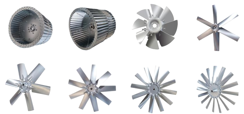
Blower impellers can be classified in several ways. The most common classification is based on the flow path and blade geometry. Each type has specific performance characteristics suitable for particular applications.
Radial and Centrifugal Impellers
Centrifugal blower impellers draw gas in axially at the center and discharge it radially. They are widely used for higher pressure requirements and a wide range of flow rates. Radial impellers typically include:
- Radial-bladed (straight radial blades)
- Forward-curved blades
- Backward-curved or backward-inclined blades
Radial-bladed impellers are robust and suitable for handling dust-laden or particulate-bearing gases. Forward-curved designs are compact and provide high flow at lower speeds with relatively low noise, widely used in HVAC and small blowers. Backward-curved impellers offer higher efficiency and better power control across the operating range, commonly used in industrial and process blowers.
Axial Impellers Used in Blowers
Although the term blower often refers to centrifugal machines, axial impellers are also used in some blower-type applications where large flow rates at relatively low static pressure are needed. Axial impellers move air mainly along the shaft axis with blade profiles similar to propellers or aerofoils. They are often selected for ventilation, cooling towers, and low-pressure process air systems with restricted installation space.
Mixed-Flow Impellers
Mixed-flow impellers combine features of centrifugal and axial types, producing both radial and axial flow components. They offer a compromise between high flow capacity and moderate pressure rise, with compact dimensions. Mixed-flow impellers are used where duct routing, footprint constraints and performance requirements point to intermediate characteristics between axial and centrifugal designs.
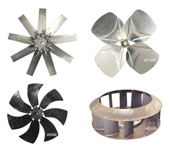
Open, Semi-Open and Shrouded Impellers
Based on blade enclosure, blower impellers can be:
- Open: blades are attached only to the hub, without side plates.
- Semi-open: blades attached to a hub and one side plate.
- Shrouded (closed): blades enclosed between two side plates or a side plate and a back plate.
Open impellers are easier to manufacture and clean, suitable for contaminated gas or when clogging is a concern. Shrouded impellers reduce leakage losses and are used when higher efficiency and better control of flow channels are required. Semi-open designs provide a compromise between accessibility and performance.
Key Design Parameters and Performance Characteristics
Impeller design is governed by aerodynamic and mechanical parameters that directly affect the blower performance. Correctly specifying and understanding these parameters helps achieve the desired flow, pressure and efficiency while ensuring mechanical reliability.
| Parameter | Typical Range / Description | Impact on Performance |
|---|---|---|
| Impeller outer diameter (D2) | 100–2000 mm (small HVAC to large industrial) | Larger diameter increases pressure and flow but requires more power and stronger structure. |
| Impeller width at outlet (b2) | Proportional to required flow | Wider impellers handle higher flow at similar speed; influences efficiency and size. |
| Blade outlet angle (β2) | Forward: β2 > 90°; Backward: β2 < 90° | Determines head-flow characteristics, power curve and efficiency. |
| Speed of rotation (n) | 500–3600 rpm (common industrial range) | Head ∝ n²; flow ∝ n; stresses and noise increase with speed. |
| Number of blades (Z) | Typically 8–64 (depending on type and size) | Affects slip factor, efficiency, noise and potential for clogging. |
| Specific speed (Ns) | Non-dimensional performance index | Used to classify impeller type and predict characteristic curves. |
| Static pressure rise | From a few hundred to several thousand Pa | Core design requirement for blower selection. |
| Flow rate | From <100 m³/h to >200,000 m³/h | Determines impeller size, width and operating speed. |
Blade Geometry and Flow Control
Blade geometry is one of the most influential aspects of performance. Critical geometric parameters include blade inlet and outlet angles, blade thickness distribution, curvature, leading edge shape, trailing edge cut and chord length. Accurate design controls the fluid incidence angle and relative velocity at the inlet and outlet, minimizing losses due to separation and recirculation.
Backward-curved blades typically provide higher efficiency and a stable power characteristic where input power peaks near the design point and drops as flow decreases. Forward-curved blades can be quieter and smaller but may exhibit rising power curves, requiring careful motor selection to avoid overload at higher flows.
Efficiency Considerations
Efficiency is strongly influenced by:
- Profile losses due to boundary layer and separation on blade surfaces.
- Leakage losses at blade tip, shroud clearances and side gaps.
- Disc friction losses from rotating surfaces in the casing.
- Incidence losses due to mismatch between flow angle and blade angle.
Maintaining tight manufacturing tolerances, smooth surfaces in flow paths and consistent blade geometry reduces losses and improves blower energy efficiency. In many installations, energy consumption over the service life far exceeds initial equipment cost, so efficient impeller design and precise machining are technically and economically significant.
Materials and Surface Treatment of Blower Impellers
Material selection depends on operating temperature, gas composition, particulate content, required mechanical strength and cost targets. Common materials include carbon steels, stainless steels, aluminum alloys and engineering plastics, as well as specialty alloys for corrosive environments.
Metallic Materials
Carbon steel is widely used for general-purpose blowers, offering good strength, weldability and cost-effectiveness. Stainless steels (such as 304, 316) are chosen for humid, mildly corrosive or hygienic applications including food processing and certain chemical processes. For elevated temperatures or aggressive chemicals, higher-grade stainless steels or nickel-based alloys may be required.
Aluminum alloys are used where low weight is critical and the gas is non-abrasive and non-corrosive. They are common in small HVAC blowers and portable equipment. However, aluminum has lower fatigue strength and lower maximum temperature capability compared to many steels.
Non-metallic Materials
Engineering plastics and composite materials may be used in small blowers, corrosion-sensitive environments or where weight and noise reduction are important. Glass-fiber reinforced polymers or other composites can offer good corrosion resistance and acceptable strength within moderate temperature limits.
Surface Treatment and Coatings
Surface treatment improves resistance to corrosion, erosion and fouling, and can aid cleaning. Typical treatments include:
- Protective paints and epoxy coatings for mild corrosion and general protection.
- Galvanizing or zinc-rich coatings for steel in certain outdoor or humid environments.
- Hardfacing or wear-resistant coatings in dusty or abrasive gas streams.
Proper surface preparation and coating thickness control are important for uniform protection and to avoid imbalance due to uneven coating distribution.
Typical Industrial Applications of Blower Impellers
Blower impellers are used in a wide spectrum of installations. Application conditions drive the choice of impeller type, material and machining approach.
HVAC and Building Ventilation
In heating, ventilation and air-conditioning systems, blower impellers are used in air handlers, roof fans, duct blowers and packaged units. Forward-curved and backward-curved centrifugal impellers dominate because of their compact size, relatively low noise and ability to generate required static pressure in ducted systems. Material selection usually prioritizes cost, with mild steel or galvanized steel commonly used.
Industrial Ventilation and Dust Collection
Industrial plants rely on blowers to remove fumes, smoke, dust and vapors. Radial and backward-curved impellers are frequently selected for their robustness and ability to handle higher dust loading. For dust collection, impellers may be designed with thicker blades, fewer passages and open or semi-open configurations to minimize clogging and facilitate cleaning.
Combustion Air and Process Gas Blowers
Boilers, furnaces, kilns and many process heaters require combustion air blowers. These impellers must provide stable flow and pressure across a wide operating range and withstand elevated temperatures. Material and balancing quality are important to avoid vibration that can affect burner stability and mechanical life.
Pneumatic Conveying and Material Handling
In pneumatic conveying systems, blowers generate the air flow that transports bulk solids through pipelines. Impellers may encounter erosive conditions due to particle impacts and may be designed with wear-resistant materials or coatings. The impeller geometry is optimized to maintain adequate conveying velocity while minimizing energy consumption and wear rate.
Cooling and Exhaust Systems
Impelled blowers are used in equipment cooling (e.g., electrical cabinets, machinery enclosures) and exhaust systems for process or engine gases. Selection focuses on ensuring sufficient flow to control temperature and remove contaminants, with compactness and noise often being secondary considerations.
Core Machining and Manufacturing Methods for Impellers
Impeller manufacturing combines forming, machining, joining and finishing operations. The specific sequence depends on impeller size, material, design complexity and production volume. Machining methods must achieve the required dimensional accuracy, surface finish and balance while maintaining structural integrity.
Casting and Subsequent Machining
For larger or complex impellers, casting is widely used. The process typically involves pattern making, mold preparation, metal pouring and solidification, followed by removal of risers and gates. After casting, critical surfaces such as bore, hub faces, reference diameters and mounting surfaces are machined.
Common machining operations on cast impellers include:
- Turning of hub and shroud outer diameters.
- Boring and reaming of shaft bore to achieve precise fit.
- Facing of side plates for flatness and parallelism.
- Drilling and tapping of key or set-screw holes.
Where blades are integrally cast, additional machining may be needed to clean up leading and trailing edges or remove casting draft that affects aerodynamic performance.
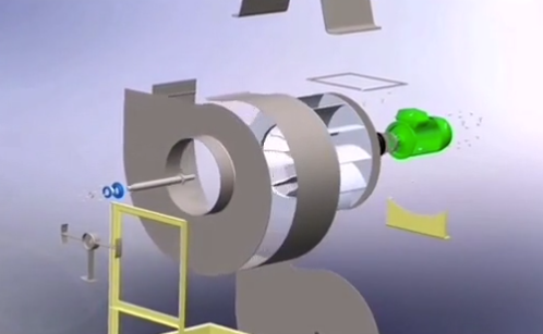
Fabricated Welded Impellers
Many industrial impellers are fabricated from plate and sheet, cut and formed into blades, hubs and shrouds and then welded together. This approach is flexible, suitable for a wide range of sizes and allows material optimization.
Typical fabrication steps include:
1. Cutting plates and profiles (using laser, plasma, waterjet or shearing).
2. Forming blades using press brakes or rolling machines.
3. Machining the hub to accept the shaft and provide reference surfaces.
4. Welding blades to the hub and shrouds, often using fixtures for accurate alignment.
5. Post-weld machining to correct distortion, achieve final dimensions and prepare surfaces for balancing.
Welding procedures must limit distortion and residual stress. After welding, stress relief heat treatment may be used for thick or heavily loaded impellers before final machining.
CNC Machining of Blades and Hubs
CNC machining is employed for high-precision impellers or when complex three-dimensional blade shapes are required. It provides accurate control of blade geometry, which directly influences performance. CNC operations may be applied to solid billets or semi-finished castings and forgings.
Key CNC operations include:
- 3-axis or 5-axis milling of blade surfaces and shrouds.
- Turning of hubs and reference diameters on CNC lathes.
- Drilling and boring of shaft bores, keyways and bolt patterns.
Tool selection must consider material hardness, required surface finish and productivity. Tool paths are planned to maintain uniform stock removal, minimize machining forces on thin blades and control heat input to avoid distortion.
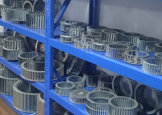
Sheet Metal Forming and Stamping
For small to medium-sized HVAC and appliance blowers, impellers are often manufactured using sheet metal stamping and forming. Blades and shrouds are stamped and then assembled by riveting, spot welding or other joining methods. This high-volume method is cost-effective and provides consistent geometry when tooling is properly designed and maintained.
Secondary machining may include sizing of the central bore, trimming of edges and creation of balancing holes. Because sheet metal impellers are relatively thin, precise forming and minimal runout are important to limit vibration and noise.
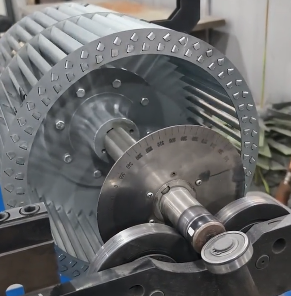
Balancing, Tolerances and Quality Control
Rotational balance and dimensional accuracy are critical to the reliable operation of blower impellers. Unbalance causes vibration, which can lead to bearing damage, increased noise and reduced service life. Quality control measures must verify that the impeller meets specified standards before installation.
Static and Dynamic Balancing
Static balancing ensures that the mass centerline coincides with the rotational axis when the impeller is stationary. It is suitable for slower-speed, small impellers. Dynamic balancing accounts for unbalance in two planes along the impeller width and is necessary for higher speeds and larger diameters.
Balance quality grades (such as those defined in ISO standards) specify the permissible residual unbalance based on speed and machine type. Balancing is typically performed on dedicated balancing machines. Corrections may be made by drilling material from heavy areas, adding balance weights or adjusting welded components. The balancing operation may be repeated after surface coating if coating thickness can significantly alter mass distribution.
Dimensional Tolerances and Runout
Critical tolerances in blower impellers include:
- Bore diameter and roundness for shaft fit.
- Keyway dimensions for torque transmission.
- Concentricity between bore and outer diameter.
- Axial runout of shrouds and side plates.
Excessive runout can create uneven tip clearances and contribute to noise, efficiency loss and contact between impeller and housing. Inspection methods include dial indicators, coordinate measuring machines (CMM), bore gauges and surface roughness testers.
Non-destructive Testing and Material Verification
In critical applications, non-destructive testing (NDT) may be applied to detect surface or subsurface defects. Common methods include magnetic particle inspection for ferromagnetic materials and dye penetrant testing for non-ferrous materials. For high-consequence installations, ultrasonic testing or radiography may be used on thick sections and welds.
Material verification by spectroscopic analysis or hardness testing ensures that the correct material grade has been used and that heat treatment has achieved the desired properties.
Practical Considerations in Impeller Use
Engineering and maintenance teams often encounter recurrent issues related to blower impellers. Recognizing these pain points helps in selecting appropriate designs and machining methods.
Vibration and Premature Bearing Failure
Poor balance, excessive runout or asymmetrical wear can lead to vibration. Over time, this vibration increases bearing loads and may cause premature bearing or shaft failure. To mitigate this, impellers should be balanced to suitable grades, and any repairs (such as weld buildup or blade replacement) must be followed by rebalancing.
Erosion, Corrosion and Fouling
In dusty, corrosive or sticky gas streams, impellers can experience erosion of blade leading edges, corrosive pitting or fouling. These issues alter blade geometry, increase imbalance and reduce performance. Selecting appropriate materials, coatings and more open blade configurations for contaminated flows reduces these effects. Regular inspection and cleaning schedules are essential for maintaining performance.
Machining Constraints on Thin Blades
Thin sheet metal or light-gauge blades are susceptible to distortion during machining, especially under high cutting forces or thermal loads. Careful fixturing, optimized cutting parameters and appropriate tool selection are required to maintain dimensional accuracy. Where possible, forming operations are completed before final machining of critical reference surfaces, minimizing the need to machine flexible regions.
Best Practices for Design, Machining and Maintenance
Combining sound design with disciplined machining and maintenance leads to reliable blower operation and reduced lifecycle cost.
Design and Specification Practices
When specifying blower impellers, engineers should clearly define the operating point (flow, pressure, speed), gas properties (temperature, composition, particulate content) and mechanical constraints (space, shaft size, mounting). Providing realistic operating ranges enables selection of an impeller type with stable performance across expected conditions.
It is useful to define required efficiency and acceptable noise levels, especially in HVAC and building applications. Mechanical specifications should include balance quality grade, material, surface treatment and required inspection methods.
Machining and Fabrication Practices
Machining processes should follow controlled procedures covered by process plans, including:
- Defined reference surfaces to ensure consistent setup and alignment.
- Controlled heat input when welding or heavy machining to minimize distortion.
- Intermediate inspections to confirm critical dimensions before final finishing.
For CNC machined impellers, maintaining up-to-date tool libraries, correct tool offsets and validated CAM programs reduces the risk of geometric errors. Documented rework procedures ensure that any dimensional correction or repairs still maintain design intent.
Installation and Maintenance
Correct installation of the impeller on the shaft is essential. The bore and keyway must match the shaft dimensions, and tightening torques on hub clamping elements or set screws should follow manufacturer recommendations. Misalignment or improper mounting can introduce artificial unbalance.
Maintenance practices include routine visual checks for cracks, corrosion and fouling, periodic vibration analysis to detect early signs of imbalance or mechanical looseness and cleaning of impeller surfaces when deposits accumulate. When blades are repaired, rebuilt or coated, the impeller must be rebalanced before being put back into service.
FAQ About Blower Impellers
What is the difference between a blower impeller and a fan blade?
A blower impeller is a multi-blade, typically enclosed or semi-enclosed rotating assembly designed to generate both flow and measurable static pressure, often in ducted systems. It forms the core of centrifugal or mixed-flow blowers and usually includes a hub, blades and side plates. A fan blade, particularly in simple axial fans, is often a set of open blades mounted on a hub, primarily generating flow at low static pressure with more direct axial discharge. In practice, both are rotating elements that move air, but blower impellers are optimized for higher pressure rise and controlled flow in confined or ducted installations.
Why is balancing so important for blower impellers?
Balancing ensures that the mass distribution of the impeller is symmetrical around the axis of rotation. If an impeller is out of balance, centrifugal forces cause vibration that can damage bearings, loosen fasteners, increase noise and reduce service life of both the blower and connected equipment. At higher speeds, even small unbalances generate significant forces. Therefore, precision balancing according to appropriate quality grades is essential after manufacturing, after any major repair and, if necessary, after applying surface coatings.
Which types of impellers are best for dusty or particulate-laden air?
For dusty or particulate-laden air, radial-bladed and open or semi-open impeller designs are commonly preferred. These impellers have relatively simple, robust blades and clear flow paths that reduce the risk of clogging. They can tolerate erosion better than thin, tightly spaced blades. Material choice and optional wear-resistant coatings further improve durability in abrasive service. Proper housing design and maintenance access also help manage dust accumulation and extend impeller life.
Can an existing blower impeller be re-machined or repaired instead of replaced?
In many cases, a blower impeller can be repaired by welding cracks, rebuilding worn edges, replacing individual blades or re-machining critical surfaces. However, repairs must preserve the original geometry as closely as possible to maintain performance. After any structural repair, the impeller should be inspected for defects, checked dimensionally and dynamically balanced. For severely corroded or heavily eroded impellers, the cost and risk associated with repair may exceed that of replacement, particularly when the equipment is critical to plant operation.
