
Basic Concepts Related to CNC Machining
CNC machining (Computer Numerical Control machining) is a subtractive manufacturing process in which cutting tools remove material from a solid workpiece under the control of a computer program. It is widely used for precision metal and plastic parts in aerospace, automotive, medical, electronics, mold making and general machinery.
What Is CNC Machining
CNC machining converts digital instructions into machine movements. A CNC program, often written in G-code, defines tool paths, spindle speeds, feed rates and auxiliary functions. The machine’s control system interprets these instructions and drives servo motors, spindles, tool changers and other components to perform precise cutting operations.
Key features of CNC machining:
- High dimensional accuracy and repeatability
- Capability to process complex 2D and 3D geometries
- Automated operation with less dependence on operator manual skills
- Flexible switching between different parts through program changes
Common Types of CNC Machining
Several main cutting processes are commonly implemented on CNC machines:
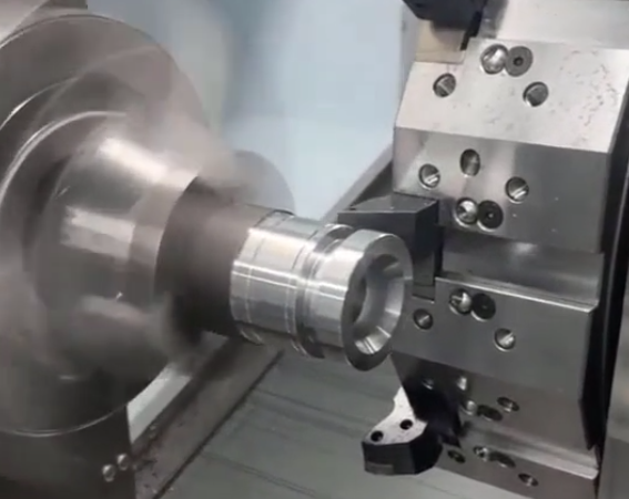
Turning (CNC lathe): Workpiece rotates, cutting tool feeds linearly. Suitable for shafts, sleeves, disks and other rotational parts. Typical operations: outer diameter turning, facing, grooving, threading, boring.
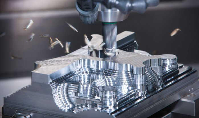
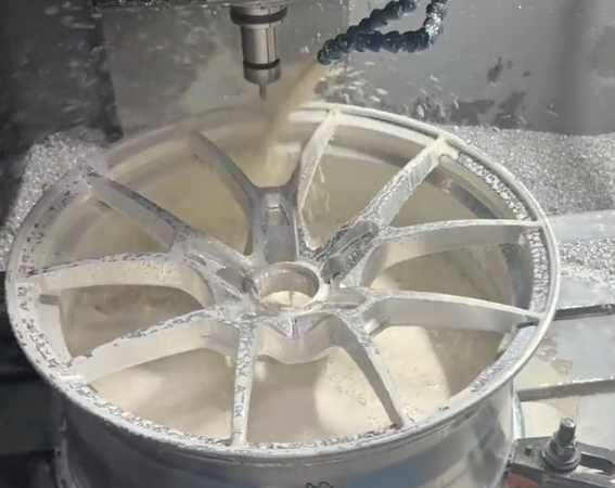
Milling (CNC milling machine / machining center): Cutting tool rotates, workpiece is usually fixed or moves linearly. Used for prismatic parts, cavities, pockets, slots, planes and 3D surfaces.
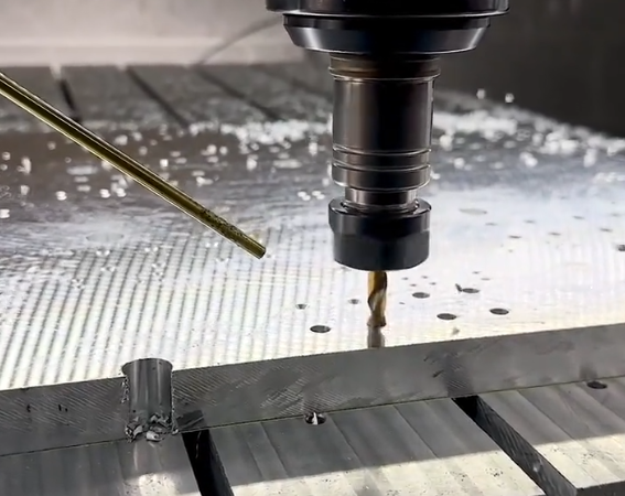
Drilling, Boring, Reaming: Hole-making operations. Drilling forms the initial hole, boring enlarges and improves accuracy, reaming enhances dimensional precision and surface finish.
Grinding: Uses an abrasive wheel for high-precision finishing. Commonly used for hardened steel, precision shafts, molds and tight-tolerance surfaces.
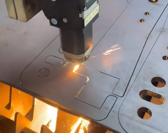
Other CNC-related processes include EDM (Electrical Discharge Machining), wire EDM and laser cutting, but in this guide the focus is on conventional cutting-based CNC machining.
Difference Between CNC and Manual Machining
Main differences include:
- Control method: Manual machines rely on human operation of handwheels and levers. CNC machines use servo-driven axes under numerical control.
- Accuracy and repeatability: CNC systems achieve stable accuracy (commonly ±0.01 mm or better for general machining centers) and consistent part-to-part quality, while manual machining depends heavily on operator skill.
- Complex geometry: CNC easily handles 3D freeform surfaces and multi-axis contours that are difficult or impossible manually.
- Productivity: CNC allows higher spindle speeds, optimized feeds, multi-tool operations and unattended machining, improving throughput and consistency.
- Setup and learning: CNC requires programming, tool offset setting and more upfront preparation, but simplifies repeated production once the process is established.
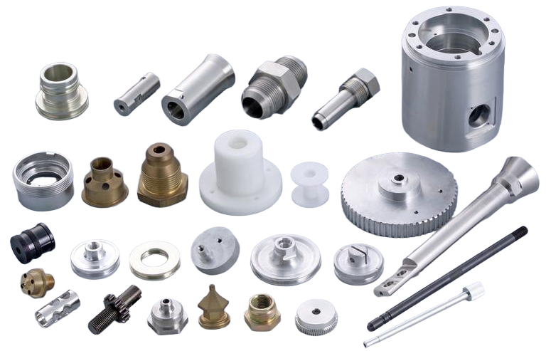
Products and Industries Suitable for CNC Machining
CNC machining is suitable for low to medium volume parts that require precision and good mechanical properties. Typical applications:
Aerospace: structural parts, brackets, housings, turbine components, landing gear elements.
Automotive: engine components, transmission parts, molds for plastic parts, fixtures.
Medical: orthopedic implants, surgical instruments, dental components.
Electronics: heat sinks, housings, connector blocks, fixtures for PCB assembly.
General machinery and automation: gear housings, machine frames, precision mechanical parts, custom tooling and jigs.
Advantages and Limitations of CNC Machining
Advantages:
- High dimensional accuracy and stable quality
- Flexible production for multiple part types
- Capability for complex 3D shapes and fine details
- Short lead time compared with many tooling-intensive processes
Limitations and considerations:
- Material is removed, so material utilization is lower than near-net-shape processes
- Very large parts or extremely hard materials may require special equipment or processes
- Tool reach and rigidity limit deep cavities and slender features
- Programming and setup time can be significant for very small batches
Key Points About CNC Machines and Control Systems
CNC machining performance depends strongly on the machine tool structure, the numerical control (NC) system and the supporting tooling. Understanding these aspects helps in selecting equipment, planning processes and troubleshooting.
Common Types of CNC Machine Tools
CNC Lathe: Performs turning operations. Can be 2-axis (X, Z), with optional C-axis for contouring and live tooling on some models. Applied to shaft and disk parts.
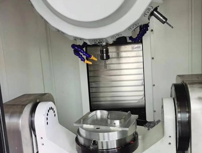
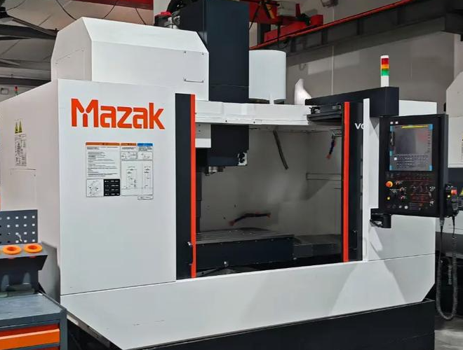
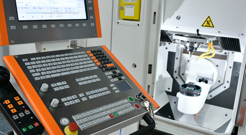
CNC Machining Center: Typically vertical (VMC) or horizontal (HMC). Equipped with automatic tool changer (ATC) and tool magazine. Used for milling, drilling, tapping and boring of prismatic parts.
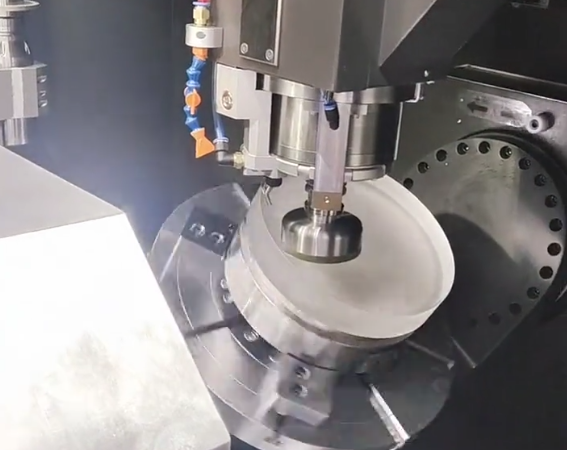
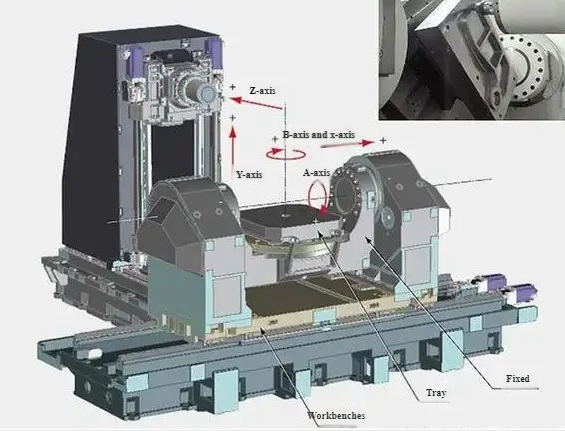
Five-Axis Machining Center: Adds two rotational axes to three linear axes. Allows multi-face machining in a single setup, improving accuracy and reducing setup time. Used for impellers, blades, complex molds and orthopedic implants.
Other machines include turning centers with milling function (turn-mill), gantry machining centers and high-speed graphite or mold machining centers.
Mainstream CNC Control Systems
Common industrial control systems include:
Fanuc: Widely used globally, stable, supports a wide range of machines, extensive parameter and macro capabilities.
Siemens: Common in Europe and advanced machining centers, strong in multi-axis and complex motion control.
Mitsubishi: Used in many Japanese and Asian machines, with reliable performance and good integration with machine drives.
Other controls: Heidenhain, Haas, OSP (Okuma), etc. Each control has its own interface and macro language, but all follow general G-code standards with manufacturer extensions.
Major Machine Components and Functions
Typical CNC machining center major components:
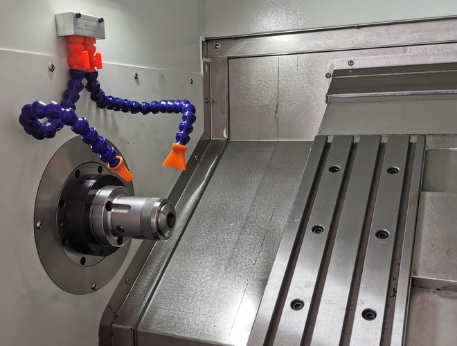
Main spindle: Provides rotation and power to the cutting tool. Key parameters include maximum speed (e.g., 8,000–24,000 rpm), power (kW) and taper type (BT, CAT, HSK).
Axes and guideways: X, Y, Z linear axes driven by ball screws or linear motors, guided by linear or box guideways. Determine travel ranges and rigidity.
Tool magazine and ATC: Hold multiple tools and perform automatic tool changes. Tool capacity often ranges from 16 to 120 tools.
Worktable: Supports the workpiece or fixtures. Important parameters include table size, maximum load and T-slot configuration.
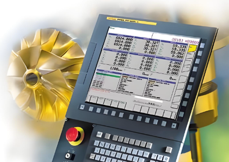
CNC control panel: Interface for program input, operation, monitoring and alarms.
Basics of Cutting Tools, Fixtures and Measuring Tools
Cutting tools: End mills, face mills, drills, reamers, taps, boring bars, threading tools. Tool material includes carbide, HSS, cermet and coated variants such as TiN, TiAlN, AlTiN.
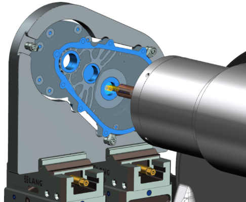
Fixtures: Workholding devices for stable and repeatable positioning. Examples: machine vises, chucks, modular fixtures, vacuum fixtures, angle plates, custom jigs.
Measuring tools: Calipers, micrometers, bore gauges, height gauges, gauge blocks, plug gauges, indicators and CMM for high-accuracy measurements.
Machine Accuracy and Stability
Key accuracy indicators include positioning accuracy, repeatability, straightness, squareness and spindle runout. Many general-purpose machining centers provide positioning accuracy around ±0.005–0.01 mm and repeatability around ±0.003–0.005 mm under standard conditions.
Stability is influenced by machine structure, thermal behavior, foundation, maintenance and ambient temperature. Warm-up cycles, coolant temperature control and periodic calibration help maintain consistent accuracy.
Overview of the CNC Machining Process Flow
CNC machining follows a systematic flow from design to delivery. Understanding each step ensures stable quality and predictable lead time.
General Flow from Drawing to Finished Part
The typical sequence:
1) Customer or design team provides 2D drawings and 3D models.
2) Manufacturing engineers perform process planning and define machining strategy.
3) Programmers create CNC programs using CAM or manual coding.
4) Setup personnel prepare machine, tools and fixtures.
5) First article is machined and inspected.
6) After approval, batch production starts.
7) Final inspection and delivery.
Drawing and 3D Model Preparation
Design input usually includes:
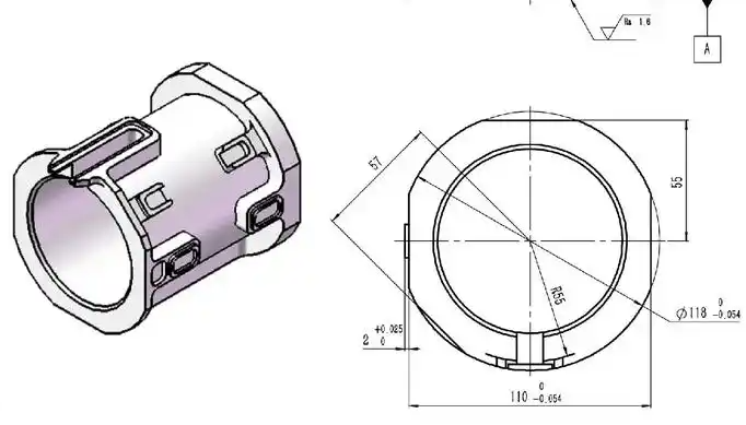
2D drawing: Contains dimensions, tolerances, GD&T (geometric dimensioning and tolerancing), surface roughness requirements, material specification and heat treatment requirements.
3D model: Describes the complete geometry. Used by CAM software to generate tool paths and check interferences.
For efficient machining, the design should avoid ambiguous dimensions, unnecessary tight tolerances and features that are too small relative to tool diameter.
Process Analysis and Process Planning
Process analysis includes evaluating:
- Machinability of material
- Selection of machine type and clamping strategy
- Sequence of operations (roughing, semi-finishing, finishing)
- Need for special tools, fixtures or intermediate heat treatment
Process planning outputs process sheets that specify operations, tools, cutting parameters, required fixtures and inspection checkpoints.
Programming: CAM Software and Manual Coding
CAM software such as Mastercam, NX (UG), Fusion 360, PowerMILL or SolidCAM converts 3D models into tool paths. The user defines tools, operations, cutting parameters and machining strategies, then post-processes the result into G-code compatible with the target control.
Manual programming is common for simple lathe operations or drilling patterns. The programmer writes G-code line by line, specifying coordinates, tool movements and auxiliary commands.
Trial Cutting, First Article Inspection and Batch Production
During trial cutting, the operator runs the program under careful monitoring, often with reduced feed override. Key settings such as work offsets (G54, G55 etc.), tool length and radius compensation are verified.
First article inspection compares critical dimensions and features against the drawing. If deviation occurs, adjustments may be made to offsets, tool paths, cutting parameters or process sequence.
Once the first article passes, batch production proceeds with consistent monitoring of tool wear, machine condition and process stability.
Quality Inspection and Shipping
After machining, parts may undergo deburring, cleaning, heat treatment or surface treatments (anodizing, plating, painting). Quality inspection includes in-process checks and final inspection. Conforming parts are packed and shipped according to handling and labeling requirements.
Process and Material Selection for CNC Machining
Material properties have a direct impact on tool selection, cutting parameters, achievable tolerance and surface finish. Proper process and material decisions reduce machining time, tool wear and risk of defects.
Common Metal Materials
Aluminum alloys: Examples include 6061-T6, 6082, 7075. Advantages: low density, good machinability, good thermal conductivity. Often used for housings, brackets, jigs and aerospace components.
Stainless steels: Examples include 304, 316, 17-4PH, 410. Offer corrosion resistance and moderate to high strength. Machinability varies; some grades cause built-up edge and tool wear if parameters are not optimized.
Carbon steels: Low-carbon steels (e.g., 1018, Q235) have good machinability; medium-carbon and alloy steels (e.g., 1045, 4140) provide better mechanical properties, sometimes requiring pre- or post-heat treatment.
Copper alloys: Pure copper, brass (e.g., C360) and bronze. Offer high conductivity or wear resistance. Some alloys are easy to cut; others may be gummy and require sharper tools and proper chip breaking.
Plastics and Composites in CNC Machining
Engineering plastics: POM (acetal), nylon, PEEK, PTFE, PC and others are machined for insulating parts, bearings, bushings, housings and medical components. They require sharp tools and attention to heat buildup to avoid deformation.
Composites: Carbon fiber reinforced plastics (CFRP) and glass fiber composites are machined for aerospace and sports equipment. They are abrasive to tools and can delaminate if feeds and tool geometry are not suitable.
Machining Characteristics and Considerations by Material
Key aspects include hardness, tensile strength, thermal conductivity and chip formation. Examples:
Aluminum: High cutting speeds, large chip volume, requires effective chip evacuation. Avoid built-up edge by using sharp, polished tools and appropriate coolant.
Stainless steel: Work hardens easily. Use lower cutting speeds, higher feed per tooth, positive rake tools and ample coolant.
Hardened steel: Often requires carbide or CBN tools and lower depths of cut. Grinding may be needed for final finishing.
Plastics: Thermal expansion and low softening point require lower spindle speeds and feed rates compared with metals of similar hardness, as well as minimal heat generation.
Design for Manufacturability (DFM) for Machined Parts
Design decisions strongly affect machining cost and feasibility. Typical DFM guidelines:
- Avoid excessively deep, narrow slots relative to cutter diameter
- Use standard hole sizes matching drill diameters where possible
- Provide corner radii consistent with standard end mill sizes, instead of sharp internal corners
- Minimize unnecessary tight tolerances and complex GD&T requirements
- Consider part orientation and number of setups when arranging features
Influence of Tolerance, Accuracy and Surface Roughness Requirements
Tighter tolerances and finer surface finishes require more stable processes, more precise machines, finer cutting parameters, more passes and frequent tool changes. For example:
Dimensional tolerance within ±0.02 mm may be achievable with standard machining centers and well-planned processes. Tighter tolerances such as ±0.005 mm may demand more rigid machines, stable thermal environment and dedicated fixturing.
Surface roughness: Ra 3.2 μm is typical for general milling, while Ra 0.8 μm or better may require finishing with lower feed, optimized tools and sometimes grinding or polishing.
Fundamentals of CNC Programming
CNC programming defines the movement and actions of the machine. Mastering basic G-code and M-code concepts helps in debugging, optimizing and communicating with the programming team.
Basic Concepts of G-Code and M-Code
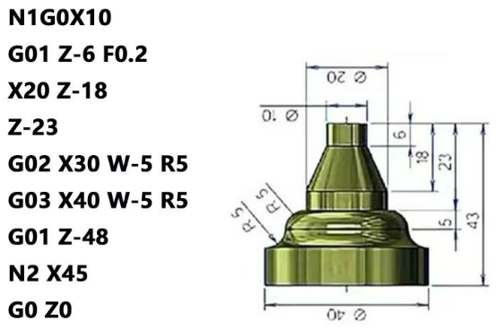
G-code: Preparatory functions that instruct the machine on motion mode and interpolation, such as G00 (rapid positioning), G01 (linear interpolation), G02/G03 (circular interpolation), G17/G18/G19 (plane selection) and G90/G91 (absolute/incremental programming).
M-code: Miscellaneous functions controlling non-motion actions such as spindle start/stop (e.g., M03, M04, M05), coolant on/off (e.g., M08, M09), program stop (M00), optional stop (M01) and tool change (e.g., M06).
Common Programming Commands and Format
A typical line of code (block) includes an optional block number (N), G-code, coordinates and feed/speed values:
N10 G01 X50.0 Y20.0 Z-5.0 F200.
Key command categories:
Motion commands: G00, G01, G02, G03, G33 (threading) etc.
Coordinate system commands: G54–G59 for work coordinate systems.
Cycle commands: G81–G89 for drilling, peck drilling and tapping cycles.
Compensation commands: G41/G42 for cutter radius compensation, G43/G49 for tool length compensation.
Coordinate Systems, Tool Compensation and Work Offsets
The machine uses different coordinate systems:
Machine coordinate system: Fixed reference used by the control for axis limits and homing.
Work coordinate system: User-defined origin, typically set on a part datum. Common codes: G54, G55 and others.
Tool offsets: Tool length and radius values stored in the tool table. Compensation is applied so the programmed path corresponds to the actual cutting edge position.
Differences Between 2.5-Axis, 3-Axis and 5-Axis Programming
2.5-axis: Simultaneous motion in two axes while the third axis is positioned at a fixed level; used for pockets and profiles with constant depth steps.
3-axis: X, Y, Z move simultaneously for 3D surface machining. Common in mold and die machining.
5-axis: Adds two rotary axes. Programming must account for tool orientation, rotary axis kinematics and potential singularities. It allows shorter tools, better surface quality and fewer setups for complex geometries.
CAM Software Overview
Mastercam: Widely used CAM package for milling, turning and multitask machines, with strong toolpath libraries.
NX (UG): Integrated CAD/CAM/CAE environment suitable for large enterprises and complex products.
Fusion 360: Cloud-connected CAD/CAM platform, suitable for small to medium workshops and prototyping.
Most CAM systems support post-processing to generate control-specific G-code and provide simulation capabilities.
Program Simulation and Collision Checking
Simulation reproduces tool motion, tool changes, fixtures, workpiece and machine limits in virtual space. It helps detect:
- Tool-workpiece collisions
- Tool-holder-fixture interference
- Overtravel beyond machine axes limits
- Unexpected rapid moves and wrong approach paths
Using simulation reduces risk to machines, tools and workpieces, especially in multi-axis or high-value parts.
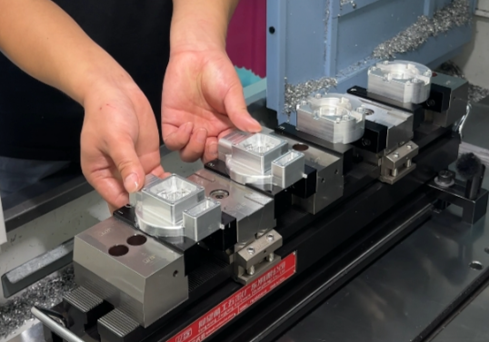
Fixture and Workholding Strategy Design
Effective workholding is essential to maintain part accuracy, reduce cycle time and ensure safe machining. Poor fixturing is a common source of dimensional error, chatter and scrap.
Principles of Fixture Design
Main principles include:
Positioning: Locate the part consistently based on datums and functional surfaces. Use the 3-2-1 principle to restrict all six degrees of freedom.
Clamping: Apply clamping force in directions that prevent movement under cutting forces but do not excessively deform the part.
Stability and rigidity: Minimize overhangs and ensure solid contact surfaces. Select fixture materials and structures capable of absorbing cutting loads.
Standard and Custom Fixtures
Standard fixtures: Machine vises, three-jaw chucks, collet chucks, modular fixturing elements and locating pins. They are flexible and suitable for many parts.
Custom fixtures: Designed for specific parts or families of parts. They may include dedicated locating surfaces, clamping mechanisms, hydraulic or pneumatic systems, and integrated sensors.
Multi-Station and Automated Fixtures
Multi-station fixtures allow multiple parts to be machined in one cycle or permit one station to be loaded while another is being machined. This improves spindle utilization and reduces idle time.
Automated fixtures may use hydraulic or pneumatic clamping controlled by the CNC program, enabling consistent clamping force and faster setup.
Reducing Setups and Cumulative Error
Each repositioning of the part introduces potential alignment and datum transfer error. Strategies to minimize this include:
- Combining operations on multi-axis or turn-mill machines
- Designing fixtures that expose multiple faces in a single clamping
- Using precision locating features such as dowel pins and reference stops
Impact on Productivity and Consistency
Well-designed fixtures reduce non-cutting time, enable higher cutting parameters by improving rigidity, and improve part-to-part consistency. They also reduce operator dependence and make it easier to standardize processes across shifts and operators.
Tool Selection and Cutting Parameter Optimization
Cutting tools and parameters directly affect machining efficiency, surface quality and tool life. Systematic parameter selection reduces unexpected tool failure and dimensional drift.
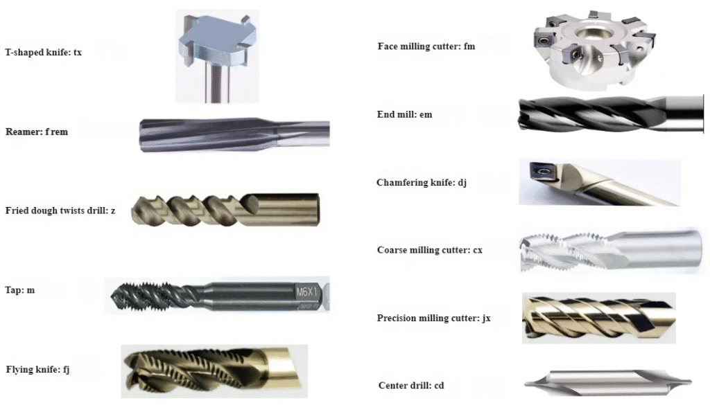
Types of Cutting Tools
Main tool categories:
End mills: For side milling, slotting, pocketing and contouring. Available in square, ball nose and corner radius designs.
Face mills: For high-efficiency surface milling. Often use indexable inserts.
Drills: For producing round holes. Can be twist drills, indexable drills or deep-hole drills.
Taps: For internal threads. Require appropriate hole size, lubrication and feed synchronization.
Boring tools: For enlarged and precise holes with tight tolerances.
Tool Materials and Coatings
Tool materials include HSS for general low-speed cutting and carbide for high-speed cutting and harder materials. CBN and ceramic tools are used for hardened steels and high-temperature alloys.
Common coatings: TiN, TiCN, TiAlN, AlTiN and DLC. Coatings increase hardness, reduce friction, improve heat resistance and extend tool life when properly matched to the material and cutting conditions.
Setting Spindle Speed, Feed Rate and Depth of Cut
Cutting parameters are usually determined by recommended ranges from tool manufacturers, material properties and machine capabilities:
| Material | Tool Type | Cutting Speed vc (m/min) | Feed per Tooth fz (mm/tooth) | Radial Depth ae (mm) | Axial Depth ap (mm) |
|---|---|---|---|---|---|
| Aluminum alloy | Carbide end mill Ø10 | 200–600 | 0.05–0.15 | 3–8 | 5–15 |
| Carbon steel (~180 HB) | Carbide end mill Ø10 | 120–220 | 0.03–0.10 | 2–6 | 3–10 |
| Stainless steel (austenitic) | Carbide end mill Ø10 | 80–160 | 0.03–0.08 | 1–4 | 2–8 |
Actual values should be adjusted based on machine rigidity, tool holding, coolant condition and required surface quality.
Recommended Parameters by Material Type
Aluminum: High cutting speed, moderate to high feed per tooth, larger radial and axial depths when machine rigidity allows.
Stainless steels: Lower speeds, moderate feeds, smaller radial engagement to avoid excessive heat and work hardening.
Hardened steels: Use coated carbide or CBN tools, relatively low speeds and carefully controlled depth of cut to minimize tool shock.
Tool Life Management and Wear Identification
Tool wear manifests as flank wear, crater wear, chipping and built-up edge. Regular inspection and tool life tracking reduce sudden breakage. Common methods:
- Count machined parts per tool and set limits based on experience
- Monitor spindle load and abnormal vibration as indicators of wear
- Schedule preventive tool changes before critical dimensions drift
Cutting Fluid Selection and Use
Cutting fluids serve to cool, lubricate and flush chips. Types include water-soluble emulsions, semi-synthetic and synthetic coolants, as well as straight cutting oils. Selection depends on material, process and environmental requirements.
Proper concentration, filtration and regular maintenance of cutting fluids reduce corrosion, odor, health concerns and instability in machining performance.
Surface Quality and Dimensional Accuracy Control
Ensuring that parts meet dimensional and surface finish requirements is central to CNC machining. This involves managing machine factors, cutting parameters, tooling and environmental conditions.
Dimensional Accuracy and Geometric Tolerances
Dimensional accuracy is determined by deviations from nominal dimensions, while geometric tolerances control form, orientation, location and runout. Examples are flatness, parallelism, position tolerance and total runout.
Stable fixture design, proper tool selection, calibrated machines and controlled thermal conditions all help maintain geometric accuracy.
Factors Affecting Surface Roughness
Surface roughness is influenced by feed per tooth, tool nose radius, tool path strategy, tool wear, machine vibration and material properties. Roughing operations normally prioritize material removal, while finishing operations prioritize surface quality with lower feed, smaller depth of cut and sharper tools.
Multiple Finishing Passes and Allowance Control
To achieve a consistent final dimension, process planning often leaves a uniform machining allowance for finishing. Typical practice is to leave a radial allowance of 0.2–0.5 mm for finishing passes in milling and a smaller allowance for grinding or high-precision finishing.
Multiple finishing passes may be used to reduce residual stress and improve surface consistency in critical areas.
Influence of Thermal Expansion and Tool Deflection
Thermal expansion of both the workpiece and the machine can influence dimension, especially over long machining cycles or when removing large amounts of material. Strategies:
- Warm-up cycles for machines before high-precision work
- Coolant temperature control and stable ambient temperature
- Symmetrical material removal to balance internal stresses
Tool deflection occurs when cutting forces exceed tool and holder rigidity. It is more pronounced with long overhang tools, small-diameter cutters and heavy side cuts. Reducing radial depth, using shorter tools and increasing tool diameter where possible mitigates deflection.
Reducing Chatter Marks, Burrs and Other Defects
Chatter marks and vibration-related patterns can stem from insufficient rigidity, unsuitable cutting parameters or tool imbalance. Improving clamping, adjusting spindle speed, reducing depth of cut and using variable pitch tools can help.
Burrs often form on edges and exit points of holes. Reducing feed, using sharper tools, optimizing cutting direction and adding deburring operations (manual or machine-based) are common solutions.
Automation and High-Efficiency CNC Production
Automation and process integration improve machine utilization, reduce labor and stabilize quality in CNC environments. The level of automation should match part volumes, complexity and investment capability.
Multi-Axis and Multi-Task Machine Tools
Multi-axis machines (e.g., 5-axis machining centers) and multi-task machines (turn-mill centers) combine multiple processes. They reduce setups, improve positional accuracy between features and shorten throughput time.
For example, a turn-mill center can complete turning of outer diameters, drilling of cross holes and milling of key slots in a single clamping, reducing datum transfer errors.
Automatic Tool Changers and Tool Management
Automatic tool changers (ATC) allow machines to perform complex sequences without manual intervention. Tool magazines can be managed by:
- Assigning fixed tool locations for frequently used tools
- Tracking tool life by program counters and tool usage history
- Using sister tools (duplicate tools) for continuous production
Automatic Loading/Unloading and Robotics
Robotic arms, gantry loaders and pallet systems can automatically load raw material and unload finished parts. This enables lights-out machining and extended unattended operation, subject to proper process stability and monitoring systems.
Flexible Manufacturing Systems and Line Planning
Flexible Manufacturing Systems (FMS) integrate multiple machine tools, pallets, tool storage and centralized control. They can dynamically schedule jobs, balance workload and adapt to mix changes with minimal manual intervention.
Effective line planning considers machine capacities, changeover frequency, fixture and tooling commonality, and inspection strategy.
Strategies for Small Batch vs High-Volume Production
Small batch, high-mix: Emphasize flexible fixtures, standard tooling, efficient setup procedures and robust generic programs. CAM templates and modular fixturing help reduce preparation time.
High-volume: Emphasize dedicated fixtures, optimized cycle times, tool life consistency and integrated automation. Process validation, SPC and preventive maintenance are critical to minimize downtime and scrap.
CNC Machining Quality Inspection and Control
Systematic inspection and process control ensure that parts meet requirements and deviations are detected early. Quality control integrates measuring methods, sampling plans and data analysis.
Use of Conventional Measuring Tools
Common hand-held tools:
Vernier and digital calipers: Versatile, typically accurate to ±0.02 mm. Used for general dimensions.
Micrometers: Provide higher accuracy, commonly ±0.005 mm, for critical diameters and thicknesses.
Plug gauges and thread gauges: For checking hole and thread compliance to nominal sizes and tolerances.
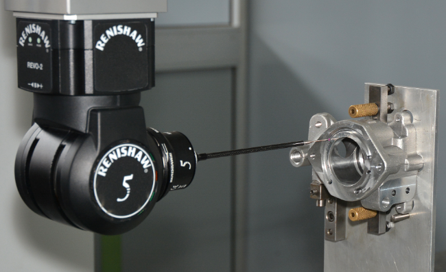
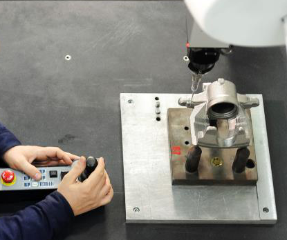
Coordinate Measuring Machines (CMM) and Inspection Programs
CMMs measure parts using tactile probes or non-contact sensors. They reference a defined coordinate system and allow precise evaluation of GD&T characteristics such as position, profile and runout.
Inspection programs can be created offline based on CAD models, similar to CAM toolpath generation. This reduces programming time and ensures consistent inspection routines.
First Article, In-Process and Final Inspection
First article inspection: Comprehensive verification of the first part in a production run, checking most or all critical features.
In-process inspection: Performed during batch production at defined intervals, focusing on key dimensions sensitive to tool wear or thermal drift.
Final inspection: Conducted before shipment. May be 100% or based on sampling, depending on customer requirements and internal rules.
Application of SPC (Statistical Process Control)
SPC uses statistical methods such as control charts to monitor process variability. Selected critical dimensions are measured on a sample basis, and their values are plotted over time. When trends or out-of-control conditions appear, corrective actions are taken before nonconforming parts accumulate.
Nonconformance Analysis and Corrective Actions
When a dimension is out of tolerance, the analysis should consider tool wear, offset settings, fixture movement, thermal influence, programming errors and material variation. Corrective actions may include adjusting offsets, replacing tools, revising parameters or modifying fixturing or process steps.
Cost, Lead Time and Project Management in CNC
CNC projects must balance technical feasibility, cost and delivery time. Transparent cost breakdown and effective communication minimize rework and delays.
Cost Structure of CNC Machining
Typical cost components:
- Material cost: Raw material, allowance for cutting and yield loss
- Machine time: Charged per hour based on machine type, depreciation and overhead
- Tooling cost: Cutting tools, fixtures and measuring tools, including wear and replacement
- Labor cost: Programming, setup, operation, inspection and handling
Evaluating and Quoting CNC Projects
Quoting requires estimation of machining time, setup time, programming effort, material cost and any external processes (heat treatment, surface finishing). Part complexity, tolerance level and order quantity all influence unit price.
Planning Machining and Delivery Lead Times
Lead time includes process planning, programming, procurement of material, fixture or tool manufacturing, machine availability, machining, inspection and external treatments. Clear scheduling and resource allocation prevent bottlenecks at critical machines or inspection areas.
Reducing Rework and Scrap Rates
Practical methods:
Standardized work instructions for setup and measurement procedures.
Documented first article approval and controlled program version management.
Clear identification of datums and critical features on drawings and process sheets.
Regular review of quality issues and feedback into process improvements.
Communicating with Customers on Drawings and Design Changes
Effective communication includes clarifying missing or conflicting tolerances, surface finish requirements, material specifications and heat treatment conditions. Changes should be documented in revision-controlled drawings and records to prevent confusion.
Safety Standards and Machine Maintenance
Safe operation and regular maintenance protect personnel, equipment and production stability. Safety and maintenance are integral parts of CNC management.
Safety Practices in CNC Machining Environments
Key safety points:
- Wear appropriate personal protective equipment (PPE) such as safety glasses and protective footwear
- Ensure machine doors and guards are closed during machining
- Do not reach into the machining area while the spindle or axis is moving
- Use proper lifting methods and tools for heavy workpieces and fixtures
Daily Checks and Routine Maintenance
Daily checks may include verifying coolant level and concentration, checking lubrication systems, cleaning chips, confirming air supply pressure and ensuring emergency stops and interlocks function properly.
Routine maintenance schedules may specify periodic replacement of filters, inspection of belts, cleaning of electrical cabinets and alignment checks.
Preventive Maintenance and Basic Troubleshooting
Preventive maintenance reduces unplanned downtime and helps maintain accuracy. It involves planned inspections and replacement of wear components before failure.
Basic troubleshooting includes responding to alarms, checking power and air supply, verifying reference return status, inspecting tool clamping, fixture integrity and confirming program and offset settings.
Environmental Protection and Handling of Fluids and Chips
Coolants and cutting oils must be stored, mixed and disposed of according to regulations. Proper chip collection and segregation by material support recycling and reduces contamination risk.
Extending Machine Life and Preserving Accuracy
Important practices:
Use machines within rated load and travel limits.
Avoid repeated collisions, overtravel and overload conditions.
Perform periodic geometry calibration (e.g., ballbar tests, laser calibration) to track and correct changes in accuracy over time.
Common CNC Issues and Case-Based Analysis
Recurring issues in CNC machining often have systematic causes. Identifying patterns and applying structured problem-solving helps stabilize production.
Investigating Consistent Dimensional Deviations
When dimensions consistently deviate in one direction, consider:
Incorrect tool length or radius compensation values.
Thermal drift from machine or workpiece temperature changes.
Fixture flex or movement under cutting loads.
Program errors such as offset misuse or wrong coordinate systems.
Frequent Tool Chipping or Short Tool Life
Common reasons include excessive cutting speed or feed, insufficient rigidity, improper tool selection or incorrect application of coolant. Tools may also fail prematurely when machining hardened zones, interrupted cuts or heavily scaled surfaces without proper adjustments.
Poor Surface Finish and Roughness Problems
Causes may be dull tools, excessive feed rate, inappropriate cutter geometry, insufficient rigidity, chatter, incorrect coolant application or poor toolholder balance. Adjusting one factor at a time and monitoring effect helps identify the main contributor.
Abnormal Machine Vibration and Noise
Abnormal vibration or noise can be related to damaged spindle bearings, worn guideways, loose bolts, unbalanced tool assemblies or unsuitable cutting conditions. Early identification and maintenance prevent damage and further accuracy deterioration.
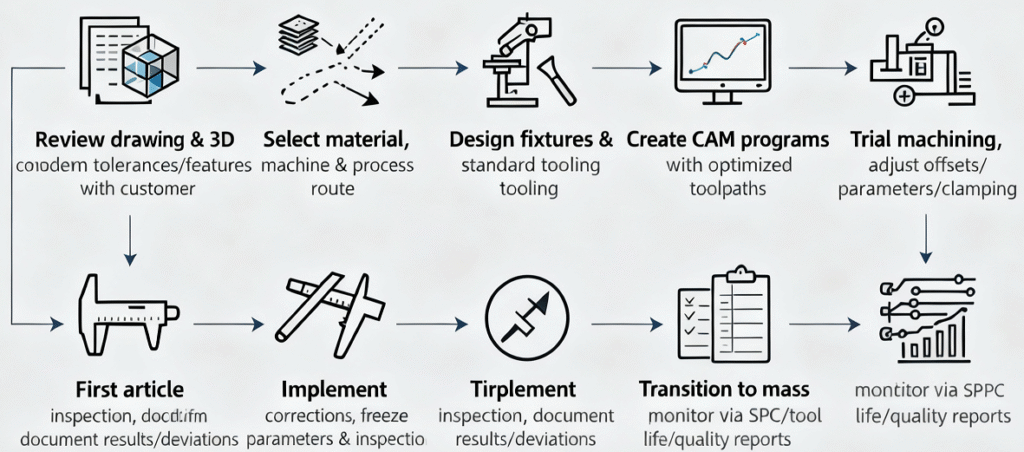
Case Study: From Drawing to Stable Mass Production
A typical implementation path for a new part:
1) Review drawing and 3D model, clarify unclear tolerances and functional features with the customer.
2) Select suitable material stock, machine type and general process route (sequence of operations).
3) Design fixtures and select standard tooling families to allow future variants.
4) Create CAM programs with toolpath optimization for both cycle time and stability.
5) Perform trial machining, adjusting offsets, cutting parameters and fixture clamping as needed.
6) Conduct thorough first article inspection and document measurement results and deviations.
7) Implement corrections, freeze process parameters and establish inspection plan and sampling frequency.
8) Transition to series production and monitor via SPC, tool life records and quality reports.
FAQ
What is CNC machining?
CNC machining, or Computer Numerical Control machining, is a manufacturing process in which pre-programmed computer software controls the movement of machinery and tools to produce precise parts from various materials such as metal, plastic, or wood. It allows for high accuracy, repeatability, and efficiency in producing complex components.
What are the advantages of CNC machining?
CNC machining offers high precision and consistency, reduced human error, the ability to produce complex geometries, faster production speeds, and scalability for both prototyping and mass production. It also improves material utilization and reduces waste compared to traditional manual machining.
What are the main types of CNC machining?
The main types of CNC machining include:
CNC Milling: Uses rotary cutters to remove material from a workpiece to create complex shapes.
CNC Turning: Rotates the workpiece against a stationary cutting tool to create cylindrical parts.
CNC Drilling: Automates precise hole drilling in various materials.
CNC Grinding: Uses abrasive wheels to achieve high precision surface finishes.
CNC Laser Cutting: Uses a laser to cut or engrave materials with extreme accuracy.
How do I choose the right type of CNC machining?
The choice of CNC machining method depends on factors like the material, desired precision, part complexity, production volume, and surface finish requirements. Milling is versatile for complex shapes, turning is ideal for cylindrical parts, and laser cutting is suitable for thin sheets or intricate patterns. Consulting with a CNC specialist ensures the best method is selected for your specific application.
Can CNC machining be used for both prototyping and mass production?
Yes, CNC machining is highly flexible and can be used for both prototyping and mass production. It allows rapid production of prototypes for testing and validation, and once a program is finalized, it can produce large quantities of parts consistently and accurately.
