
Sensor machining is a core process in the production of industrial, automotive, aerospace, medical, and consumer sensors. It determines mechanical robustness, dimensional accuracy, sealing performance, thermal behavior and, in many cases, the long‑term stability of measurement signals. This article provides a systematic, technical overview of machining methods, machinable sensor materials, tolerance and finish requirements, and cost structures for sensor components and assemblies.
Scope of Sensor Machining in Modern Devices
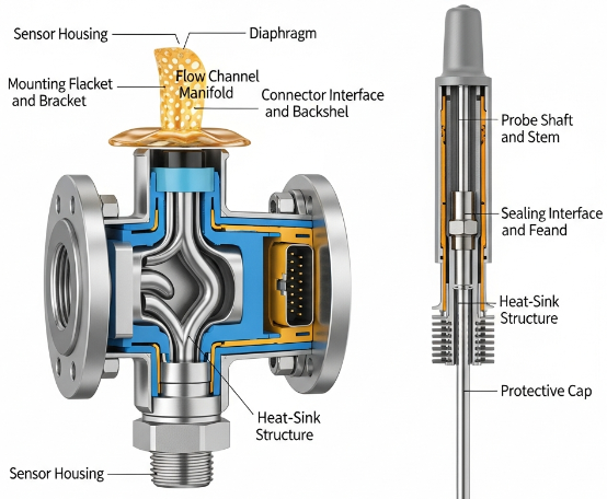
Machining in sensor manufacturing is not limited to housings. It covers a wide set of elements that directly affect sensor performance, mounting, and integration into higher‑level systems. Knowing which parts are typically machined helps clarify manufacturing priorities, inspection strategies and cost allocation.
Typical Machined Sensor Components
- Sensor housings and bodies
- Mounting flanges and brackets
- Probe shafts and stems
- Sealing interfaces and gland features
- Connector interfaces and backshells
- Flow channels and manifolds in flow or pressure sensors
- Heat‑sink structures for temperature or power sensors
- Protective caps, diaphragms and covers
These parts can be produced from metals, plastics, ceramics or composites depending on functional requirements such as operating temperature, required stiffness, corrosion resistance, pressure rating and electrical insulation.
Functional Requirements Driving Machining Choices
Key functional requirements that influence machining strategy include:
- Dimensional accuracy and repeatability for mounting geometry and internal alignment
- Surface finish in sealing zones, flow passages, and optical or magnetic interfaces
- Mechanical strength and fatigue resistance under vibration, shock, and pressure cycles
- Thermal conductivity or insulation requirements
- Chemical resistance to process media, fuels, oils, coolants and cleaning agents
- Electrical properties such as conductivity, shielding capability, or insulation
Choices of machining process, cutting tools, fixturing, and quality control methods are made to fulfill these requirements at the required production volume and cost level.
Core Machining Methods for Sensor Components
Most sensor bodies and mechanical parts are produced using subtractive manufacturing, with additional methods used for features that are difficult or inefficient to cut mechanically. This section covers common processes and their typical roles in sensor manufacturing.
Conventional Turning and Milling
Turning and milling are the backbone of machined sensor components, especially for metal parts and high‑precision housings.
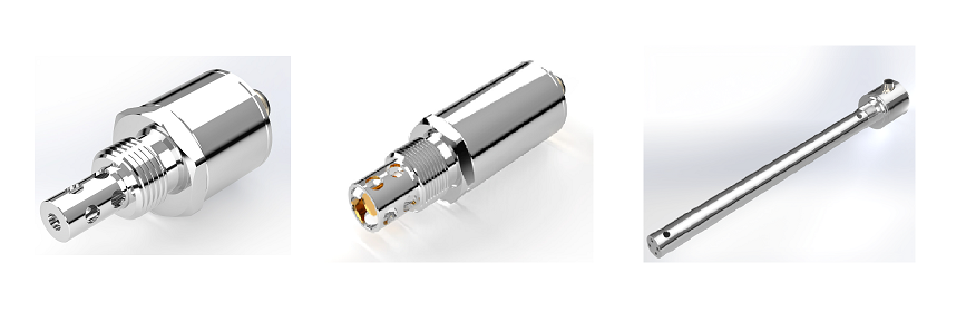
Turning is used for rotationally symmetric parts such as:
- Probe shafts and cylindrical housings
- Threaded process connections and pressure ports
- Shoulders and steps for sealing rings and O‑rings
- Concentric bores and counterbores for sensor inserts
Typical technical aspects:
For stainless steel or tool steel sensor bodies, CNC lathes are used with carbide inserts and appropriate coolant. Dimensional tolerances of IT6–IT7 are common without special finishing, tighter tolerances are possible with fine turning or subsequent grinding. Surface roughness for sealing faces is often Ra 0.8–1.6 μm; for general external surfaces Ra 3.2 μm is usually adequate.
Milling is applied when non‑rotational features are needed:
- Flat sealing faces and mounting flanges
- Keyed features and anti‑rotation flats
- Connector interfaces and cable exits
- Recesses for PCB assemblies or electronics
- Pockets and cavities in multi‑part housings
Three‑axis and four‑axis milling centers can handle most requirements. For highly integrated sensor packages with multiple angled surfaces or complex internal cavities, five‑axis machining is often used to reduce setups and maintain positional accuracy between features.
CNC Turning Centers and Mill‑Turn for Sensors
CNC turning centers with live tooling (mill‑turn) allow complete machining of sensor parts in a single setup. This is particularly relevant for:
- Small to medium sensor housings with both rotational and prismatic features
- High‑volume production where multiple setups would increase cost and error risk
- Compact designs with tight feature‑to‑feature tolerances
Mill‑turn machines combine turning, drilling, tapping, milling and even limited grinding in one cycle. This improves geometric relationships between critical features such as threaded ports, sensor element seats, alignment bores and connector interfaces.
Micro‑Machining for Miniaturized Sensors
As sensors shrink while maintaining functional complexity, micro‑machining techniques become important. Micro‑machining refers to cutting operations on small parts or features typically below 1 mm in size, using small‑diameter tools and high‑speed spindles.
Typical micro‑machining applications in sensors include:
- Micro bores for pressure transmission channels (e.g., 0.2–0.8 mm diameter)
- Small fluidic channels and mixing features in chemical and biomedical sensors
- Micro‑slots for strain gauges and thin‑film structures
- Miniature threads and alignment pins for MEMS packages
Micro‑machining requires rigid setups, precise tool holders, high spindle speeds (often > 30,000 rpm) and fine‑tuned feeds to avoid tool breakage. Tool run‑out and thermal expansion must be controlled to maintain tolerances often in the range of ±0.005–0.01 mm for critical features.
Grinding for High Precision and Surface Quality
Grinding is widely used where fine tolerances and high surface quality are required beyond what turning and milling can economically deliver. It is common for:
- Sealing surfaces in high‑pressure or vacuum sensors
- Bearing journals or guide surfaces in moving sensor mechanisms
- Flatness‑critical surfaces on reference plates or optical sensor bases
- Hard materials such as hardened steels or certain ceramics
Typical grinding results in:
- Dimensional tolerances down to ±0.002–0.005 mm
- Surface roughness Ra 0.1–0.4 μm, suitable for demanding sealing and sliding interfaces
- Improved roundness and cylindricity compared to general turning
While grinding increases cost and cycle time, it is often essential to guarantee long‑term stability in pressure sensors, flow meters, encoders and high‑accuracy displacement sensors.
Electrical Discharge Machining for Hard or Complex Parts
Electrical Discharge Machining (EDM) is a non‑contact process for cutting conductive materials using electrical discharges. It is particularly useful for:
- Hard materials that are difficult to machine conventionally
- Intricate internal geometries that tools cannot access easily
- Sharp inside corners and deep narrow slots
Variants used in sensor machining:
- Wire EDM for cutting profiles in plates, sensor brackets, and complex inserts
- Sinker EDM for cavities, recesses and complex pockets in steel housings and dies
- Hole‑drilling EDM for micro‑holes in nozzles or flow restrictors
EDM allows high precision and consistent results but has slower material removal rates compared to cutting. It is often used selectively for features where conventional machining would be impractical or too inaccurate.
Laser Machining and Drilling in Sensor Production
Laser machining is used for cutting, engraving, and drilling in metals, polymers and sometimes ceramics. In sensor manufacturing it is commonly applied for:
- Fine orifices and micro‑holes in flow or aerosol sensors
- Thin‑wall trimming and contouring of diaphragms
- Marking of serial numbers, data matrix codes and calibration information
- Cutting thin metal sheets used in strain gauge carriers or shields
Laser drilling can produce very small holes with diameters below 100 μm, useful for specific flow or pressure equalization tasks. However, burr formation, heat‑affected zones and changes in surface properties must be evaluated and, if necessary, removed or compensated by post‑processing.
Special Processes for Sensor Diaphragms and Thin Structures
Some sensors, especially pressure and acoustic sensors, require thin diaphragms with precisely controlled thickness and mechanical response. Machining such features requires careful process selection to avoid distortion or residual stress.
Common approaches include:
- Face milling and grinding from one side with controlled material removal
- Back‑side cavity machining to leave a thin membrane region
- Electrochemical machining (ECM) in specific cases to avoid mechanical stresses
Thickness tolerances are often in the range of ±0.01–0.02 mm depending on diaphragm diameter and design. Surface finish and edge quality can affect fatigue life and sensor repeatability.
Sensor Materials and Their Machinability
Sensor performance is strongly affected by material choice. Properties such as corrosion resistance, thermal expansion, electrical behavior and mechanical strength must be balanced against machinability and cost.
| Material Type | Typical Alloys/Grades | Typical Sensor Use | Machinability Notes |
|---|---|---|---|
| Stainless steel | 304, 316/316L, 17‑4PH | Industrial pressure/flow sensors, process connection parts, harsh‑environment housings | Good corrosion resistance; 316 more gummy; 17‑4PH hardenable; needs sharp tools and proper coolant |
| Carbon steel and alloy steel | 1018, 4140, 4340 | Structural brackets, fixtures, non‑corrosive environments | Generally good machinability; may need coating or plating for corrosion protection |
| Aluminum alloys | 6061‑T6, 6082, 7075 | Lightweight housings, electronics carriers, low‑to‑medium pressure sensors | Easy to machine, high cutting speeds; attention needed to burr control and thread integrity |
| Copper and copper alloys | Brass (CW614N), bronze, CuSn alloys | Electrical contacts, some pressure fittings, thermal transfer parts | Good machinability for free‑cutting grades; can smear if tools are dull |
| Titanium alloys | Ti‑6Al‑4V | Aerospace and medical sensors, high strength‑to‑weight, high corrosion resistance | Lower thermal conductivity; requires rigid setups and moderate cutting speeds |
| Engineering plastics | PEEK, PTFE, PA (nylon), POM (acetal) | Insulating sensor parts, housings, fittings in chemical and medical sensors | Low stiffness; prone to deformation; sharp tools needed; control of heat and clamping forces |
| Ceramics | Alumina, zirconia | High‑temperature, insulating, wear‑resistant sensor parts | Often ground instead of cut; diamond tools and specific processes used |
| Glass and glass‑ceramics | Borosilicate, fused silica | Optical sensors, isolation components | Requires grinding, lapping or specialized machining; brittle behavior |
Metallic Materials in Sensor Housings and Fittings
Metals are the most common material class for sensor housings due to their mechanical strength, thermal stability and compatibility with process connections.
Key metal choices:
- Stainless steels: Preferred for industrial and process sensors because of their corrosion resistance in water, steam, many chemicals and food applications. 316L is widely used for wetted parts in pressure and level sensors.
- Precipitation‑hardened stainless steels (e.g., 17‑4PH): Used where higher strength is required, often in smaller parts or where thread strength is critical. Machining is usually done in the solution‑treated condition followed by hardening.
- Aluminum: Common for electronics enclosures, low‑pressure sensors and mass‑critical applications such as UAV and automotive sensors. It is lightweight and easy to machine but may require surface treatment for corrosion resistance.
- Brass and other copper alloys: Used in fittings, low‑pressure connectors and certain specialized sensors where good machinability and decent corrosion resistance are important.
- Titanium: Selected for aggressive environments and where high strength‑to‑weight ratio is important, such as aerospace and offshore sensors.
Machining parameters for metals vary widely. In general, stainless steels and titanium require lower cutting speeds and higher tool wear management than aluminum and brass. Chip control is important to avoid chip entanglement in automated production.
High‑Performance Polymers and Insulating Parts
Polymers are used where electrical insulation, chemical resistance, or weight reduction are needed, or where full metal housings are unnecessary. Typical roles include connector bodies, internal carriers, sensor tips in non‑abrasive media and disposable elements.
Common plastics and characteristics:
- PEEK: High temperature resistance and chemical stability; used in medical, oil and gas, and analytical sensors. It is stiffer than many other plastics but still needs careful clamping.
- PTFE: Excellent chemical resistance and low friction; used for seals, liners and certain housings. It is very soft and prone to deformation under clamping and cutting forces.
- POM (acetal): Good dimensional stability and machinability; used for mechanical parts and gears in sensor assemblies.
- PA (nylon): Used for lower‑precision housings and brackets; absorbs moisture, which can affect dimensions over time.
Unlike metals, plastics are sensitive to heat generated by cutting. Excessive heat can cause melting, poor surface finish and dimensional changes. Tools should be sharp, with generous clearance to reduce friction, and cutting speeds should be adjusted to maintain acceptable temperatures.
Ceramics, Glass and Composite Materials
For high‑temperature, high‑wear or demanding insulation requirements, ceramic and glass materials are used in sensor components. These may include:
- Alumina substrates for pressure or force sensors
- Zirconia components in oxygen and lambda sensors
- Glass‑to‑metal seals for hermetic sensor feedthroughs
- Glass windows in optical, infrared or UV sensors
Machining of these materials is fundamentally different from metal cutting. It often relies on grinding with diamond wheels, ultrasonic machining or specialized drilling. Feed rates are lower, and coolant control is essential to reduce thermal stress and crack formation. Tolerances and surface finishes can be precise but come with higher processing cost.
Dimensional Tolerances and Surface Finish in Sensor Machining
Dimensional accuracy and surface finish are critical in sensor performance, especially in sealing, alignment and flow‑related functions. Over‑specifying tolerances increases cost, while under‑specifying them can cause leakage, misalignment or unstable measurements.
Typical Dimensional Tolerance Ranges
Technically appropriate tolerance ranges depend on the function of each feature. Common examples include:
- General dimensions on sensor housings: ±0.05–0.1 mm for non‑critical features
- Mounting faces that interface with equipment: ±0.02–0.05 mm in flatness and location
- Bores for sensor inserts or cartridges: ±0.01–0.02 mm for press fits or sliding fits
- Threaded ports (e.g., NPT, G, metric): According to standard thread class, often with additional requirements for perpendicularity and runout
- Critical alignment features for optical or magnetic sensors: ±0.005–0.01 mm in position and orientation
Tolerances below ±0.01 mm are achievable with appropriate machining, grinding and inspection, but they significantly increase process time and cost. They are reserved for critical parts where small misalignments would directly affect calibration or longevity.
Surface Roughness Requirements for Sensor Interfaces
Surface roughness impacts sealing, friction, flow behavior and signal quality. Typical requirements are:
- Static O‑ring sealing surfaces: Ra 0.8–1.6 μm
- Metal‑to‑metal gasket sealing faces: Ra 0.4–0.8 μm
- Dynamic seals and sliding surfaces: Ra 0.2–0.4 μm to reduce wear and leakage
- General external surfaces: Ra up to 3.2 μm where aesthetics and corrosion resistance allow
Surface texture also affects flow sensors and channels. Rough surfaces may induce turbulence or increase pressure drop, which is sometimes desirable and sometimes not. For laminar flow measurement or where pressure loss must be minimized, smoother surfaces are specified inside flow channels.
Geometric Dimensioning and Tolerancing for Sensors
Geometric dimensioning and tolerancing (GD&T) is used to define positional and geometric relationships between features, which is critical for sensor function. Key GD&T controls in sensor machining include:
- Position tolerance for alignment of sensor element seats to reference datums
- Perpendicularity between mounting faces and process connection threads
- Cylindricity and roundness for shafts and bores in mechanical sensors
- Flatness for sealing surfaces and reference planes
- Concentricity or runout between coaxial features such as shafts and housings
These controls ensure that when the sensor is mounted, the active element is correctly oriented and located relative to the measured quantity and surrounding equipment.
Machining Workflows from Prototype to Series Production
Workflows for sensor machining differ between prototypes, pre‑series and mass production. Process planning, fixturing, and documentation become more elaborate as volumes increase.
Rapid Prototyping of Sensor Components
In the prototype phase, flexibility and speed are more important than cycle time optimization. Common characteristics include:
- Use of general‑purpose CNC machining centers with manual or semi‑automatic setups
- Minimal custom fixtures; reliance on standard vises and soft jaws
- Broader tolerances where possible, tightened only in critical functional features
- Manual deburring and finishing operations
- Short documentation and informal change management to accommodate design iterations
Prototyping may also combine machined parts with additive manufacturing for non‑critical housings or internal structures, but machined parts are usually retained for sealing interfaces and precision features to reflect final production behavior as closely as possible.
Pre‑Series Optimization and Process Stabilization
Pre‑series or pilot runs are used to stabilize machining processes, verify tolerances under realistic production conditions, and validate assembly procedures. Key activities include:
- Optimization of cutting parameters for tool life and consistency
- Design and validation of dedicated fixtures to improve repeatability
- Implementation of in‑process inspection where appropriate
- Evaluation of scrap and rework rates and identification of root causes
- Establishment of work instructions, tool lists and maintenance schedules
Results from this phase determine final cycle times, tool costs per part and process capability indices, which directly impact cost calculations and quality assurance plans.
High‑Volume Machining for Mass‑Produced Sensors
For high‑volume products such as automotive pressure sensors or industrial transmitters, machining processes are optimized for throughput and reliability. Typical features of high‑volume sensor machining include:
- Use of multi‑spindle or transfer machines where fixed operations repeat in sequence
- Automated loading and unloading systems, including bar feeders or robotic handling
- Dedicated tooling packages and standardized cutting conditions
- Inline inspection or automated measurement at critical points
- Standardization of part families to reuse tooling and fixturing across variants
Process capability and statistical process control are used to maintain stable dimensions, reduce scrap and maintain predictable cost per part across large production runs.
Post‑Machining Operations for Sensor Components
Machining alone rarely produces finished sensor parts. Several post‑machining operations are used to enhance corrosion resistance, sealing performance, aesthetics and cleanliness.
Deburring and Edge Preparation
Burrs and sharp edges can disrupt sealing, impede assembly, damage O‑rings and cause measurement drift in flow sensors. Deburring processes include:
- Manual deburring with tools and brushes
- Tumbling or vibratory finishing for batches of small parts
- Thermal deburring for internal burrs in complex geometries
- Brush deburring on CNC machines integrated into the machining cycle
Edges that contact seals are often broken with small chamfers (e.g., 0.2–0.5 mm) or radii to avoid cutting or overstressing the elastomer. Internal edges in fluid paths are smoothed to minimize flow disturbances and particle accumulation.
Surface Treatments and Coatings
Surface treatments can improve corrosion resistance, wear resistance, or electrical properties. Common treatments in sensor machining include:
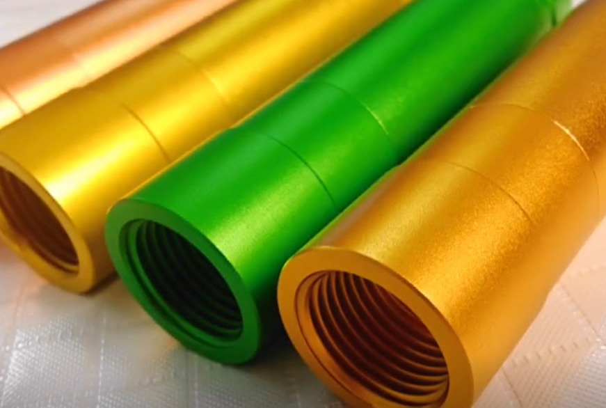
- Anodizing of aluminum housings for corrosion protection and electrical insulation
- Electroless nickel or nickel‑phosphorus coatings for wear resistance and barrier layers
- Passivation of stainless steels to enhance corrosion resistance
- Hard coatings such as TiN or DLC on wear surfaces in mechanical sensor components
Coating processes require coordination with machining, as dimensions may need to account for coating thickness, and masking may be necessary in sealing or electrical contact regions.
Cleaning and Contamination Control
Cleanliness is essential in many sensor applications, especially in medical, pharmaceutical, vacuum and clean gas measurement. Post‑machining cleaning removes cutting fluids, chips, abrasives, and other residues. Methods can include:
- Aqueous cleaning with detergents and ultrasonic agitation
- Solvent‑based cleaning in closed systems
- Specific degreasing and drying procedures for oxygen service components
Cleanliness levels may be specified in particle counts, residual film thickness, or visual inspection criteria. Parts may be packed in controlled environments to maintain cleanliness until final assembly.
Cost Structure in Sensor Machining
The cost of machined sensor components results from a combination of material cost, machine time, tooling, labor, overhead and quality assurance. Understanding the main cost drivers helps in design and sourcing decisions.
| Cost Driver | Influence on Cost | Typical Considerations |
|---|---|---|
| Material type | Medium to high | Stainless steel and titanium are more expensive than aluminum or brass; ceramics and special alloys significantly increase raw material and processing cost. |
| Part complexity | High | More surfaces, setups and features increase machining time and fixturing complexity. |
| Tolerances and surface finish | High | Tight tolerances and very smooth surfaces require slower cutting, additional operations (e.g., grinding), and extensive inspection. |
| Batch size | High | Small batches incur more setup cost per piece; large batches amortize setup and tooling over more parts. |
| Tooling and fixturing | Medium | Custom fixtures and specialized tools increase initial investment but can reduce unit cost at volume. |
| Secondary operations | Medium to high | Deburring, coatings, heat treatment and cleaning add processing steps and logistics. |
| Quality assurance | Medium | Complex measurement requirements and documentation increase inspection time and equipment needs. |
Cost Impact of Materials and Part Geometry
Materials influence both raw cost and machining effort. For example, stainless steels and titanium have higher purchase prices and lower machining speeds compared to aluminum. Complex geometries with deep cavities, thin walls or micro‑features require more toolpaths, slower feeds and careful fixturing, which increases machining time and setup requirements.
Where possible, designs that allow uniform wall thicknesses, accessible features and reduced number of setups help control cost without compromising performance.
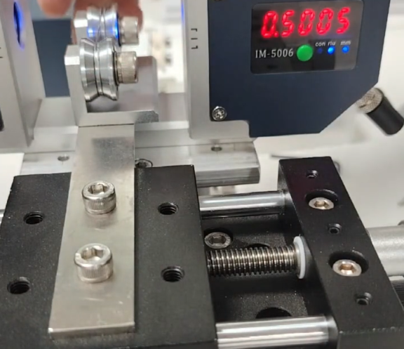
Tolerances, Surface Requirements and Inspection Effort
Tight tolerances and high finish requirements not only lengthen machining cycles but also increase the need for detailed measurement and documentation. Cost increases arise from:
- Additional process steps such as grinding or lapping
- Reduced cutting speeds to maintain accuracy
- Use of precision measurement equipment like coordinate measuring machines (CMMs)
- Increased frequency of in‑process and final inspection
Therefore, tolerances should be function‑driven. Each dimension should be evaluated for its impact on sensor performance, and only those that directly affect function should be tightly controlled.
Batch Size and Setup Cost Allocation
Setup cost includes programming, fixture installation, first‑article inspection and machine calibration. This cost is largely fixed per batch and is divided over the number of parts produced. Small batch sizes result in higher unit costs because setup overhead is spread over fewer pieces.
For ongoing sensor production, grouping orders into larger batches or designing families of parts that share common features and fixtures can reduce the unit cost by minimizing setup frequencies and exploiting economies of scale.
Tooling, Fixturing and Automation Effects on Cost
Dedicated fixtures and tooling reduce cycle time and improve repeatability but require initial investment. For medium and high volumes, this investment is usually offset by lower unit cost through faster machining, reduced manual handling and fewer quality issues.
Automation, such as automatic loading or integrated deburring, adds equipment cost but can reduce labor and increase machine utilization, especially in multi‑shift or high‑volume environments.
Design Considerations for Machinable Sensor Parts
Design decisions critically influence machinability and thus cost, lead time and quality. Coordination between design engineers and manufacturing engineers is essential to create sensor components that meet functional requirements while being economical to produce.
Feature Design for Efficient Machining
To facilitate machining:
- Avoid unnecessary undercuts or features that require special tools or multiple setups.
- Provide adequate tool access and clearance for cutters and drills.
- Standardize hole sizes and thread types across a sensor family where possible.
- Limit extremely thin walls or deep, narrow pockets unless functionally necessary.
- Use consistent datum schemes that match fixturing concepts.
Design for manufacturability shortens development cycles and improves the feasibility of scaling from prototypes to series production.
Wall Thickness, Threads and Sealing Features
Wall thickness should balance mechanical strength and machinability. Very thin walls may vibrate during cutting, leading to poor surface finish and dimensional variation. In pressure sensors, minimal wall thickness is constrained by pressure rating and material strength, often calculated based on standard pressure vessel formulas.
Thread design must align with the intended application and applicable standards. For process connections, common thread standards include NPT, BSPP, BSPT and metric threads. Correct tolerances on pitch diameter, concentricity and perpendicularity are important for leak‑free connections.
Sealing features such as O‑ring grooves must follow appropriate standards for groove width, depth and corner radii. Surface finish in these areas is critical; roughness and dimensional deviations can cause leaks and premature seal wear.
Mounting Interfaces and Integration into Systems
Sensors often need precise and robust attachment to equipment, pipes, vessels or mechanical structures. Mounting features include:
- Flanges with bolt patterns
- Clamping grooves for clamp‑on sensors
- Threaded bosses or studs
- Alignment features such as dowel holes and keyways
These interfaces must be designed for ease of assembly, adequate stiffness and correct orientation of the sensing element. Machining quality in these areas directly affects installation repeatability and measurement consistency.
Practical Issues in Sensor Machining
While sensor machining uses established processes, several recurring issues must be addressed to ensure reliable production and stable performance.
Thin‑Wall Distortion and Dimensional Instability
Thin housings, diaphragms and small features may distort during machining or subsequent operations. Contributing factors include residual stresses from material production, clamping forces and heat input during cutting. Distortion can lead to misalignment, sealing problems and zero‑point shifts in pressure sensors.
Mitigation measures include careful selection of stock material, stress‑relief treatments, optimized clamping and machining strategies that balance material removal and minimize localized heating.
Burrs, Particles and Their Effect on Sensor Performance
Burrs and machining residues can obstruct small channels, damage sealing surfaces or create contamination in sensitive measurement environments. In flow and pressure sensors, tiny particles may block or partially obstruct pressure ports and flow passages, causing offset or drift in measurement output.
Effective deburring and cleaning processes are therefore essential, particularly for small orifices and internal passages that are difficult to access manually.
Consistency Across Batches and Long‑Term Stability
Sensors are often calibrated to high accuracy and expected to remain stable over long periods. Variation in machined dimensions between batches can impact assembly conditions, preloads, diaphragm deformation and internal clearances, leading to calibration shifts or drift.
Stable machining processes with controlled tools, fixtures, and inspection regimes help keep critical dimensions within tight, consistent limits over time.
FAQ About Sensor Machining
What machining tolerances are typically required for industrial pressure sensor housings?
Typical tolerances for industrial pressure sensor housings depend on the specific features. General external dimensions often use ±0.05–0.1 mm. Critical bores for sensor elements or diaphragms are normally in the range of ±0.01–0.02 mm. Mounting faces and sealing surfaces may require flatness around 0.02–0.05 mm and surface roughness Ra 0.4–1.6 μm. More demanding applications, such as high‑precision transmitters, may specify tighter tolerances on selected features, but these are limited to dimensions that directly affect sensor calibration and sealing.
Which materials are most commonly machined for sensor housings?
The most commonly machined materials for sensor housings are stainless steels such as 304, 316/316L and 17‑4PH due to their corrosion resistance and mechanical strength. Aluminum alloys like 6061‑T6 are also widely used for lighter housings and electronics carriers. Brass or other copper alloys are chosen for fittings and specific low‑pressure components. For demanding environments, titanium alloys may be used. Engineering plastics such as PEEK, PTFE and POM serve as insulating or chemically resistant parts, but metals remain predominant for main housings and process connections.
How does batch size affect the unit cost of machined sensor parts?
Batch size has a direct effect on unit cost because setup work such as programming, fixturing and first‑article inspection is largely independent of the number of parts produced. In small batches, the fixed setup cost is distributed across few parts, resulting in higher unit cost. Larger batches spread this overhead, reducing cost per piece. At higher volumes, additional savings come from optimized tooling, dedicated fixtures and potential automation. For recurring sensor parts, designing for commonality and grouping orders into larger production runs is an effective way to reduce unit cost.
Why are post‑machining cleaning processes important for sensor components?
Post‑machining cleaning processes remove cutting fluids, chips, abrasives and other contaminants that can interfere with sensor operation. In pressure and flow sensors, small particles can block channels or ports. In medical and pharmaceutical sensors, residual contamination can compromise sterility and product safety. In electrical and optical sensors, films of oil or particulates may degrade signal quality. Proper cleaning, often using aqueous or solvent systems with ultrasonic agitation, helps ensure reliable operation, stable calibration and compliance with application‑specific cleanliness standards.
When is grinding necessary in sensor machining instead of only turning and milling?
Grinding is used when required tolerances and surface finishes cannot be achieved economically by turning and milling alone. It is typical for sealing surfaces in high‑pressure sensors, flat reference faces in displacement or optical sensors, and hardened components that would cause rapid wear to cutting tools. Grinding provides tight dimensional control (often within ±0.002–0.005 mm) and fine surface finishes (Ra around 0.1–0.4 μm). It is applied selectively to critical areas to balance precision requirements with production cost.
