
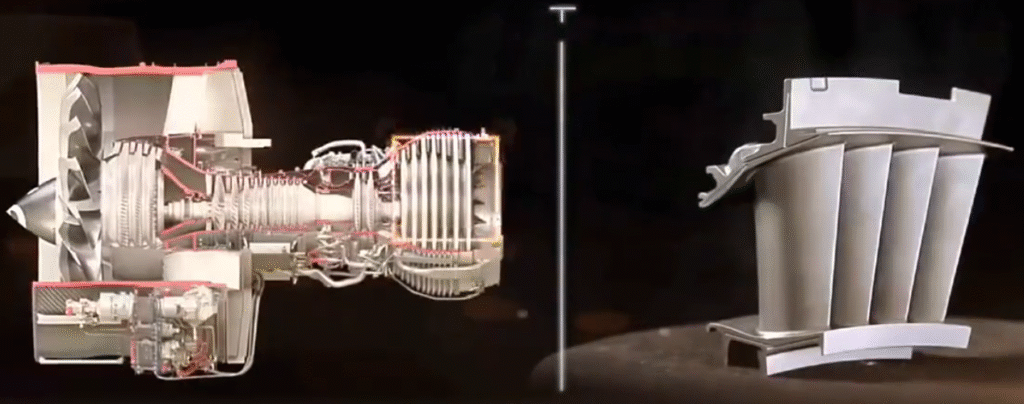
Turbine blades are critical rotating components in gas, steam and aero engines, directly affecting efficiency, reliability and safety. Their complex 3D geometry, tight tolerances, demanding materials and harsh operating environment require a controlled, traceable and highly repeatable machining and inspection strategy.
Overview of Turbine Blade Types and Materials
Turbine blades vary significantly depending on application, stage and operating conditions, but they share common geometrical and material characteristics that drive machining and inspection requirements.
Main Types of Turbine Blades
Turbine blades are generally classified by application and function:
- Gas turbine blades (industrial and aero engines)
- Steam turbine blades (low-pressure and high-pressure stages)
- Guide vanes / nozzle guide vanes (stationary, but similar to blades in geometry)
Within each machine type, blades differ by stage position:
Gas turbine blades typically include:
- High-pressure turbine (HPT) blades: usually single-crystal or directionally solidified nickel-based superalloys, often with internal cooling passages and thermal barrier coatings.
- Intermediate/low-pressure turbine blades: less extreme temperatures, often polycrystalline superalloys or advanced steels.
Steam turbine blades typically include:
- High-pressure and intermediate-pressure blades: martensitic stainless steels, CrMoV alloys.
- Low-pressure last-stage blades: large, long blades with complex damping and root systems, usually martensitic stainless steels.
Typical Blade Geometry Features Impacting Machining
Important geometric elements that directly influence machining strategy and tolerance setting include:
- Airfoil: pressure and suction surfaces, leading edge, trailing edge, and platform fillets.
- Root: fir-tree, dovetail, or other serrated forms that fit into the turbine disk or rotor.
- Platform or shroud: radial or circumferential features controlling gas path and sealing.
- Tip: may include shrouds, squealer tips, seal fins or wear pads, with tight clearance to the casing.
Each of these surfaces has distinct tolerance, surface integrity and inspection requirements.
Common Materials for Turbine Blades
Turbine blades are manufactured from materials with high temperature capability, creep resistance and corrosion resistance. Common categories include:
For gas turbines:
- Nickel-based superalloys (single crystal, directionally solidified, equiaxed).
- Cobalt-based superalloys for specialized hot-section applications.
For steam turbines:
- Martensitic stainless steels (e.g., 12% Cr steels).
- CrMoV and other low-alloy steels for high-pressure and intermediate-pressure stages.
These materials are generally difficult to machine due to high strength at elevated temperatures, work hardening, poor thermal conductivity and abrasive precipitates.
Manufacturing Route and Machining Position in the Process Chain
Turbine blades are not produced by machining alone. Machining is one stage within a longer process chain designed to achieve structural integrity, dimensional conformity and surface quality.
Typical Manufacturing Process Chain
| Process Stage | Main Purpose | Typical Operations |
|---|---|---|
| Primary shaping | Produce near-net-shape blank | Investment casting, precision forging, machining from solid |
| Heat treatment | Achieve required microstructure and mechanical properties | Solution treatment, aging, stress relief |
| Chemical processing | Clean and refine surfaces, open cooling channels | Descaling, leaching, chemical milling |
| Rough machining | Datum creation and stock removal | Turning of root region, milling reference faces |
| Semi-finish machining | Approach final geometry, control distortion | 3-axis/5-axis milling of airfoil and root, drilling |
| Finish machining | Achieve final dimensions and surface finish | Finish milling, grinding, honing, EDM for features |
| Coating | Provide environmental and thermal protection | Bond coat, ceramic thermal barrier coating, aluminizing |
| Post-coating machining | Restore critical fits and clearances | Tip grinding, platform surface correction, hole clearing |
| Final inspection | Verify conformity and release to service | CMM, optical scanning, NDT, balance measurement |
Machining steps occur at multiple points, with tolerance allocation and inspection planned across the entire chain rather than at a single stage.
Machining Objectives in the Process Chain
The machining strategy for turbine blades typically aims to:
- Establish datums that are stable and compatible with subsequent operations.
- Control stock removal to maintain structural integrity and minimize distortion.
- Achieve target surface integrity (residual stress state, microhardness, absence of microcracks).
- Meet geometric tolerances for form, profile, runout and alignment.
- Provide reliable measurement references for in-process and final inspection.
Fixturing, Datums and Workholding for Turbine Blades
Stable, repeatable fixturing is essential due to slender geometries, non-uniform cross-sections and thin airfoil sections. Poor fixturing can lead to dimensional errors, chatter, distortion and inconsistent inspection results.
Datum Strategy
Typical datum choices include:
- Root faces and serrations: primary datums for rotational positioning and radial reference.
- Platform surfaces: secondary datums for gas path alignment.
- Temporary machined pads or holes: auxiliary datums for specific local operations, later removed.
Datums should be compatible between manufacturing and inspection to avoid coordinate system transformation errors and complexity in data evaluation.
Workholding Concepts
Common workholding solutions include:
- Mechanical root clamping: clamping on fir-tree or dovetail root profiles using matched form fixtures.
- Platform clamping: suitable for robust platforms, often in combination with tailstock or support pins near the tip.
- Soft jaws and custom nests: shaped to support the airfoil while minimizing over-constraining.
- Vacuum fixtures: used selectively for large, thin surfaces where clamping forces must be minimized.
Workholding designs must balance stiffness, accessibility for cutting tools and inspection probes, and protection of critical surfaces from damage.
CNC Machining Processes for Turbine Blades
The majority of turbine blade machining is performed on CNC machines, with operations selected according to geometric requirements, material and productivity targets.
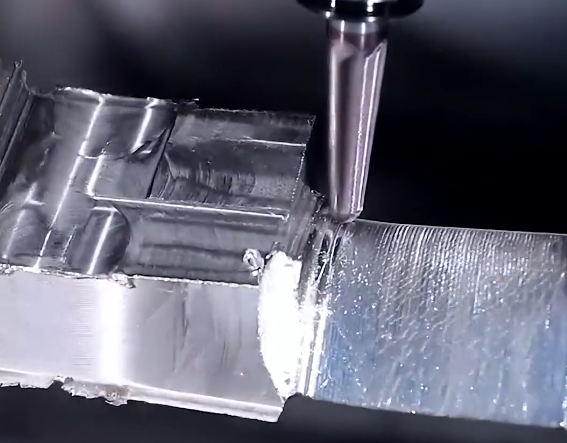
Rough Machining
Rough machining removes excess stock from cast or forged blanks, establishes datums and creates a consistent geometry for semi-finishing. Typical operations include:
- Root roughing: 3-axis or 4-axis milling of the fir-tree or dovetail region.
- Airfoil roughing: 5-axis milling using ball nose or barrel tools, leaving a defined allowance for semi-finishing.
- Platform and shroud roughing: face milling, contour milling and slotting.
Typical considerations:
- Stock allowance: commonly 0.3–1.5 mm per side depending on process route, casting quality and thermal distortion risk.
- Cutting parameters: moderate cutting speed and feed to avoid excessive heat and work hardening in superalloys.
- Coolant: high-pressure coolant to remove chips and control temperature.
Semi-Finish Machining
Semi-finish operations refine the geometry and bring critical features closer to size while leaving a smaller, uniform stock for finishing. Objectives include:
- Minimize variation in remaining stock to ensure stable finishing.
- Reduce distortion caused by uneven stresses from heavy roughing cuts.
Practical parameters:
- Typical remaining stock: 0.1–0.4 mm per side for airfoil surfaces, depending on material and finishing method.
- Feed and step-over: adjusted to maintain stable cutting forces and acceptable surface quality for reliable in-process measurement.
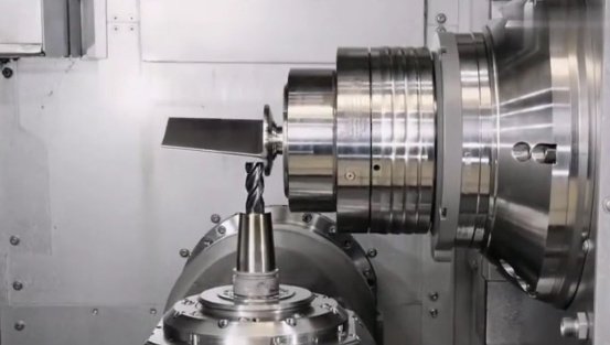
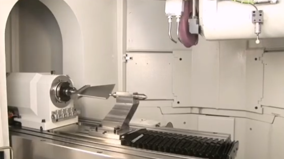
Finish Machining of Airfoil Surfaces
Airfoil surfaces require high accuracy in profile, twist, lean and throat area, with controlled surface finish. Finish machining is often performed on 5-axis machining centers or dedicated blade milling machines.
Key aspects:
- Tooling: ball nose end mills, barrel cutters, lens cutters and form tools, selected according to curvature and finish requirements.
- Stepover and scallop height: typically controlled to obtain surface roughness in the Ra 0.4–1.6 µm range, depending on application.
- Toolpath strategy: continuous 5-axis machining with consistent engagement to reduce marks and transitions between passes.
Special consideration is required for leading and trailing edges, which may need smaller tools, reduced feeds and specific path strategies to avoid gouging and maintain edge thickness within tolerance.
Root Machining
Root geometry (fir-tree or dovetail) controls blade retention and load transfer into the disk or rotor. It usually demands tight dimensional and form tolerances, and a favorable surface integrity to resist fretting and fatigue.
Typical root machining practices:
- Precision milling with form cutters or multilayer finishing passes to achieve flank and fillet form.
- Grinding of root flanks for high-precision applications, achieving tighter tolerances and better surface finish.
- Control of edge radius and fillet shape, which influences stress distribution and life.
Surface finish for root contact surfaces is often specified in the range of Ra 0.2–0.8 µm, depending on the design criteria and anti-fretting requirements.
Shroud, Platform and Tip Machining
Shroud and platform surfaces contribute to sealing, vibration characteristics and gas path control. Tip machining controls clearance to the casing or seal segments.
Common operations include:
- Platform milling: controlling height and planarity relative to root datums.
- Shroud contouring: machining interlocking features and sealing surfaces.
- Tip grinding: establishing final tip height and profile, especially after coating.
Tip clearance requirements may demand dimensional tolerances of ±0.03–0.10 mm or tighter, depending on engine design and stage position.
Holes, Slots and Cooling Features
Hot-section blades, especially in gas turbines, often incorporate complex cooling systems. Machining operations for these features may include:
- Drilling of cooling holes: mechanical drilling, electro-discharge machining (EDM) or laser drilling.
- Slotting and diffusers: using EDM or 5-axis milling.
- Film cooling holes: often with tight positional and angle tolerances to ensure correct coolant flow and film coverage.
Hole diameters can range from approximately 0.3 mm to several millimeters, with angle tolerances on the order of ±1–3 degrees relative to design direction.
Cutting Parameters and Tooling Considerations
Tool and parameter selection for turbine blade machining is heavily influenced by material and geometry. Detailed cutting data are usually based on tool supplier recommendations and internal process development, but general trends can be described.
Tools for Superalloy Gas Turbine Blades
For nickel-based superalloys, tool solutions often include:
- Solid carbide end mills with high-temperature coatings (e.g., TiAlN, AlTiN) for roughing and semi-finishing.
- Carbide or cermet inserts for roughing operations where accessibility permits.
- PCBN or ceramic tools for specific high-efficiency roughing operations, usually with controlled engagement and high-speed cutting.
Typical ranges of cutting parameters (which must be validated in each application) can include:
- Cutting speed: approximately 20–80 m/min for carbide in nickel superalloys, depending on tool type and operation.
- Feed per tooth: generally around 0.03–0.15 mm/tooth for finishing with small-diameter tools, higher for roughing with larger tools.
Tools for Steam Turbine Blade Steels
Martensitic stainless steels and CrMoV steels allow higher cutting speeds than nickel superalloys, but attention to work hardening and chip breaking is still required.
- Carbide tools with TiCN, TiAlN or similar coatings are common.
- Cutting speeds can range more widely, e.g. 80–200 m/min, subject to stability and life requirements.
Coolant and Chip Evacuation
High-pressure coolant is frequently used to:
- Control cutting zone temperature and prevent thermal damage.
- Improve chip evacuation in deep cuts and complex geometries.
- Extend tool life and stabilize cutting forces.
Coolant supply must be designed to avoid impingement on sensitive surfaces at high velocity and to prevent re-cutting of chips.
Dimensional and Geometrical Tolerances for Turbine Blades
Tolerances for turbine blades are typically defined in detailed engineering drawings or digital product definition structures. They address dimensions, form, orientation, position and surface properties.
Airfoil Profile and Form Tolerances
Airfoil geometry is usually specified by reference to a nominal CAD model with associated profile tolerance zones. Common requirements include:
- Profile of a surface: frequently in the range of 0.03–0.20 mm, depending on design and position in the machine.
- Camber and thickness: local cross-sections with thickness tolerances often around ±0.05–0.10 mm.
- Twist and lean: controlled via reference sections, requiring angular control typically within ±0.1–0.3 degrees.
Throat area and flow area between blades in a row is also critical. Tolerance on throat area may be derived from aerodynamic requirements and often leads to tight control of adjacent profile segments.
Root and Platform Tolerances
Root geometry directly affects fitting into the disk and load transfer; tolerances therefore are relatively tight.
- Key dimensions such as flank heights, widths and angles may be held within ±0.01–0.03 mm.
- Form tolerances for flank straightness and fillet shape are often specified to ensure uniform stress distribution.
- Platform flatness and parallelism to root datums often lie in the range 0.01–0.05 mm.
Tip and Shroud Tolerances
Tip clearances have a strong influence on stage efficiency. Typical requirements can involve:
- Tip height tolerance of ±0.03–0.10 mm relative to root or platform datums.
- Shroud radial and axial positions controlled to similar levels.
- Runout of tip relative to the blade rotation axis controlled to ensure uniform clearance.
Surface Roughness Requirements
Surface roughness is specified according to function:
- Airfoil surfaces: often Ra 0.4–1.6 µm, sometimes with additional parameters (Rz, waviness) for aerodynamic performance.
- Root contact surfaces: Ra typically 0.2–0.8 µm to reduce fretting and ensure stable load transfer.
- Shroud and tip seal surfaces: roughness chosen to balance sealing performance and wear characteristics.
In-Process Control and Compensation
Because turbine blades are slender and sensitive to thermal and mechanical influences, in-process control is used to maintain tolerances and reduce scrap.
In-Process Dimensional Checks
Typical checks performed during machining include:
- Datums verification: probing of root faces and machined pads to confirm alignment.
- Critical section measurements: thickness and chord at defined airfoil sections.
- Tip and platform heights: to ensure adequate stock remains for final finishing and to avoid undercutting.
On-machine probing systems are frequently used to measure reference points or sections, and to generate offsets for subsequent toolpaths.
Tool Wear Monitoring and Compensation
Tool wear directly influences surface finish, profile accuracy and edge integrity. Monitoring approaches may include:
- Preset tool life limits based on empirical data.
- Monitoring spindle load or vibration patterns to identify abnormal wear.
- In-process measurement of sample features to adjust tool wear compensation values.
Compensation is commonly carried out via tool length/radius offsets and, for complex profiles, by adjusting toolpath data in the CNC program.
Final Inspection of Turbine Blades
Final inspection verifies that each blade conforms to specification and is suitable for assembly and service. It includes dimensional metrology, surface and structural integrity checks, and functional tests where applicable.
Coordinate Measuring Machine (CMM) Inspection
Contact CMM inspection is widely used for high-accuracy dimensional verification.
Key elements of CMM inspection:
- Establishing the same datum structure as in machining and design to minimize alignment errors.
- Measuring a dense set of points or sections on the airfoil, root and platform.
- Comparing measured geometry against CAD models or nominal curves and surfaces.
Airfoil inspection often uses defined cross-sections at specific heights above the platform. At each section, multiple parameters are extracted, such as leading and trailing edge positions, thickness, chord length and profile deviation relative to nominal.
Non-Contact Optical and Laser Scanning
Non-contact scanning technologies are used when speed and dense surface coverage are needed, and to avoid contact forces on thin sections.
Common technologies include:
- Structured light scanners.
- Laser line scanners on CMMs or dedicated scanning systems.
- High-resolution camera-based systems with photogrammetric alignment.
Measured point clouds are aligned to the nominal CAD model, and deviations are analyzed using color maps and numerical statistics. This allows quick identification of local profile variations, edge conditions and surface waviness.
Surface Roughness and Topography Measurement
Surface finish is commonly checked using stylus profilometers or optical profilometers.
Typical inspection steps:
- Select measurement traces or areas on representative regions (pressure side, suction side, leading edge, root flanks).
- Measure Ra and other parameters according to the specified standard.
- Compare with tolerance bands and assess consistency across the blade population.
Non-Destructive Testing (NDT)
To ensure structural integrity, several NDT methods are applied, usually after machining and sometimes repeated after coating or heat treatment.
Common NDT methods for turbine blades include:
- Fluorescent penetrant inspection: to detect surface-breaking cracks on airfoil, root and platform.
- Radiographic inspection: to check internal defects in cast or welded regions.
- Ultrasonic inspection: to detect internal flaws and verify bonding in certain designs.
NDT complements dimensional inspection by ensuring that machining has not introduced cracks, burns or residual damage that could lead to in-service failure.
Balance and Mass Properties
For rotating assemblies, blade mass and moment properties must lie within defined limits to control vibration and dynamic loads.
Common checks include:
- Blade mass measurement with tolerances commonly in the range of ±0.5–2 g, depending on size and stage.
- Center of gravity location relative to root datums.
- Moment weight or pair matching within a set of blades for balanced assembly.
Where required, small balance corrections can be applied by controlled material removal at pre-defined locations, followed by re-measurement.
Data Management and Traceability
Reliable turbine blade manufacturing requires systematic management of process and inspection data. Dimensional results, process settings and material data must be traceable to individual blades, batches and machines.
Typical data elements recorded per blade may include:
- Material batch and heat treatment history.
- Machine ID, program revision and key cutting parameters used.
- Inspection results for critical dimensions, airfoil profile, root geometry and surface finish.
- NDT results and any rework or repair actions.
Data traceability supports process capability analysis, identification of systematic deviations and long-term quality assurance for safety-critical components.
Common Practical Issues in Turbine Blade Machining
Despite advanced machinery and tooling, turbine blade machining presents recurring practical issues that must be controlled through process design and monitoring.
Workpiece Distortion
Thin airfoil sections and residual stresses from casting or heat treatment can cause distortion during or after machining. Uneven stock removal tends to release stresses, leading to twist, bow or local bending.
Mitigation strategies include:
- Balancing material removal between pressure and suction sides.
- Intermediate stress-relief operations when specified by design or process development.
- Sequencing operations to minimize asymmetrical loading and clamping forces.
Surface Integrity and Microcracks
Excessive heat, tool wear or inappropriate cutting parameters can create microcracks, white etching layers and unfavorable residual stresses, particularly in superalloys.
Controls include:
- Defined limits for cutting speeds, feeds and depth of cut.
- Mandatory tool changes or inspections after a specified cutting time or length.
- Surface integrity checks (etching, metallographic inspection) during process qualification.
Edge Quality at Leading and Trailing Edges
Leading and trailing edges are thin and delicate, with tight thickness and radius requirements. Issues include burr formation, chipping and local over- or under-size conditions.
Common measures:
- Dedicated finishing strategies with small tools and controlled engagement.
- Fine hand deburring within defined limits when permitted, combined with consistent documentation.
- Focused inspection of edge thickness and radius at multiple sections.
Measurement Consistency Between Sites and Systems
Turbine blade production may involve multiple plants or suppliers. Differences in fixturing, CMM programming, filtering and alignment methods can lead to inconsistent measurement results.
To reduce discrepancies, organizations typically:
- Standardize datum definitions and measurement strategies.
- Use common CAD datasets and inspection templates.
- Perform correlation studies between CMMs and optical systems.
FAQ: Turbine Blade Machining, Tolerance and Inspection
What is turbine blade machining?
Turbine blade machining is the process of shaping turbine blades using precision techniques such as CNC milling, grinding, electrical discharge machining (EDM), and polishing to meet strict design and aerodynamic requirements.
How is tolerance measured in turbine blades?
Tolerance is measured using precision metrology tools like CMMs, laser scanners, and profilometers, which can accurately check 3D geometry, blade angles, and surface contours.
What challenges are common in turbine blade machining?
Challenges include maintaining tight tolerances on complex 3D curves, minimizing vibration and tool deflection, avoiding material deformation, and achieving consistent surface finish.
How can turbine blade quality be ensured throughout production?
Quality is ensured by strict process control, skilled CNC programming, in-process inspections, post-machining measurement, and proper finishing techniques, ensuring each blade meets design specifications.
