

Material selection is a critical decision in prototype development. Choosing between rigid and flexible prototyping materials affects performance, manufacturability, cost, and the quality of test data you obtain. This guide explains how each category behaves, which processes and materials are commonly used, and how to match material choice to the functional requirements of your prototype.
Fundamentals of Rigid and Flexible Prototyping
Rigid and flexible prototypes differ primarily in how they respond to load, deformation, and repeated use. Understanding these differences at a basic mechanical level helps you choose the correct approach early in a project.
Rigid Prototypes: Definition and Core Characteristics
Rigid prototypes are made from materials that exhibit high stiffness, low elastic deformation under operational loads, and stable geometry. They are usually intended to maintain shape and dimensions even under moderate mechanical or thermal stresses.
Typical mechanical characteristics for rigid prototype materials (approximate ranges for design comparison):
- Tensile modulus: ~1,500–210,000 MPa (from rigid plastics to metals)
- Tensile strength: ~35–1,200 MPa
- Elongation at break: typically < 20% for many engineering plastics and metals used for rigid parts
Rigid prototypes are commonly used for structural components, housings, mounts, brackets, enclosures, and any element where geometric stability, load-bearing capability, and dimensional accuracy are priorities.
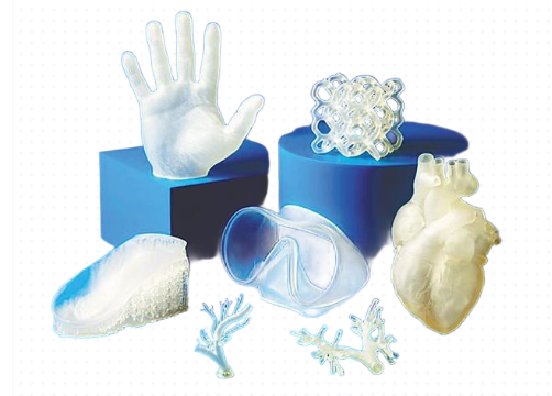
Flexible Prototypes: Definition and Core Characteristics
Flexible prototypes are made from materials that allow significant elastic or viscoelastic deformation without permanent damage. They are selected when bending, stretching, compressing, or twisting is part of the normal operation of the part.
Typical mechanical characteristics for flexible prototype materials (again, broad ranges):
- Tensile modulus: ~1–80 MPa for elastomers and soft flexible polymers
- Tensile strength: ~2–50 MPa
- Elongation at break: often 200–700% or higher, depending on elastomer formulation
Flexible prototypes are prevalent for seals, gaskets, wearable straps, soft-touch interfaces, living hinges, cable boots, bellows, and flexible electronic substrates. They are also used for ergonomic and human-interaction testing where compliance and comfort are important.
Key Material Properties for Rigid vs Flexible Prototypes
To choose between rigid and flexible materials, it is helpful to compare the most relevant material properties for prototyping applications.
| Property | Rigid Materials (Typical) | Flexible Materials (Typical) |
|---|---|---|
| Tensile Modulus (Young’s Modulus) | Rigid plastics: ~1,500–3,500 MPa; Aluminum: ~69,000 MPa; Steel: ~200,000 MPa | Elastomers: ~1–20 MPa; Flexible TPUs: ~20–80 MPa |
| Tensile Strength | Rigid plastics: ~40–80 MPa; Aluminum alloys: ~150–400 MPa; Steel: ~400–1,200 MPa | Elastomers and flexible TPUs: ~2–50 MPa |
| Elongation at Break | Rigid plastics: often 2–10%; Metals: 5–30% depending on alloy | Elastomers: 200–700% or higher |
| Hardness (Shore) | Rigid plastics: Shore D 70–85; Metals: beyond Shore D scale, treated as very hard | Soft elastomers: Shore A 10–40; General elastomers: Shore A 40–90; Some flexible blends: Shore D 20–50 |
| Service Temperature (Approx.) | Standard rigid plastics: ~-40 to 80–110°C; High-temp plastics and metals tolerate significantly higher temperatures | Elastomers: ~-50 to 80–120°C depending on chemistry; performance may change substantially near limits |
| Dimensional Stability | High; low deformation under load when properly designed | Lower; shape depends strongly on load, thickness, and support conditions |
| Fatigue Behavior | Good for metals and some engineering plastics; sensitive to stress concentrations | Can be excellent for elastic deformation, but sensitive to cuts, notches, and environmental aging |
| Typical Use Case in Prototyping | Enclosures, frames, brackets, structural parts, precision assemblies | Seals, hinges, gaskets, wearable components, soft-touch and impact-absorbing elements |
When selecting between rigid and flexible prototypes, designers evaluate these parameters against the functional requirements and expected loading of the part. Matching mechanical behavior to real-world use is more important than copying the exact production material at early stages, as long as the prototype provides representative performance data.
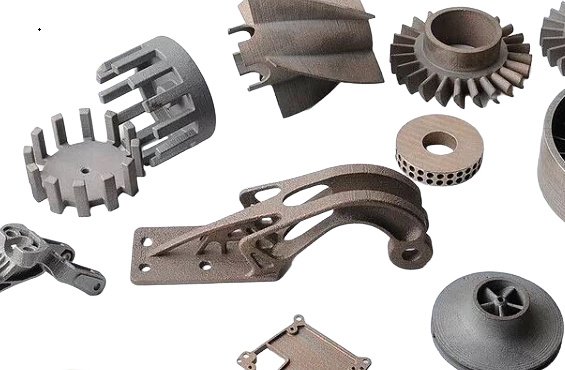
Common Rigid Prototyping Processes and Materials
Rigid prototypes can be produced using additive manufacturing, subtractive machining, and molding or casting. Each method has typical materials, tolerances, and use cases.
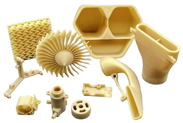
Additive Manufacturing for Rigid Prototypes
Additive processes are widely used for rigid prototypes thanks to fast turnaround and low tooling cost. Key technologies include Fused Deposition Modeling (FDM), Stereolithography (SLA), and Selective Laser Sintering (SLS), along with other powder bed fusion and jetting methods.
Common rigid materials used in 3D printing:
- FDM thermoplastics: PLA, ABS, PETG, PA (nylon), PC, and filled blends
- SLA photopolymers: Standard rigid resins, high-temperature resins, toughened resins
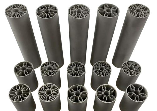
- SLS powders: Nylon 12, Nylon 11, glass-filled or mineral-filled nylon
Typical performance aspects:
FDM rigid plastics: Dimensionally stable for conceptual and functional testing, with layer-dependent surface quality and anisotropic mechanical behavior. Layer heights commonly range from 0.1–0.3 mm, with achievable dimensional tolerances in the range of ±0.2–0.5 mm depending on machine, material, and build size.
SLA rigid resins: Suitable when high detail and smooth surfaces are needed. They provide fine features, thin walls, and small internal channels. Typical minimum feature size can be ~0.1–0.3 mm, with dimensional tolerances on the order of ±0.1–0.2 mm. Photopolymers may be more brittle than production thermoplastics and are sensitive to UV and environmental exposure.
SLS nylon: Offers good balance of strength, stiffness, and toughness. No support structures are required because the powder bed provides support, making it suitable for complex geometries and nested parts. Tolerances are typically around ±0.3% (with a lower bound in the range of ±0.3 mm for small dimensions).
CNC Machining for Rigid Prototypes
CNC machining uses subtractive manufacturing to produce rigid prototypes directly from solid stock. It is commonly used for metal and engineering plastic parts that must closely approximate end-use performance.
Typical materials:
- Metals: Aluminum 6061, 7075; Stainless steels (304, 316); Carbon steels; Brass
- Rigid plastics: ABS, POM (acetal), PEEK, PC, PA, PTFE, and various engineering grades
Machined prototypes can achieve tight tolerances, often down to ±0.05 mm or tighter on well-controlled features. Surface finishes can be tailored using milling parameters and post-processing such as bead blasting or polishing. Metal prototypes are particularly useful for mechanical testing, thermal management evaluation, and validation of assembly interfaces that need high stiffness and precise dimensions.
Molding and Casting for Rigid Prototypes
For slightly higher volumes or when material behavior must be close to production-grade plastics, molding and casting techniques are used.
Common approaches:
Urethane casting in silicone molds: Rigid polyurethane systems can simulate many thermoplastic properties. Shrinkage and dimensional tolerances depend on formulation and mold design but can be controlled to the range of ±0.1–0.3 mm for small parts. These prototypes suit functional testing, fit checks, and short pilot runs.
Low-volume injection molding: Aluminum or soft steel tooling is used to mold engineering plastics in small to medium runs. This method delivers prototypes with near-production material properties and surface finishes, suitable for final validation of mechanical performance, assembly, and user interaction. Tooling cost is higher than 3D printing or casting but lower than full hardened steel production tools.
Common Flexible Prototyping Processes and Materials
Flexible prototypes require materials and processes that maintain elasticity and durability under repeated deformation. Key approaches include flexible 3D printing, casting elastomers, and molding flexible thermoplastics.
Additive Manufacturing for Flexible Prototypes
Additive methods have expanded the range of flexible materials available for rapid prototyping. While properties might not match production elastomers exactly, many applications can be approximated sufficiently for testing.
Typical processes and materials:
- FDM with flexible filaments: TPU (thermoplastic polyurethane), TPE (thermoplastic elastomer)
- SLA with flexible resins: Rubber-like or elastomeric photopolymers
- Material jetting: Multi-material jets that simulate rubber-like behavior
Key characteristics:
FDM flexible filaments: Shore hardness typically from A 85 to 98 for common TPUs, with elongation at break in the range of 200–600%. Flexibility depends on shore hardness, wall thickness, infill pattern, and print orientation. Printing can be slower due to filament softness, and dimensional accuracy may be in the range of ±0.3–0.6 mm, depending on the machine and geometry.
Flexible SLA resins: Offer smooth surfaces and fine details with hardness values often in the Shore A 50–80 range. They are suitable for seals, overmolds, and soft-touch features in early design stages. Certain photopolymers may show long-term creep or changes in stiffness over time, especially under constant load or UV exposure.
Material jetting: Some systems can jet multiple materials to build parts with gradient stiffness or combined soft and hard regions. This is useful for simulating overmolded grips, living hinges, and integrated seals. Layer resolutions as low as 16–30 microns are possible, with fine feature reproduction. Mechanical properties depend on proprietary material blends but often resemble rubber-like plastics more than true industrial elastomers.
Elastomer Casting for Flexible Prototypes
Cast elastomers are widely used when flexible parts must more closely mimic production rubber components. Casting requires a mold, which can be machined or 3D printed, enabling complex geometries.
Common elastomer systems:
- Silicone rubber: Wide range of Shore A hardness from very soft (~10A) to firm (~70A)
- Polyurethane elastomers: Often used for wear-resistant parts; hardness from ~60A to 80D
- Other specialty elastomers tailored for oil resistance, chemical resistance, or specific temperature ranges
Performance attributes:
Silicone elastomers: Stable over broad temperature ranges (commonly from around -50 to 200°C for many formulations). Good for seals, gaskets, and components in contact with skin or sensitive equipment. Dimensional accuracy depends on mold quality; shrinkage is typically low (often <1%), but must be accounted for during mold design.
Polyurethane elastomers: Provide good abrasion resistance and mechanical strength. Used for wheels, rollers, bushings, and impact-absorbing parts. Shore hardness and modulus can be tuned by formulation, allowing the same process to support soft or semi-rigid parts.
Molding Flexible Thermoplastics
For prototypes that need to align with production-grade flexible thermoplastics, low-volume injection molding or overmolding is used.
Typical materials:
TPU, TPE, and TPV (thermoplastic vulcanizate) grades provide rubber-like behavior with thermoplastic processing advantages. Hardness can range from Shore A 40 up to Shore D values, enabling both soft and semi-rigid components.
Thermoplastic molding yields parts that are representative of mass-produced components in terms of stiffness, flexibility, and durability. The main constraint is tooling cost and lead time, which may be justified at later prototype stages or for pilot runs.
Design Considerations for Rigid Prototyping
Rigid prototypes must be designed with attention to structural integrity, manufacturability, and dimensional accuracy. Several technical considerations influence whether the prototype will behave as intended.
Wall Thickness and Structural Stiffness
For rigid materials, wall thickness directly affects stiffness and load-carrying capacity. For example, a thin-walled ABS prototype might deflect excessively under load, even though ABS is a rigid plastic. Designers often apply basic beam or plate calculations to estimate stiffness and deflection under expected loads, using the material’s modulus and section geometry.
In 3D printing, minimum wall thicknesses must also satisfy process constraints. SLA and SLS can often handle walls as thin as 0.5–1.0 mm, while FDM may require thicker walls (~1–1.5 mm or more) to ensure robustness and avoid warping or breakage during printing and handling.
Tolerances, Fits, and Assembly
Rigid prototypes are often used for verification of assembly and fit. When using processes like FDM or SLS, tolerances are typically looser than machined or molded parts, so clearance must be adjusted accordingly. For example, press fits in production may need to be modeled as slip fits in early printed prototypes to account for dimensional variation and surface roughness.
CNC-machined prototypes can achieve tight fits and are suitable for testing interference fits, threaded interfaces, and precision alignments. Designers must specify clear geometric dimensioning and tolerancing (GD&T) for critical interfaces so that parts from different suppliers can be compared consistently.
Material Substitution and Mechanical Representativeness
Sometimes production materials are not available or are impractical at the prototyping stage. In such cases, a substitution is chosen with similar modulus, strength, or density. For example, an aluminum prototype might stand in for a magnesium or zinc die-cast part, or a rigid SLA resin might be used instead of an engineering plastic for early geometric validation.
When substituting materials, it is important to recognize which performance metrics must be preserved. If stiffness is crucial, matching modulus is more important than matching strength. If weight and inertia matter, density similarity becomes more important. Designers should document these substitutions and the limitations they introduce into test results.
Design Considerations for Flexible Prototyping
Flexible prototypes require a different design emphasis, focusing on strain distribution, fatigue resistance, and interaction with rigid components.
Strain, Bend Radius, and Geometry
In flexible parts, strain (relative deformation) is often the design-limiting factor rather than stress. Excessive strain in localized areas can lead to permanent deformation or crack initiation. Features such as living hinges, bellows, and thin membranes must be designed with sufficient radius and thickness to keep strain within the material’s elastic capacity.
A common rule of thumb for elastomeric parts is to maintain inner bend radii at least equal to the part thickness, and often larger when repeated flexing is expected. Finite element analysis (FEA) can be used to estimate strain distribution in complex shapes, though accurate modeling of elastomers requires appropriate material models (hyperelastic or viscoelastic).
Wall Thickness and Feel
For flexible parts, wall thickness not only influences strength and durability but also “feel” and perceived softness. For example, a TPU grip with 2 mm wall thickness will feel significantly softer than one with 4 mm thickness, even if the material is identical. Prototyping often involves iterating wall thickness to achieve desired tactile characteristics.
In additive manufacturing, thin flexible features may be more sensitive to print parameters. Too thin and the part may be fragile or inconsistent; too thick and the part may feel stiffer than intended. Design guidelines from material and machine vendors provide minimum wall thicknesses and recommended feature sizes for reliable production.
Fatigue, Tear Resistance, and Durability
Many flexible components are subject to repetitive flexing, stretching, or compressing. Fatigue performance depends on strain amplitude, material formulation, surface finish, and the presence of notches or sharp transitions. Small defects can act as initiation points for tears in elastomeric parts.
Designers reduce these risks by:
- Adding generous fillets to transitions between thick and thin sections
- Avoiding sharp corners or internal notches in high-strain areas
- Aligning parting lines and seams away from the maximum strain regions
Prototyping should include accelerated flex testing when flexible components are critical. Even a simple manual cycling or basic flex jig can reveal early-life failures that may not be obvious from static inspection.
When to Choose Rigid vs Flexible Prototyping
Rigid and flexible prototypes support different objectives in the design and testing process. Sometimes both are required to validate a complete product assembly. The decision often comes down to what type of behavior you need to observe or measure.
Scenarios Favoring Rigid Prototypes
Rigid prototypes are usually preferred when:
- Structural performance under load is a key requirement
- Precise alignment, mating, and tolerance verification are needed
- Thermal management or heat conduction must be evaluated
- The prototype will serve as a reference for machining fixtures, jigs, or assembly tooling
Examples include verifying the fit of a metal bracket in an automotive assembly, confirming the geometry of an electronics enclosure, or testing the stiffness of a plastic mount that must hold a sensor with minimal vibration.
Scenarios Favoring Flexible Prototypes
Flexible prototypes are appropriate when:
- Comfort, ergonomics, or “soft feel” are central to product function
- Sealing performance and compression behavior must be evaluated
- Repeated bending or stretching is part of the normal operation
- Impact absorption or energy dissipation is a key design goal
Typical examples include wearable straps and bands, overmolded grips on tools, flexible joints on consumer products, and cable strain reliefs. Testing with flexible prototypes reveals how parts behave when compressed, stretched, and twisted by end users.
Combined Rigid–Flexible Prototype Assemblies
Many real products integrate both rigid and flexible components. Prototyping can mirror this arrangement using multi-material assemblies or multi-material printing. For example, an electronics enclosure can be printed in rigid plastic with separate cast silicone seals, or built as a single multi-material part that combines rigid housing with flexible gaskets and buttons.
Combined prototypes allow designers to evaluate:
- Interface between rigid frames and flexible seals or overmolds
- Compression of gaskets under fastener loads
- Movement of flexible joints relative to rigid supports
Properly designed interfaces account for compression set, tolerance stack-up, and possible creep in flexible materials over time. Using representative rigid and flexible materials in the same prototype gives more accurate assembly data than testing components separately.
Cost, Lead Time, and Practical Constraints
Beyond mechanical behavior, pragmatic considerations such as project budget, available equipment, and time-to-test affect the selection between rigid and flexible prototyping options.
Cost and Tooling Considerations
In general, the cost of a prototype is influenced by tooling requirements, machine time, and material price. Rigid prototypes made with 3D printing often have low upfront cost and are suitable for early iterations. CNC machining, while more expensive per part, offers high precision and performance. Flexible prototypes from casting or molding may require mold fabrication, increasing initial cost but reducing per-part cost for small runs.
As a broad guide:
- Single rigid 3D printed part: low tooling cost, moderate per-part cost, very low setup cost
- CNC-machined rigid metal part: higher per-part cost, but high performance and accuracy
- Flexible cast elastomer part: mold cost plus low to moderate per-part cost, good material representativeness
- Low-volume injection molded flexible part: higher tooling cost, lower per-part cost at volume, high material fidelity
Decisions depend on the number of iterations planned. If many geometric or functional changes are expected, a process with minimal tooling cost tends to be more economical, even if per-part cost is higher.
Lead Time and Iteration Speed
Rapid iteration is often a core requirement in development. Additive manufacturing is well suited for quick design changes because it requires no dedicated hardware tooling; new parts can be produced by simply updating the digital model. This is true for both rigid and flexible 3D printing.
Casting and low-volume molding can still support fast iterations if molds are 3D printed instead of machined, but each geometry change may require a new mold. CNC machining typically has longer setup and programming times than printing, though once a program is established, repeat runs are straightforward.
Common Pain Points in Material and Process Selection
Teams often face specific difficulties when choosing between rigid and flexible prototyping approaches. Some practical issues include:
- Flexible 3D printed materials not matching the exact properties of production elastomers, leading to discrepancies in feel or durability
- Rigid photopolymers that are sufficiently stiff but more brittle than production plastics, limiting impact testing
- Tolerance and surface roughness differences between processes causing fit or sealing issues that do not appear in production
These issues can be managed by documenting the deviations between prototype materials and final production materials, then interpreting test results accordingly. In cases where behavior must closely mimic production performance, short runs in the intended process (for example, low-volume molding with production-grade materials) may be necessary.
Mapping Prototype Material Selection to Product Requirements
Material and process choices for prototypes should follow from clearly defined product requirements. Common categories include structural load, environmental exposure, user interaction, and regulatory demands.
Structural and Mechanical Requirements
When a prototype must withstand mechanical loads similar to those in service, the material’s stiffness, strength, and fatigue resistance must be sufficient. Rigid metal prototypes or engineering plastic prototypes provide reliable data for structural performance. Flexible components that carry load, such as elastomer dampers or bushings, must be tested in materials with similar dynamic behavior to the production elastomer.
FEA models can be correlated with prototype testing to refine the understanding of how specific materials behave under realistic loading. Accurate correlation requires knowledge of the prototype material’s stress–strain curve, fatigue behavior, and strain-rate dependence, especially for elastomers.
Environmental and Chemical Requirements
Exposure to temperature extremes, humidity, UV radiation, chemicals, or oils influences material selection. For example, flexible prototypes for seals in a chemical-processing device must be made from elastomers that are at least compatible with the intended chemical environment, even in early testing, or else seal performance results will be misleading.
Rigid prototypes exposed to elevated temperatures need materials with glass transition and heat deflection temperatures above the test conditions. Metals or high-temperature engineering plastics serve for such applications. At early stages, a simplified but conservative choice can be used, followed by more precise material matching in later iterations.
User Interaction and Ergonomics
Where users physically interact with the prototype, perceived stiffness, softness, weight, and surface texture all matter. Flexible prototypes for grips, bands, or soft interfaces must reflect realistic tactile responses. Shore hardness, surface contour, and damping characteristics affect perception.
Rigid prototypes for handheld devices must approximate final mass distribution and stiffness to ensure that user tests on handling and ergonomics are meaningful. In some cases, additional internal mass is added to rigid prototypes to approximate final weight when using lighter materials such as plastic instead of metal.
Decision Matrix: Rigid vs Flexible Prototyping Choice
For many projects, a systematic selection method is useful. The following table provides a comparative view of when rigid or flexible prototyping is typically more suitable for specific requirements.
| Design Requirement | Preferred Prototype Type | Rationale |
|---|---|---|
| High structural stiffness and minimal deformation under load | Rigid | Rigid materials with high modulus provide more accurate structural data and stable geometry. |
| Significant bending, stretching, or compression in normal use | Flexible | Flexible materials represent dynamic deformation and strain distribution more realistically. |
| Precision fits, threads, and alignment of rigid assemblies | Rigid | Rigid prototypes hold tight tolerances and resist deformation during assembly tests. |
| Sealing performance and gasket compression | Flexible (often combined with rigid mating parts) | Compressible materials are required to evaluate seal behavior at different clamp loads. |
| User comfort and soft-touch interaction surfaces | Flexible | Shore hardness and compliance affect tactile feedback and must be tested with flexible materials. |
| Thermal management and heat conduction | Rigid (often metals) | Metals or thermally conductive rigid plastics approximate real heat paths and dissipation. |
| Impact resistance and energy absorption | Combination, often flexible outer with rigid core | Rigid cores provide structure; flexible outer layers absorb impact and distribute stress. |
| Early conceptual geometry and size validation | Rigid or flexible, depending on final part behavior | Focus is on shape and space claim; material behavior may be less critical in early stages. |
By mapping each primary design requirement to a material behavior type, teams can decide whether a rigid, flexible, or combined prototype is most appropriate at each development stage.
Summary and Practical Selection Guidelines
Selecting materials for rigid and flexible prototyping is a technical decision that affects structural performance, usability, cost, and project timing. The key is to align prototype material properties with the specific questions each prototype is intended to answer.
Concise practical guidelines:
- Use rigid prototypes when geometry, stiffness, tolerances, and structural integrity must be observed under realistic loads and assembly conditions.
- Use flexible prototypes when deformation, comfort, sealing, and impact absorption must be assessed, and when user interaction with compliant surfaces is critical.
- Combine rigid and flexible prototypes, or multi-material parts, when assemblies depend on interactions between stiff and compliant elements, such as sealing, vibration isolation, or overmolded grips.
- Document any differences between prototype and production materials so that test results can be interpreted correctly and used to refine future iterations.
With a clear understanding of the mechanical properties, processing options, and design constraints associated with rigid and flexible materials, teams can build prototypes that provide reliable data and accelerate the path from concept to validated product.
FAQ: Rigid vs Flexible Prototyping
What is rigid prototyping?
Rigid prototyping uses hard materials such as metals or rigid plastics to create prototypes that closely resemble final production parts in strength, structure, and dimensional stability. It is ideal for testing form, fit, and mechanical performance.
What is flexible prototyping?
Flexible prototyping uses elastomers or flexible plastics to simulate parts that need bending, compression, or elasticity. It is commonly used for seals, gaskets, soft-touch components, and parts that interact with human movement.
When should I choose rigid prototyping over flexible prototyping?
Rigid prototyping is best when structural integrity, precise tolerances, and load-bearing performance are critical. It is typically used for housings, brackets, frames, and functional mechanical components.
Can rigid and flexible prototyping be combined in one project?
Yes. Many products require both rigid and flexible components. Combining both prototype types helps evaluate assembly fit, functional interaction, and real-world performance before full-scale production.
Does flexible prototyping cost more than rigid prototyping?
Cost depends on material, process, and complexity. Flexible materials and specialized processes can be more expensive, but the overall cost difference varies by application and production volume.
