
High-temperature sensor housings are protective structures designed to shield temperature and process sensors from mechanical, thermal, chemical, and environmental stress. They are commonly used with thermocouples, RTDs, thermistors, pressure sensors, and gas or liquid analyzers operating in furnaces, engines, kilns, turbines, reactors, exhaust systems, and other demanding industrial locations.
This page provides a systematic overview of the functions, designs, materials, sealing methods, performance parameters, selection guidelines, and installation considerations for high-temperature sensor housings used in harsh environments.
Functional Role of High-Temperature Sensor Housings
High-temperature sensor housings must maintain sensor integrity and measurement accuracy under elevated temperatures and aggressive conditions. Their functional roles typically include:
- Thermal protection and controlled heat transfer
- Mechanical protection against impact, vibration, and abrasion
- Chemical and corrosion resistance to gases, liquids, and particulates
- Electrical insulation and shielding where required
- Environmental sealing against dust, moisture, and process media
- Secure mounting and interface to process equipment
In many applications, the housing is the primary barrier between the sensor element and the process medium. It must enable sufficient thermal response for accurate measurement while limiting the exposure of sensitive sensor materials to damaging conditions.
Typical Applications and Operating Conditions
High-temperature sensor housings are used across numerous sectors where process reliability and safety are critical. Typical application categories include:
Power Generation and Energy
In power plants and energy systems, sensor housings protect measurement elements in locations such as:
- Gas and steam turbine exhaust paths
- Boiler and superheater tubes
- Combustion chambers and burners
- Flue gas ducts and stacks
Operating temperatures can exceed 1000 °C in some turbine and furnace zones. Housings must endure sustained exposure to hot gases, thermal cycling, and often corrosive flue gas components.
Metals, Ceramics, and Glass Processing
Metallurgical and materials processing frequently requires continuous high-temperature measurement. Housings may be exposed to:
- Molten metal or glass contact
- High radiant heat in furnaces and kilns
- Oxidizing, carburizing, or reducing atmospheres
These applications typically demand refractory metals, high-temperature alloys, or ceramic protection tubes with carefully matched thermal expansion characteristics to avoid cracking and leakage.
Chemical, Petrochemical, and Refining
In chemical reactors, cracking furnaces, reformers, and refinery heaters, housings are subject to:
- Elevated temperatures combined with reactive process media
- Hydrogen-rich or sulfur-containing atmospheres
- High pressures and potential pressure transients
Material selection must account for high-temperature corrosion, carburization, coking, and hydrogen attack, as well as compatibility with process fluids and cleaning procedures.
Automotive, Aerospace, and Engines
Sensor housings in engines and propulsion systems are installed in:
- Exhaust manifolds and after-treatment systems
- Turbochargers and turbine stages
- Combustion test rigs and hot gas paths
Here, housings must withstand rapid thermal transients, high vibration levels, and often high flow velocities of combustion gases containing soot or particulates.
Key Design Requirements for Harsh Environments
To perform reliably in harsh environments, high-temperature sensor housings must meet stringent design requirements. These requirements are often defined by internal company standards, industry guidelines, and relevant international norms.
Temperature Capability
The housing materials and seals must provide stable performance up to the maximum service temperature, which can range from 200 °C in moderate industrial environments to 1600 °C or more in extreme furnace or kiln applications. The design must consider:
- Sustained continuous operation temperature
- Short-term peak temperature capability
- Thermal cycling frequency and amplitude
Materials must retain adequate mechanical strength, oxidation resistance, and dimensional stability across the specified temperature range.
Mechanical Strength and Pressure Resistance
Mechanical requirements address the effects of pressure, velocity, vibration, and handling. Critical factors include:
- Internal and external pressure ratings
- Resistance to bending, impact, and fatigue
- Vibration endurance at the installation location
For pressurized systems, housing wall thickness, welding quality, and sealing configurations are selected to meet safety factors and applicable pressure equipment regulations.
Chemical and Corrosion Resistance
High-temperature corrosion mechanisms can be severe and may include oxidation, sulfidation, carburization, nitridation, and molten salt attack. The housing design must consider:
- Gas composition (O₂, H₂, CO, CO₂, H₂S, SO₂, chlorine compounds, etc.)
- Presence of corrosive condensates or slags
- Flow-induced erosion combined with corrosion
Material selection is based on tested performance in similar media, often supported by data from long-term industrial use or corrosion testing at representative conditions.
Environmental Sealing and Ingress Protection
For many installations, the housing must prevent ingress of dust, moisture, and process fluids into the sensor compartment and cable termination area. Requirements may reference ingress protection ratings such as IP65, IP67, or IP68. The design uses:
- Appropriate gaskets and O-rings at entry points
- Sealed cable glands or hermetic connectors
- Welded or brazed joints in the hot zone where elastomer seals are unsuitable
Thermal Response and Measurement Accuracy
The housing should protect the sensor without excessively delaying its response or introducing large measurement errors. Key aspects include:
- Thermal mass and wall thickness near the sensing junction
- Thermal conductivity of housing materials
- Position of the sensor within the housing tip
A balance is required between mechanical robustness and response time. Thin-wall designs respond faster but offer less mechanical strength, while thick-wall tubes provide better durability but slower response.
Common Housing Types and Geometries
High-temperature sensor housings are available in a variety of geometries tailored to measurement tasks and installation interfaces.
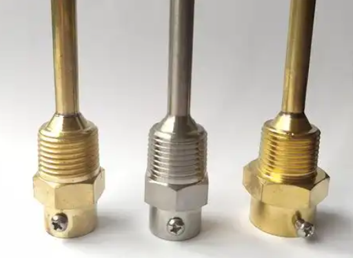
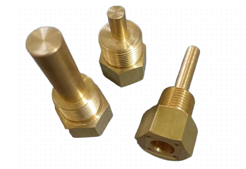
Protection Tubes and Thermowells
Protection tubes and thermowells are tubular housings inserted directly into pipes, vessels, furnaces, or ducts. Typical features include:
- Closed or reduced-diameter tip for improved thermal coupling
- Straight, tapered, or stepped outside profile
- Threaded, flanged, or welded process connection
Thermowells are often designed following standardized dimensions and calculation methods to withstand fluid-induced vibration and pressure loads while maintaining acceptable response characteristics.
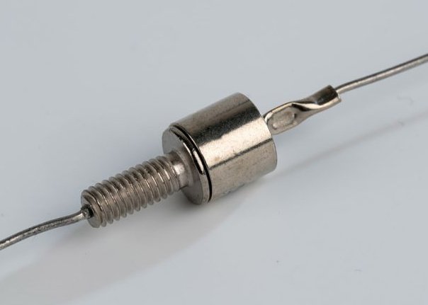
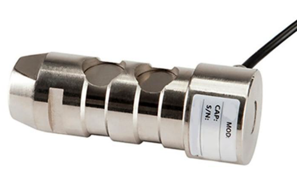
Sheathed Probes and Mineral-Insulated Assemblies
Mineral-insulated (MI) cable assemblies and sheathed probes integrate the sensing element, compacted insulating powder (commonly magnesium oxide), and a metallic sheath. The housing is formed by the outer sheath and any additional fittings or protective sleeves. This design offers:
- High flexibility for routing in confined spaces
- Excellent vibration resistance
- Good high-temperature durability depending on sheath alloy
Ceramic Protection Tubes
For very high temperatures or chemically aggressive environments, ceramic protection tubes are widely used. They provide:
- Service temperatures exceeding typical metallic alloys
- Resistance to many corrosive slags and atmospheres
- Electrical insulation inherent to ceramic materials
Ceramic tubes may be used alone or inside metallic outer tubes for combined mechanical and chemical protection.
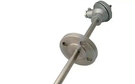
Flanged and Weld-In Housings
In large process lines and pressure vessels, flanged or weld-in housings provide stable, leak-tight interfaces. These housings typically include:
- Process flanges matching local standards
- Reinforcement pads or collars for weld-in nozzles
- Dedicated sealing surfaces and gasket arrangements
Specialty Enclosures and Junction Heads
At the cold end, sensor housings often incorporate junction heads or terminal enclosures that house connection blocks, transmitters, or connectors. Typical junction heads include:
- Die-cast aluminum or stainless steel enclosures
- Bayonet or screw covers with sealing gaskets
- Internal mounting feature for signal conditioning modules
Materials Used in High-Temperature Sensor Housings
The material selection for high-temperature sensor housings is crucial for reliability and service life. The choice depends on temperature range, atmosphere, mechanical requirements, and cost constraints.
| Material Category | Typical Alloys / Grades | Approximate Max Service Temperature (in air) | Key Characteristics |
|---|---|---|---|
| Stainless steels | 304, 310, 316, 321, 347 | 600–1100 °C (grade dependent) | Good general corrosion resistance, widely available, cost-effective; limited in very high temperature or highly reducing atmospheres. |
| Heat-resistant alloys | Inconel 600/601/625, Incoloy 800/825, Hastelloy grades | 900–1150 °C (environment dependent) | Enhanced high-temperature strength and oxidation resistance; suitable for many furnace and petrochemical conditions. |
| Refractory metals | Molybdenum, tungsten, tantalum, niobium (often with protective coatings) | 1200–2000 °C (in inert/vacuum) | Very high melting points and creep strength; sensitive to oxidation, often used in vacuum or inert atmospheres. |
| Ceramics | Alumina, mullite, silicon carbide, silicon nitride | 1200–1700 °C (grade dependent) | High temperature capability and chemical stability; brittle with limited impact resistance; thermal shock limitations vary by type. |
| Nickel-chromium steels | Special furnace tube alloys | 900–1150 °C | Designed for furnace tubes and protection tubes; good resistance to scaling and carburization. |
Metallic Housing Materials
Metallic housings are widely used due to their ductility, weldability, and resistance to mechanical damage. Key parameters for selection include:
- Yield and tensile strength at service temperature
- Creep resistance for prolonged high-temperature exposure
- Oxidation and corrosion behavior in the process atmosphere
- Compatibility with welding or brazing processes used in assembly
Ceramic Housing Materials
Ceramic tubes and components are selected based on:
- Maximum service temperature
- Resistance to target slags, melts, and process gases
- Thermal shock resistance (dependant on thermal expansion and conductivity)
- Mechanical strength and fracture toughness
Composite and Multi-Layer Structures
In some applications, composite designs are used, such as a ceramic inner tube within a metallic outer tube, or metallic housings with protective coatings. These designs aim to combine:
- Outer mechanical strength and impact protection
- Inner chemical and thermal resistance
Sealing Methods and Environmental Protection
Reliable sealing is essential for maintaining sensor performance and preventing leaks of process fluids. Sealing strategies vary depending on temperature level and process medium.
Gasket and O-Ring Sealing
For low to medium temperature regions (typically below 250–300 °C, depending on material), elastomer and polymer-based seals are common in junction heads and cable entries. For higher temperatures, compressed fiber, graphite, or metal gaskets are used at flanged connections.
Welded and Brazed Joints
In high-temperature zones where soft seals are unsuitable, welded or brazed joints provide permanent leak-tight connections. Features include:
- Full penetration welds at process interfaces
- Controlled brazing of ceramic-to-metal transitions
- Post-weld heat treatment or stress-relief where required
Hermetic Feedthroughs and Cable Glands
In harsh environments, sensor leads may pass through hermetic feedthroughs that maintain pressure and environmental isolation. Design options are:
- Ceramic-to-metal compression feedthroughs for high temperature and pressure
- Sealed metal cable glands with appropriate temperature ratings
- Glass-sealed connectors for electrically isolated, gas-tight interfaces
Ingress Protection and Enclosure Ratings
The overall housing system, including junction heads and cable interfaces, may be designed to meet specified ingress protection ratings. This ensures resistance to dust, water jets, immersion, or exposure to wash-down processes. Careful attention is required for:
- Cover sealing surfaces and gasket compression
- Thread engagement and sealing tapes or compounds
- Orientation and placement of cable entries to avoid water accumulation
Performance Parameters and Typical Specifications
Manufacturers of high-temperature sensor housings specify a range of performance parameters. These help users evaluate suitability for particular applications and environments.
| Parameter | Typical Range or Description | Notes |
|---|---|---|
| Continuous operating temperature | 200–1200 °C (standard metallic housings); up to 1600 °C and above for ceramics and refractory metals | Limited by material, atmosphere, and mechanical loading. |
| Pressure rating | Vacuum to several hundred bar, depending on design and wall thickness | Subject to thermowell and pressure equipment design rules. |
| Ingress protection (IP) | Typical IP65, IP67, or IP68 for junction heads and connection boxes | Refers mainly to enclosure portion, not all hot-zone components. |
| Mechanical vibration resistance | Dependent on geometry and mounting; often specified with test levels in m/s² or g | Critical for engine and rotating machinery installations. |
| Response time impact | Compared to bare sensor, housing may add several seconds or more to time constant | Varies with wall thickness and medium (air, gas, liquid). |
| Connection interfaces | Thread types (NPT, BSP), flanges, weld-in sockets, bayonet fittings | Selected according to regional and industry standards. |
Selection Considerations for High-Temperature Sensor Housings
Selecting a suitable housing requires a methodical evaluation of process data, sensor type, and installation constraints.
Process Temperature and Atmosphere
Define the following process conditions as accurately as possible:
- Minimum, normal, and maximum temperatures
- Expected peak excursions and frequency
- Gas or liquid composition, including contaminants
- Presence of condensates, slag, or deposits
This information determines candidate material classes and whether metallic, ceramic, or composite housings are appropriate.
Pressure, Flow, and Mechanical Loading
Key input data include:
- System pressure and pressure fluctuations
- Flow velocity and density of the process medium
- Mechanical support points and cantilever lengths
- Vibration sources and vibration frequency ranges
These parameters influence housing thickness, profile, and connection type. For thermowells, calculations according to industry practices help avoid resonance and fatigue failure.
Measurement Dynamics and Installation Location
Define the required response time and spatial resolution of the measurement. Consider:
- Distance from the housing tip to the actual measurement location
- Influence of mounting depth within pipes or ducts
- Need for fast response for control loops
Maintenance, Replacement, and Accessibility
In many installations, housings are intended to remain in service while sensors are periodically replaced. To support this strategy:
- Choose housings with removable inserts or cartridges
- Ensure accessible junction heads or connectors
- Consider standardization of connection sizes and lengths
Compatibility with Sensor Types and Electronics
Sensor housings must accommodate the physical dimensions and operating conditions of the selected sensor technology, such as:
- Thermocouples (single or multiple junctions)
- RTDs with 2-, 3-, or 4-wire configurations
- Integrated transmitters or amplifiers located in the head
Internal clearances, insulation requirements, and wiring routes must be considered in the housing design.
Typical Pain Points in High-Temperature Sensor Housing Use
Users dealing with high-temperature sensor housings frequently encounter practical difficulties. Understanding these allows better design and specification decisions.
Premature Corrosion or Oxidation Damage
Exposure to unsuitable atmospheres can cause rapid degradation of housing materials. Typical issues include:
- Unexpected sulfidation or carburization in furnace gases
- Scaling and spalling of oxide layers at high temperatures
- Local thinning due to combined corrosion and erosion
These problems often result from incomplete characterization of process media or the use of generalized material choices instead of application-specific alloys or ceramics.
Mechanical Failure from Vibration and Flow-Induced Forces
In flowing media, poorly sized or overlong thermowells can experience severe dynamic loading. Potential consequences are:
- Thermowell vibration at resonance frequencies
- Fatigue cracking near process connections
- Breakage leading to sensor loss and potential process leakage
Appropriate design calculations, along with tapered or shortened geometries, can reduce such risks.
Slow Response and Measurement Lag
Heavily built housings may protect sensors but introduce a significant delay between actual process temperature change and measured value. This can be problematic in control loops that require rapid feedback, leading to:
- Overshoot and undershoot in temperature-controlled processes
- Difficulty tuning control parameters
Balancing wall thickness, material selection, and insertion depth helps achieve acceptable response times while maintaining durability.
Seal Degradation and Loss of Ingress Protection
Seals and gaskets located closer to hot zones than intended may be exposed to temperatures beyond their rating. Over time this can cause:
- Hardening and cracking of elastomer gaskets
- Leak paths for water, dust, or corrosive vapors
- Reduced IP rating and compromised safety
Proper placement of seals in cooler regions and selecting high-temperature sealing materials where necessary are key preventive measures.
Installation and Mounting Guidelines
Correct installation is essential for the performance of high-temperature sensor housings. Improper mounting can negate the advantages of a well-designed housing.
Insertion Length and Immersion Depth
For temperature sensors, the immersion depth should be sufficient to ensure that the sensitive element is fully exposed to the representative process temperature. General recommendations include:
- Immersion length of at least several times the housing diameter
- Consideration of boundary layers in flowing media
- Avoiding contact between housing tip and vessel walls when not intended
Orientation and Support
Support structures may be required for long housings to prevent excessive bending loads. Considerations:
- Use of guide supports or sleeves in very long insertions
- Orientation to minimize accumulation of condensate in cavities
- Avoiding mechanical interference with moving parts in the process
Welding, Threading, and Flange Assembly
For weld-in housings, qualified procedures and trained personnel are important to ensure the intended strength and leak tightness. For threaded and flanged connections:
- Select thread sealing compounds compatible with process and temperature
- Apply appropriate torque according to manufacturer recommendations
- Use specified gasket materials and surface finishes for flanges
Maintenance, Inspection, and Service Life
High-temperature sensor housings are often expected to remain in service for extended periods. However, periodic inspection is necessary to manage aging and wear.
Inspection Intervals and Methods
Inspection intervals depend on operating severity and safety requirements. Typical methods include:
- Visual inspections for scaling, deformation, and discoloration
- Wall thickness measurements using ultrasonic testing (for metal housings)
- Dye penetrant or other non-destructive testing at critical welds
Criteria for Replacement
Replacement may be necessary when any of the following are detected:
- Wall thinning beyond allowable limits
- Cracks, deep grooves, or severe deformation
- Evidence of persistent leakage or compromised sealing surfaces
Handling and Storage
Before installation, housings should be stored in clean, dry environments. Ceramics require protection from impact and sudden temperature changes. Metallic housings should be handled to avoid denting or surface damage at sealing and mating surfaces.
Integration with Sensors and Measurement Systems
High-temperature housings are part of a broader measurement chain that includes sensing elements, wiring, conditioning electronics, and control systems. Proper integration ensures consistent operation.
Sensor Positioning and Fixation Inside Housings
To maintain repeatable measurement performance:
- Sensor tips should be firmly seated at the housing tip where designed
- Compression fittings or spring-loaded inserts can maintain contact under thermal expansion
- Internal insulation materials must withstand local temperatures
Cable Routing and Protection
Cables exiting the housing should be routed away from hot surfaces and sources of mechanical damage. Protective conduits, flexible metallic hoses, and high-temperature cable jackets are often used to maintain signal integrity and safety.
Use of Head-Mounted Transmitters
Many high-temperature sensor assemblies incorporate head-mounted transmitters within the junction head. These devices convert sensor signals into standardized outputs. When used:
- Ensure ambient temperature at the head remains within transmitter limits
- Provide suitable sealing for the enclosure
- Allow space for transmitter mounting and wiring within the head
FAQ: High-Temperature Sensor Housings
What temperature range can typical high-temperature sensor housings handle?
The usable temperature range depends strongly on the housing material and construction. Standard stainless steel housings are commonly used up to approximately 600–800 °C, while specialized heat-resistant alloys can operate around 900–1100 °C in appropriate atmospheres. Ceramic protection tubes may be applied at temperatures from roughly 1200 °C up to 1600 °C or higher, depending on the ceramic type and process environment. Always refer to manufacturer data for continuous and peak temperature ratings under the specific conditions of use.
How do I choose between a metallic and a ceramic sensor housing?
Choose metallic housings when mechanical robustness, weldability, and vibration resistance are priorities, and when the temperature and atmosphere are within the capabilities of available alloys. Metallic housings are suitable for many power generation, chemical, and engine applications. Ceramic housings are more appropriate when process temperatures exceed the safe limits of metals or when the atmosphere is highly corrosive to metallic alloys, such as in some molten metal and high-temperature furnace environments. However, ceramics are more brittle and sensitive to impact, so installation and handling must account for these characteristics.
Do high-temperature housings affect sensor response time?
Yes. Any housing placed between the sensor element and the process medium adds thermal mass and may slow down heat transfer. Thick-walled or heavy protection tubes can significantly increase the response time compared to bare sensors. To limit this effect, designers use tapered or reduced tips, thinner walls in non-critical areas, and high-conductivity materials where feasible. During specification, it is important to consider the required response time of the measurement and ensure that the housing design is compatible with the control dynamics of the process.
Can I replace sensors without removing the housing from the process?
In many designs, yes. High-temperature housings are often installed permanently, while the sensor element is mounted on a removable insert or cartridge. This allows the sensor to be withdrawn and replaced through the junction head without disturbing the housing or process connection. To use this approach, the housing must be designed for adequate clearance and guidance of the insert, and appropriate safety procedures must be followed regarding process isolation and temperature conditions during maintenance.
