

CNC turning is widely used to produce rotational parts with tight dimensional requirements. Understanding what tolerance levels are realistically achievable, how they are specified, and what affects them is essential for engineers, machinists, and purchasers who need reliable and repeatable turned components.
What Tolerance Means in CNC Turning
In CNC turning, tolerance is the permissible variation in a dimension from its nominal value. It defines the acceptable upper and lower limits within which the actual size of the turned feature must lie. Tolerance specifications guide both part design and process planning, ensuring interchangeability, proper fit, and functional performance.
Key aspects of tolerance in CNC turning include:
- Size tolerance: deviation allowed for diameters, lengths, grooves, shoulders, and threads.
- Form tolerance: straightness, roundness, cylindricity, and flatness of turned surfaces.
- Orientation and position: angularity, perpendicularity, concentricity, and runout relative to datums.
In practice, tolerance is not only a geometric concept; it also directly impacts cycle time, tooling, inspection strategy, and total part cost. Tighter tolerance typically demands more stable processes, more precise equipment, and more rigorous quality control.

Typical Tolerance Ranges in CNC Turning
The achievable tolerance in CNC turning depends on the machine tool, tooling, workholding, material, and process setup. However, there are common reference ranges used in industry for guidance when no extreme conditions apply.
For general production on modern CNC lathes, a typical capability for diameters is often in the range of ±0.01 mm to ±0.05 mm (±0.0004 in to ±0.002 in), with finer tolerances possible under controlled conditions.
Typical indicative ranges are:
- Standard commercial turning: about ±0.05 mm to ±0.10 mm (±0.002 in to ±0.004 in).
- Precision turning: about ±0.005 mm to ±0.02 mm (±0.0002 in to ±0.0008 in).
- High-precision turning on specialized equipment: down to ±0.001 mm to ±0.003 mm (±0.00004 in to ±0.00012 in) for selected features.
Not every dimension on a part can practically be held to the minimum possible tolerance. Critical features may be held very tight, while non-critical ones are left with more generous tolerances to control cost and maintain productivity.
Reference to ISO Tolerance Grades (IT Grades)
International standards, such as ISO 286, classify tolerances into IT (International Tolerance) grades. These grades offer a systematic way to define achievable tolerance bands for different manufacturing processes and nominal sizes. CNC turning can cover a wide range of IT grades depending on the process capability.
| IT Grade | General description | Common application in turning |
|---|---|---|
| IT7–IT8 | Medium precision | Standard shaft and hole fits for many industrial components |
| IT6 | Precision | Locating diameters, bearing seats, tight sliding or interference fits |
| IT5 | High precision | High-precision shafts, spindles, and critical sealing surfaces |
In practice, many CNC-turned parts fall within IT7 to IT9 for general features and IT5 to IT6 for critical diameters. When specifying tolerances, it is useful to correlate dimensional limits to an IT grade to ensure consistency with widely recognized standards.
Shaft and Hole Fits in Turned Components
Many turned parts are designed to fit with mating components such as bearings, bushings, gears, and housings. In these cases, tolerance is expressed not only as an independent limit but also as a fit system between a shaft and a hole. ISO fit systems like H7/g6 or H7/h6 are commonly used as references in drawings and production documents.
Key fit categories include:
- Clearance fits: ensure a positive clearance under all tolerance conditions for free movement.
- Transition fits: may result in small clearance or slight interference, used where alignment and location are important.
- Interference fits: always produce a negative clearance (press or shrink fits) for rigid connections.
| ISO fit example | Fit type | Typical usage |
|---|---|---|
| H7/g6 | Sliding clearance fit | Shafts that must slide but have limited play |
| H7/h6 | Close clearance fit | Locating shafts, light press of bearings depending on size |
| H7/p6 | Interference fit | Press-fit joints for gears or coupling hubs |
For turned shafts, the shaft tolerance zone (such as g6, h6, k6, m6) is produced by selecting the target diameter and finishing passes. For holes, tolerance is often applied to subsequent operations, such as boring or reaming, but can also be obtained on turning centers equipped with suitable tools and boring bars.
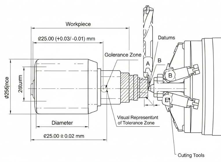
Dimensional Tolerances vs Geometric Tolerances
Dimensional tolerance defines the acceptable variation in size (e.g., diameter 20 ±0.01 mm). Geometric tolerances (GD&T) control the shape, orientation, and location of features relative to datums, which is particularly important in rotating components.
Common geometric tolerances in CNC turning include:
- Roundness (circularity): ensures cross-sections are close to true circles.
- Cylindricity: controls roundness and straightness along the full length of a cylinder.
- Runout and total runout: control the variation of a surface relative to an axis during rotation.
- Concentricity: limits the center variation of a feature relative to a datum axis.
- Straightness: applies to axial lines or generatrix of cylindrical surfaces.
In many rotating assemblies, geometric tolerances may be more critical to function than a single size tolerance. For example, a shaft may be within the specified diameter, but excessive runout can still cause vibration or uneven wear. Effective coordinate between size tolerances and geometric controls increases functional reliability.
How Precise Can CNC Turning Get in Practice?
Under standard production conditions, CNC turning can consistently hold dimensional tolerances in the ±0.01 mm range for diameters and slightly larger values for lengths, depending on setup. With high-quality machines, stable environment, and optimized process parameters, even tighter tolerances are realistic for specific features.
Key aspects of practical precision include:
1) Small diameter features
Small-diameter parts, such as pins, miniature shafts, and valve components, can achieve tolerances in the range of ±0.002 mm to ±0.005 mm on high-precision turning centers. However, stiffness of workpiece and tool, as well as chip control, becomes increasingly important at such scales.
2) Medium to large diameter features
For typical industrial shafts and flanges, CNC lathes can hold tolerances around ±0.005 mm to ±0.02 mm on diameters when adequately supported with chucks, collets, or steady rests. Long slender parts may require special support and machining strategies to avoid deflection.
3) Lengths, shoulders, and grooves
Axial dimensions like lengths and shoulder positions usually have slightly looser tolerance than diameters. Typical ranges are ±0.02 mm to ±0.10 mm, although special precision setups can reduce that. Axial features are influenced by backlash compensation, turret indexing repeatability, and thermal drift along the machine bed.
Factors That Influence Tolerance in CNC Turning
The final tolerance achievable on a turned part is the result of multiple interacting factors. Understanding these helps set realistic tolerances and choose the right process conditions.
1. Machine tool capability
CNC lathe design and condition heavily influence accuracy:
- Linear and rotary axis positioning accuracy and repeatability.
- Spindle runout and thermal stability.
- Guideway and ball screw condition (wear, backlash, lubrication).
- Type of machine: standard CNC lathe, precision turning center, or high-precision hard-turning machine.
Higher grade machines have tighter positioning tolerances, better compensation systems, and more stable structures, improving the achievable part tolerance.
2. Workholding and part rigidity
Clamping method determines how the workpiece behaves under cutting forces:
- Three-jaw chucks: versatile but may introduce radial runout if not precisely adjusted.
- Collet chucks: offer better concentricity and are preferred for small to medium diameters with close tolerances.
- Soft jaws: can be machined to match a particular part, improving location accuracy and support.
- Steady rests and tailstocks: help support long or slender parts, reducing bending and vibration.
Insufficient rigidity can cause deflection, chatter, and dimensional drift along the turned surface, making it difficult to maintain tight tolerances, especially over long spans.
3. Cutting tools and tool wear
Tool geometry, material, and condition directly affect the machined size:
- Insert nose radius and wear have a clear influence on surface finish and dimensional accuracy.
- Tool overhang and clamping rigidity affect deflection and vibration.
- Tool wear leads to gradual dimension changes, requiring tool offset compensation or tool life monitoring.
Using appropriate tool grades, coatings, and shapes for the material, plus a robust tool management strategy, supports consistent tolerance control over long production runs.
4. Material properties
Different materials react to cutting forces and heat in distinct ways:
- Soft materials (aluminum, brass) are easier to machine but may show built-up edge or burrs if parameters are not optimized.
- Hard steels or superalloys require more rigid setups and appropriate tooling, as cutting forces are higher.
- Materials with residual stress can deform during machining, causing unexpected dimensional shifts.
The choice of bar stock or preform quality, including straightness, hardness, and microstructure uniformity, also influences final dimensions.
5. Thermal effects
Temperature changes impact the CNC machine, tools, and workpiece:
- Spindle and axis heating cause expansion, resulting in slow drift of dimensions during production.
- Workpiece temperature increases during cutting, leading to expansion and possible dimensional change as it cools.
- Ambient temperature variations in the workshop can affect the entire system.
Modern machines often include thermal compensation and temperature monitoring, but controlled environment and stable coolant conditions remain important when working with very tight tolerances.
6. Process parameters (feeds, speeds, depth of cut)
Cutting conditions influence both forces and heat generation:
- High cutting forces at large depths of cut can cause deflection and reduce accuracy.
- Very low feeds may improve surface finish but increase rubbing and heat build-up, which can distort dimensions.
- Finishing passes with small depth of cut and optimized feed/speed are used to achieve final tight tolerance.
Balancing productivity and stability is crucial. Stable chip formation and controlled cutting forces support consistent, repeatable dimensions.
Surface Finish and Its Relationship to Tolerance
Surface roughness values (Ra, Rz) do not represent tolerance directly, but they are closely related. A rough surface has peaks and valleys that can influence effective contact and fit with mating components, especially in high-precision assemblies.
Common surface finishes in CNC turning are:
- General turned finish: about Ra 1.6–3.2 μm.
- Fine finishing: about Ra 0.4–1.6 μm.
- High-precision finishing or hard turning: as low as Ra 0.1–0.4 μm in favorable conditions.
Finer surface finish often coincides with tighter tolerance because both usually require light finishing passes, stable setup, sharp tools, and consistent cutting conditions. However, specifying an extremely low roughness without functional need may increase cost without clear benefit.
Pain Points and Common Issues in Holding Tight Tolerances
When tolerances become very tight, several practical difficulties may arise:
1) Dimensional drift during production
Over long runs, tool wear, thermal expansion, and material variability can cause gradual deviation in dimensions. If not monitored, parts may move out of tolerance before the issue is detected. This leads to rework, scrap, or additional inspection steps.
2) Difficulty with long slender parts
Long shafts and thin-walled cylinders are prone to bending and vibration during turning. Even with a precise machine, deflection can cause taper or barrel shapes along the length, making it challenging to maintain uniform diameter tolerance. Additional supports and optimized cutting strategies are often necessary.
3) Overly tight, non-functional tolerances
Sometimes drawings specify very tight tolerances without a clear functional requirement. This increases machining time, requires more frequent tool changes and additional inspection, and may limit the number of suppliers capable of producing the part economically. Aligning tolerance levels with actual functional needs reduces unnecessary complexity.
Best Practices for Specifying Tolerances for Turned Parts
Effective tolerance specification helps achieve functional requirements without excessive cost. Recommended practices include:
1) Define functional requirements clearly
Identify which features are critical for fit, sealing, alignment, or performance. Use tight tolerances only on these features. For non-critical dimensions, more generous limits are usually sufficient and easier to maintain in production.
2) Use standard tolerance and fit systems
Where possible, use standardized IT grades and ISO shaft/hole fits. This makes it easier for suppliers to understand expectations and select appropriate processes. Using standard tolerance classes also simplifies interchangeability between parts from different production batches.
3) Combine dimensional and geometric tolerances appropriately
Use geometric tolerances (such as runout or cylindricity) in addition to size limits when functional performance depends on shape or alignment. For example, specifying a diameter plus a runout requirement can more clearly define the functional needs of a rotating surface than diameter alone.
4) Coordinate tolerance with material and heat treatment
If a part is heat-treated after turning, dimensional changes may occur. In such cases, either allow sufficient tolerance to accommodate these changes or plan finishing operations (grinding or hard turning) after heat treatment. For stable tolerance, consider material stability, residual stresses, and any post-machining processes (plating, coating, polishing).
5) Communicate inspection requirements
Indicate on drawings which dimensions are critical to inspect 100% and which can be sampled. For very tight tolerances, specify the measurement reference (e.g., diameter measured at a given distance from a shoulder) and inspection aids if necessary. Clear communication reduces ambiguity and helps ensure that both designer and manufacturer interpret tolerance requirements in the same way.
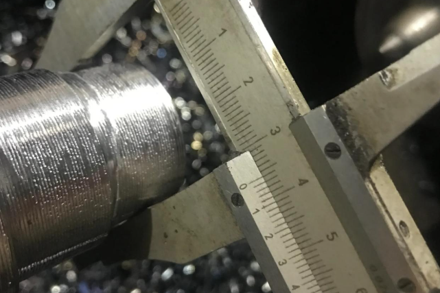
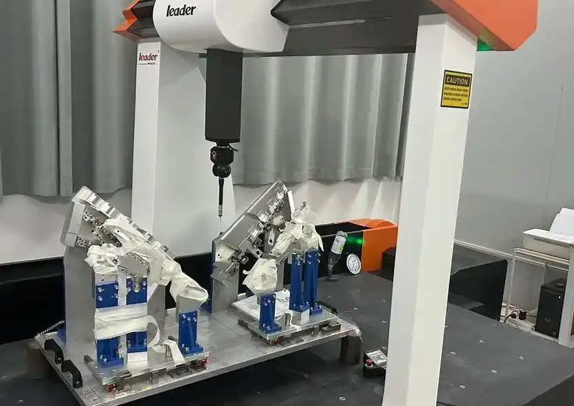
Measurement and Inspection of Turned Tolerances
Verification of tight tolerances requires appropriate measurement equipment and methods. Measurement accuracy must always be significantly better than the tolerance being measured to provide meaningful results.
1) Basic measurement tools
Common tools in turning workshops include:
- Micrometers (outside, inside, depth) for high-accuracy size measurement.
- Calipers for quick checks, usually on dimensions with relatively generous tolerance.
- Dial indicators and test indicators to check runout, concentricity, and axial displacement.
Micrometers with resolution down to 0.001 mm (0.00005 in) are standard for precision turned parts.
2) Advanced measurement equipment
For tighter tolerances and geometric controls, additional equipment is used:
- CMM (Coordinate Measuring Machine) for comprehensive dimensional and geometric inspection.
- Roundness and cylindricity measuring machines for rotating parts with high precision requirements.
- Surface roughness testers to verify Ra, Rz, and related parameters.
High-precision applications often require climate-controlled inspection rooms to minimize environmental influence on measurements.
3) In-process and post-process inspection
To maintain consistent tolerance during production:
- In-process checks: operators measure critical dimensions at defined intervals and adjust tool offsets as necessary.
- First article inspection: a full dimensional check for the initial part of a batch verifies that the setup is correct.
- Statistical process control (SPC): monitoring of key characteristics over time helps keep the process within capability limits.
Appropriate inspection strategies reduce scrap, support early detection of deviation, and provide traceability for quality assurance.
Cost Implications of Tight Tolerances in CNC Turning
Tolerance level has a direct impact on the cost and lead time of CNC-turned parts. While CNC technology enables high precision, pushing tolerances unnecessarily close can significantly increase total cost. Consider the following cost-related factors:
- Setup and programming: tight tolerances may require additional setups, more careful alignment, and extra test runs.
- Cutting time: finishing passes at reduced feed and depth increase cycle time per part.
- Tooling: frequent tool changes and specialized inserts or boring bars may be required.
- Inspection: more complex and frequent measurements, sometimes with advanced equipment, add to the cost.
- Scrap and rework: tighter tolerances reduce the margin for variation, increasing the risk of nonconformity.
Balancing tolerance with actual functional requirements and considering process capability is essential for cost-effective production. Discussing tolerance levels with manufacturing partners early in the design phase often leads to optimized, realistic specifications.
Practical Guidelines for Designers and Engineers
To make effective use of CNC turning capabilities and achieve reliable tolerance control, designers and engineers can follow these guidelines:
- Assign tight tolerance only to critical features and keep others at standard levels.
- Use clear and standardized tolerance notation, including ISO fits, IT grades, and GD&T symbols.
- Consider machining sequence and accessibility when specifying tolerances on internal diameters, undercuts, and complex profiles.
- Take into account future service operations such as assembly, disassembly, and possible wear; specify tolerances that maintain functionality over the part lifecycle.
- When in doubt, consult with manufacturing experts to confirm that desired tolerances are realistic on available equipment and materials.
Properly defined tolerance frameworks help prevent misunderstandings, reduce trial-and-error in production, and shorten the time from design to stable serial manufacturing.
