
CNC milling technology is central to modern manufacturing, product development, and precision engineering. Among the available configurations, 3-axis and 5-axis CNC milling machines are the most widely used. Understanding their differences in movement, capability, accuracy, cost, and application range is critical for engineers, designers, and manufacturing planners who need to select appropriate equipment or external machining services.
Fundamental Definitions and Motion Principles
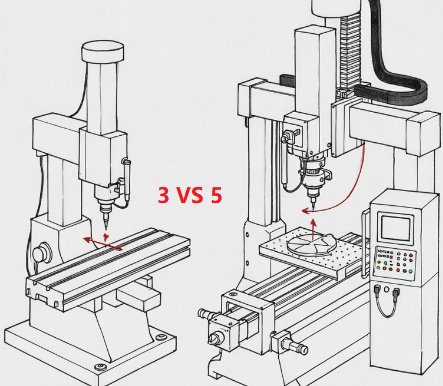
3-axis and 5-axis CNC milling machines are differentiated mainly by the number of directions in which the cutting tool or workpiece can move or be oriented during machining.
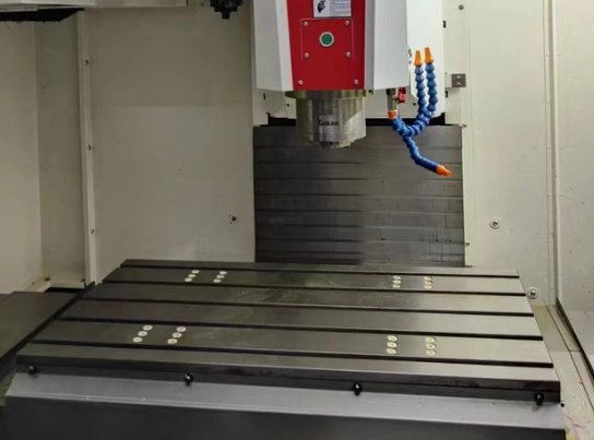
3-Axis CNC Milling Basics
A 3-axis CNC mill uses three linear axes:
- X-axis: left–right movement
- Y-axis: front–back movement
- Z-axis: up–down movement
The cutting tool (or spindle) typically moves along these three linear axes while the workpiece remains fixed on the table during a single setup. All tool orientations are perpendicular to the machine table, so cutting is performed mainly from the top (and sometimes from the sides with appropriate fixturing and toolpaths, but without changing tool tilt angles).
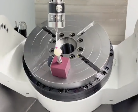
5-Axis CNC Milling Basics
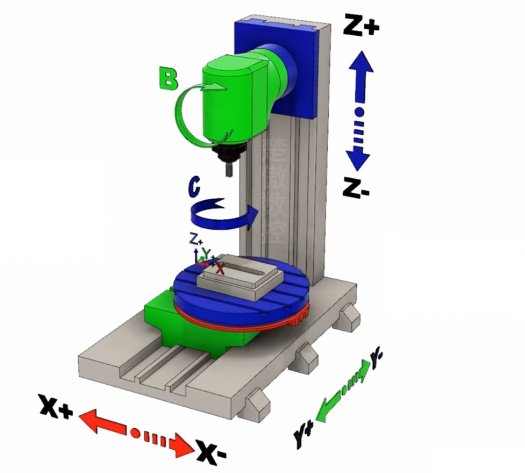
A 5-axis CNC milling machine controls five degrees of freedom during machining. In addition to the X, Y, and Z linear axes, it has two rotational axes, usually referred to as A, B, or C. Common configurations include:
- Table-table: the table rotates (A-axis) and tilts (C-axis)
- Head-head: the spindle head tilts and rotates
- Head-table: one rotational axis in the head, one in the table
These extra axes allow the cutting tool to approach the workpiece from multiple angles without manual repositioning, enabling machining of complex surfaces and undercuts in a single setup.
Key Technical Differences Between 3-Axis and 5-Axis
The following table summarizes the main distinctions between 3-axis and 5-axis CNC milling systems in terms of motion, complexity, and typical use cases.
| Aspect | 3-Axis CNC Milling | 5-Axis CNC Milling |
|---|---|---|
| Controlled axes | X, Y, Z (linear) | X, Y, Z + 2 rotational axes (A/B/C) |
| Tool orientation during cut | Fixed, usually vertical | Continuously variable, multi-angle |
| Geometric complexity | Suited for prismatic parts, simple contours | Suited for complex 3D surfaces and undercuts |
| Setups per part | Often multiple setups and re-clamping | Frequently one setup, sometimes two |
| Programming difficulty | Lower, standard CAM and toolpaths | Higher, requires advanced CAM strategies |
| Machine and tooling cost | Lower initial investment | Higher machine, tooling, and maintenance cost |
| Typical industries | General machining, fixtures, basic components | Aerospace, medical, automotive performance parts, molds |
| Surface quality potential | Good, but limited on complex geometry | Very high on complex curved surfaces |
| Fixturing requirements | More jigs, manual repositioning | More sophisticated but fewer re-clamps |
Capabilities of 3-Axis CNC Milling
3-axis milling is widely used due to its versatility, relative simplicity, and cost-efficiency. It is appropriate for a broad range of parts that do not require complex 3D surface machining or deep multi-angle features.
Typical Part Geometries
3-axis milling is suitable for parts with:
- Flat surfaces, pockets, slots, and holes
- Simple 2.5D features (step heights, simple contours)
- Chamfers and fillets accessible from one main direction
- Basic 3D contours that do not need tool tilting
By rotating or flipping the workpiece between operations, 3-axis machines can handle multiple sides of a part. However, each new orientation typically requires a separate setup and re-alignment.
Accuracy and Tolerances
Well-maintained industrial 3-axis CNC mills commonly achieve:
Typical tolerance range:
- General machining: ±0.05 mm to ±0.01 mm
- Precision machining: down to ±0.005 mm, depending on machine quality, thermal stability, tooling, and operator practices
Positional accuracy and repeatability can be high, especially on rigid machines with high-quality linear guides and ball screws. However, when a part requires multiple setups, the combined effect of re-clamping and re-aligning can introduce additional error between faces or features.
Material Compatibility
3-axis mills can process a wide spectrum of materials, including:
- Metals: aluminum, steel, stainless steel, copper alloys, titanium (with appropriate cutting parameters)
- Plastics: ABS, POM (acetal), nylon, PEEK, PC, and others
- Composites: certain fiber-reinforced polymers with suitable tooling and dust extraction
Material removal rates and achievable surface quality depend on spindle power, machine rigidity, cutting parameters, coolant application, and tooling geometry.
Limitations of 3-Axis Milling
Important limitations that influence part design and process planning include:
Accessibility: Features that are hidden behind other surfaces or oriented at steep angles cannot be reached without re-orienting the part. Internally recessed features with limited tool access may be impossible or forced to use long, deflection-prone tools.
Multiple setups: For parts requiring machining on five or more faces or complex angles, 3-axis milling needs repeated re-clamping. Each setup takes time and introduces potential misalignment, affecting geometric relationships and true position of features.
Limited multi-axis contouring: Without tool tilting, maintaining ideal cutting angles on curved surfaces is difficult. This can increase machining time and may limit achievable surface finish on complex 3D geometry.
Capabilities of 5-Axis CNC Milling
5-axis milling extends the ability of 3-axis machines by adding two rotational axes, enabling multi-angle tool orientation. This allows complex shapes to be machined with high accuracy and fewer setups.
Simultaneous vs Indexed 5-Axis
5-axis milling can operate in two main modes:
Indexed (3+2) machining: The additional axes are used to orient the workpiece or tool to a specific angle, then locked while machining occurs with 3-axis interpolation. This approach simplifies programming while still reducing setups and improving access.
Full simultaneous 5-axis machining: All five axes can move concurrently. This enables highly complex toolpaths, such as continuous machining of sculpted surfaces, turbine blades, impellers, and freeform geometry, maintaining optimal tool angles throughout the cut.
Advanced Geometries and Features
5-axis milling supports geometries that are challenging or impossible on 3-axis machines, such as:
- Deep cavities with angled walls and smooth transitions
- Undercuts and back-side features reachable only from tilted directions
- Freeform surfaces with continuous curvature, such as aerofoils
- Complex molds and dies with variable draft angles
- Components with multiple features aligned on non-orthogonal axes
With tool tilting, the cutting edge can be oriented to maintain constant engagement, reduce tool deflection, and improve surface quality.
Surface Finish and Tool Life
5-axis control can significantly influence machining quality:
Surface finish: On complex curved parts, full 5-axis machining can keep the tool at an optimal angle and maintain consistent step-over and scallop height. This often reduces secondary finishing steps like polishing or EDM in mold making.
Tool life: By tilting the tool, the cutting load can be distributed more evenly along the flute length. It also helps avoid cutting with the tool tip alone, which is prone to rapid wear, especially in hard materials.
Shorter tools: The ability to tilt the tool improves access to deep features using shorter, more rigid tools. Shorter tools reduce deflection, vibration, and risk of chatter, which further improves tool life and surface integrity.
Fixturing and Setup Efficiency
5-axis machines can often complete all necessary operations in a single clamp. This reduces:
- Setup time per part
- Number of fixtures required
- Cumulative positioning errors from multiple re-clamps
With a rotary or trunnion table, the part can be rotated to different orientations during the program. This also allows machining on multiple faces without manual intervention.
Dimensional Accuracy and Tolerances
Both 3-axis and 5-axis CNC machines can achieve high precision, but their behavior differs in practice due to machine kinematics, setup strategy, and part complexity.
Factors Influencing Accuracy
Key technical factors that govern accuracy include:
- Machine structural rigidity and thermal stability
- Axis measurement systems (linear scales vs encoders)
- Backlash and compensation in ball screws or drives
- Calibration and volumetric error compensation
- Tool holder quality and spindle runout
- Fixturing rigidity and repeatability
- Cutting parameters and tool deflection
For high-precision applications, machines may use direct linear scales, advanced thermal compensation, and high-resolution rotary encoders for the additional axes.
Comparative Tolerance Capabilities
On parts suitable for 3-axis machining, both 3-axis and 5-axis machines can reach similar local feature tolerances. The benefit of 5-axis often shows on geometrically complex parts, where fewer setups preserve relationships between features. Typical capabilities in industrial practice are:
| Parameter | 3-Axis CNC Milling | 5-Axis CNC Milling |
|---|---|---|
| Feature size tolerance (general) | ±0.05 mm to ±0.01 mm | ±0.05 mm to ±0.01 mm |
| Feature size tolerance (precision) | Down to ±0.005 mm on suitable machines | Down to ±0.005 mm on suitable machines |
| Positional relationship between faces needing multiple setups | More sensitive to re-clamping errors | Often better due to single-setup processing |
| Angular feature alignment | Dependent on fixture design and manual orientation | Controlled by NC-programmed rotary axes |
| Complex freeform surface continuity | Limited control, more segment transitions | Improved control with continuous 5-axis paths |
Actual achievable tolerances depend heavily on machine brand, age, maintenance condition, and the production environment (temperature, vibration, and process stability).
Process Planning Considerations
Selecting between 3-axis and 5-axis milling is not only a machine choice; it is a process-engineering decision driven by part geometry, batch size, cost constraints, and available programming resources.
Programming Complexity and CAM Requirements
3-axis machining uses:
- Standard toolpaths such as contouring, pocketing, drilling, and 3D surfacing
- Simpler tool orientation assumptions, all perpendicular to the workpiece plane
5-axis machining, especially full simultaneous, requires:
- CAM software that can generate multi-axis toolpaths
- Accurate definition of machine kinematics in the post-processor
- Collision checking between tool, holder, spindle, and part/fixture
- Fine-tuning of tool-axis smoothing and orientation control
Programming resources and expertise must be available to use 5-axis machines effectively. Inefficient 5-axis toolpaths can lead to longer cycle times or incomplete utilization of machine capabilities.
Setup and Fixturing Strategy
3-axis setups typically rely on several dedicated fixtures, vices, or modular clamping systems. The process may include:
- Multiple setups to reach all faces
- Manual indexing of the part between operations
- Frequent probing or manual measurement to re-establish datums
5-axis machines often use:
- Compact, multi-face fixtures or zero-point clamping systems
- Rotary tables or trunnion systems that provide automatic repositioning
- Probing routines for automatic work offset setting
This can reduce handling time and errors, particularly for parts with multiple faces and orientations.
Batch Size and Production Volume
For low-volume or prototype runs of geometrically simple parts, 3-axis machines may be more economical. Fixture design can be modest, and programming effort is relatively low.
For recurring production of complex parts, 5-axis machining, despite higher initial cost, can be efficient due to:
- Shorter setup times per batch
- Reduced number of fixtures to manufacture and maintain
- More consistent quality across multiple features and faces
Cost and Economic Considerations
Cost evaluation between 3-axis and 5-axis milling includes equipment investment, programming time, cycle time, tooling, fixturing, and quality requirements.
Machine Investment and Operating Costs
3-axis milling machines usually have:
- Lower capital cost
- Less complex maintenance and servicing
- Simpler control systems, often with lower licensing costs
5-axis machines typically involve:
- Higher purchase price, reflecting more axes, encoders, and mechanical complexity
- Increased maintenance requirements due to additional rotary components
- Potentially higher operator training and CAM software costs
When evaluating equipment, the decision often considers not only the purchase price but the expected utilization rate and the complexity of the parts to be produced.
Cycle Time and Per-Part Cost
On simple parts that do not require complex geometry, 3-axis machining can be more economical, especially if multiple machines are available and programming time is minimal.
On complex parts, the ability of 5-axis machines to:
- Reduce or eliminate manual repositioning
- Maintain optimal cutting conditions
- Machine multiple faces in one setup
often leads to shorter overall lead time and more consistent quality. Cycle-time reduction must be compared against the higher hourly operating cost of a 5-axis machine to assess net per-part cost.
Quality, Rework, and Scrap Rates
For complex components, one of the main economic advantages of 5-axis machining is often improved dimensional consistency and lower rework or scrap rates. Fewer setups translate directly into fewer opportunities for misalignment, which helps preserve geometric relationships between critical features.
Application Domains and Suitable Use Cases
Both 3-axis and 5-axis milling are widely used across industries. The choice is determined by part geometry, tolerance requirements, and production strategy.
Typical 3-Axis CNC Milling Applications
3-axis milling is frequently selected for:
- Flat plates, base plates, and brackets with through-holes and pockets
- Simple housings with accessible internal cavities
- Fixtures and jigs with prismatic geometry
- Standard mechanical components like flanges, blocks, and mounting frames
Industries using 3-axis milling include general mechanical engineering, equipment manufacturing, electronics enclosures, and many other domains where parts are primarily prismatic and requirements do not justify 5-axis investment.
Typical 5-Axis CNC Milling Applications
5-axis milling is often used in:
- Aerospace: turbine blades, blisks, structural components with contoured surfaces
- Medical devices: orthopedic implants, surgical tools with complex geometries
- Automotive and motorsport: cylinder heads, intake and exhaust manifolds, performance components
- Mold and die making: injection molds, compression molds, die-casting tools, trimming dies
- Energy: impellers, pump components, compressor wheels
These parts typically involve freeform surfaces, multi-angle features, and strict tolerances across multiple planes.
Design Considerations for 3-Axis vs 5-Axis Machining
Design for manufacturability depends on the targeted machining approach. Considering machining capabilities at the design stage can decrease costs and improve reliability.
Designing for 3-Axis Milling
When designing for 3-axis machining, it is helpful to:
- Align most critical features to a small number of primary orientations
- Avoid deep, narrow cavities that require long tools
- Use uniform wall thickness where possible
- Limit undercuts and re-entrant geometries
- Provide adequate tool access and clearance around features
Where multiple orientations are unavoidable, it is beneficial to organize features so that they can be combined into as few setups as possible.
Designing for 5-Axis Milling
When 5-axis milling is available, the designer can use more complex geometries but must also consider machine behavior:
- Ensure that tilt angles and rotary ranges needed to access all features are within machine limits
- Provide sufficient clearance around the part for tool and holder movement during rotation
- Avoid excessively tight corners in deep cavities that would require extremely small or long tools
- Consider how the part will be clamped while allowing necessary rotations
It can be advantageous to consult with the machining provider about their specific 5-axis machine configuration (table-table, head-table, or head-head) to confirm feasibility and optimize geometry.
Issues in Selecting 3-Axis or 5-Axis
Choosing between 3-axis and 5-axis milling often involves addressing specific difficulties.
Common Issues When Relying Only on 3-Axis
Some typical complications include:
- Multiple manual setups leading to inconsistent positional accuracy between faces
- Long, slender tools required to reach deep features, increasing deflection and surface roughness
- Inability to machine certain undercuts or angled features, forcing design changes
- Extended lead times due to fixture changes and setup preparation on every orientation
Common Issues When Implementing 5-Axis
While 5-axis machines solve many access problems, there are also constraints:
- Higher requirement for skilled CAM programmers familiar with multi-axis paths
- Need for robust collision detection and verification to avoid tool or holder impacts
- More complex machine kinematics, which must be accurately modeled in the post-processor
- Higher initial capital cost that demands sufficient utilization to justify the investment
How to Decide Between 3-Axis and 5-Axis CNC Milling
A systematic evaluation can guide selection for a given part or project. Consider:
1) Geometry and Feature Accessibility
Assess whether all features are reachable from a small number of principal directions without undercuts. If the part has deep, angled, or overhanging features that would require complex fixturing or multi-step machining on a 3-axis machine, 5-axis machining may be more suitable.
2) Tolerance and Surface Requirements
If the design contains critical relationships between features on multiple faces or complex freeform surfaces requiring smooth continuity and high surface quality, 5-axis machining can reduce geometric errors and minimize finishing operations.
3) Volume and Lifecycle
For a limited number of parts with relatively simple geometry, 3-axis machining generally suffices. For long-term production of complex components, reduced setups, lower scrap, and improved repeatability may offset the higher cost of 5-axis machining.
4) Available Resources and Skills
Evaluate available machining resources, CAM systems, and programming expertise. If 5-axis capability is not supported by suitable software or trained personnel, the theoretical advantages may not translate into actual process improvements.
Conclusion
3-axis and 5-axis CNC milling each have clear technical roles in manufacturing. 3-axis machining is robust, widely available, and efficient for prismatic parts and many general-purpose components. 5-axis machining extends capabilities to complex geometries, multi-angle features, and high surface quality across multiple faces, often within a single setup.
Selection between 3-axis and 5-axis should be based on part geometry, tolerance requirements, batch size, and process resources. Understanding the strengths and technical characteristics of each approach helps engineers and manufacturing planners choose the most appropriate and economical method for each application.
